Page 506 of 1449

ENGINE OVERHAUL -Oil Pump and Oil Pan11B-52
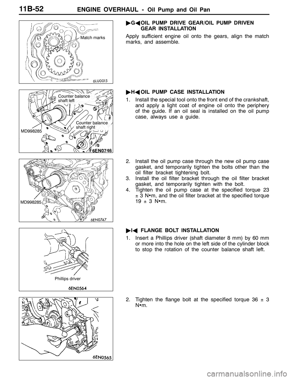
"GAOIL PUMP DRIVE GEAR/OIL PUMP DRIVEN
GEAR INSTALLATION
Apply sufficient engine oil onto the gears, align the match
marks, and assemble.
"HAOIL PUMP CASE INSTALLATION
1. Install the special tool onto the front end of the crankshaft,
and apply a light coat of engine oil onto the periphery
of the guide. If an oil seal is installed on the oil pump
case, always use a guide.
2. Install the oil pump case through the new oil pump case
gasket, and temporarily tighten the bolts other than the
oil filter bracket tightening bolt.
3. Install the oil filter bracket through the oil filter bracket
gasket, and temporarily tighten with the bolt.
4. Tighten the oil pump case at the specified torque 23
±3N•m, and the oil filter bracket at the specified torque
19±3N•m.
"IAFLANGE BOLT INSTALLATION
1. Insert a Phillips driver (shaft diameter 8 mm) by 60 mm
or more into the hole on the left side of the cylinder block
to stop the rotation of the counter balance shaft left.
2. Tighten the flange bolt at the specified torque 36±3
N•m.
Match marks
MD998285
Counter balance
shaft left
Counter balance
shaft right
MD998285
Phillips driver
Page 507 of 1449

ENGINE OVERHAUL -Oil Pump and Oil Pan11B-53
"JAPLUG CAP INSTALLATION
1. Install a new O-ring onto the oil pump case.
2. Lightly tighten the plug cap by hand.
3. As shown in the illustration, fit the special tool (MD998162)
into the notch on the plug cap, and while supporting with
the special tool (MD998783), tighten the plug cap at the
specified torque 23±3N•m.
"KAOIL PRESSURE SWITCH INSTALLATION
Sealant
Specified sealant:
3M
TMAAD Part No. 8672 or equivalent
Caution
(1) Make sure that the sealant does not protrude to the
end of the threads.
(2) Do not tighten too far.
"LAOIL PAN INSTALLATION
1. Clean the surface of the cylinder block and oil pan onto
which gasket is to be applied.
2. Squeeze out form-in-place gasket at a 4 mm width, and
apply onto the entire periphery of the oil pan flange.
Form-in-place gasket
Specified gasket:
Mitsubishi Genuine Part No. MD970389 or
equivalent
3. Note that the lengths of the bolts shown in the illustration
differ, so take care when installing.
MD998162
MD998783
Bolt hole section Groove
Timing belt side
M6×8
Page 508 of 1449

ENGINE OVERHAUL -Oil Pump and Oil Pan11B-54
"MADRAIN PLUG GASKET INSTALLATION
Replace the gasket with a new part, and install at the direction
shown in the illustration.
Caution
Incorrect installation direction will lead to oil leaks.
"NAOIL FILTER INSTALLATION
1. Clean the installation surface on the cylinder block side.
2. Apply engine oil on the O-ring for the oil filter.
3. Screw in the oil filter, and tighten approx. 3/4 of a rotation
(approx. 14±2N•m) from where the O-ring contacts
the installation surface.
INSPECTION
1. COUNTER BALANCE SHAFT
(1) Make sure that the oil hole is not clogged.
(2) Check the journal (bearing section) for seizure or
damage, and check the state of contact with the
bearings. If any faults are found, replace the counter
balance shaft, bearing or oil pump case assembly.
2. OIL COOLER BYPASS VALVE
(1) The valve must move smoothly.
(2) The L dimension must be at the standard value at
a constant temperature, constant humidity state.
Standard value: 34.5 mm
(3) The protruded dimensions must be at the standard
value after submerging into 100_C oil.
Standard value: 40 mm
Drain plug
Oil pan
Oil pan side Gasket
Bracket side
L
Valve
Page 509 of 1449
ENGINE OVERHAUL -Oil Pump and Oil Pan11B-55
3. OIL PUMP
(1) Assemble the drive gear and driven gear into the
oil pump case.
(2) Inspect the side clearance with a thickness gauge.
Standard value:
Drive gear 0.08 - 0.14 mm
Driven gear 0.06 - 0.12 mm
Page 510 of 1449
ENGINE OVERHAUL -Piston and Connecting Rod11B-56
PISTON AND CONNECTING ROD
REMOVAL AND INSTALLATION
20±2N•m+90_-94_
2
1
Apply engine oil on
all sliding sections
before installing.
4
56
12 7
3 8
910
11
Removal steps
"GA1. Connecting rod cap nut
AA""FA2. Connecting rod cap
"EA3. Connecting rod bearing
"DA4. Piston connecting rod
5. Connecting rod bearing
"CA6. Piston ring No. 1"CA7. Piston ring No. 2
"BA8. Oil ring
AB""AA9. Piston pin
10. Piston
11. Connecting rod
12. Bolt
Page 512 of 1449

ENGINE OVERHAUL -Piston and Connecting Rod11B-58
INSTALLATION SERVICE POINTS
"AAPISTON PIN INSTALLATION
1. Measure the length of the following parts.
A : Piston pin installation section
B : Between piston boss
C : Piston pin
D : Connecting rod
2. Calculate using the following expression.
L = ((A - C) - (B - D))÷2
3. Insert the special tool’s push rod into the piston pin, and
remove guide A.
4. Align the piston and connecting rod front marks, and
assemble.
5. Apply engine oil on the periphery of the piston pin.
6. Insert the guide A side of the piston pin assembled in
step 3 into the pin hole from the front mark side of the
piston.
7. Screw guide B into guide A, and assemble so that the
clearance is the value 3 mm more than the value (L)
obtained in step 2.
8. Set onto the special tool’s piston setting base so that
the front mark faces upward.
9. Press in the piston pin using a press. If the press in
load is less than the standard value, replace the piston
pin (piston assembly), connecting rod or both parts.
Standard value: 7,355 - 17,162 N
Connecting rod
PistonPiston pin
BA DC
3mm+L
Guide B
Guide A
Push rod
Piston pin
Front mark
Front
mark
Guide A
Guide BBase
Page 513 of 1449

ENGINE OVERHAUL -Piston and Connecting Rod11B-59
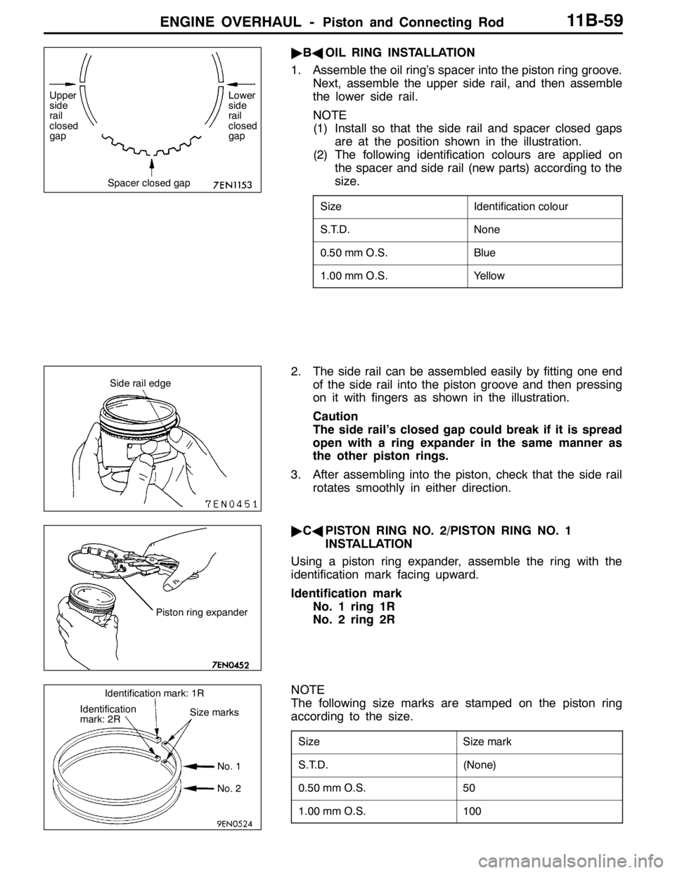
"BAOIL RING INSTALLATION
1. Assemble the oil ring’s spacer into the piston ring groove.
Next, assemble the upper side rail, and then assemble
the lower side rail.
NOTE
(1) Install so that the side rail and spacer closed gaps
are at the position shown in the illustration.
(2) The following identification colours are applied on
the spacer and side rail (new parts) according to the
size.
SizeIdentification colour
S.T.D.None
0.50 mm O.S.Blue
1.00 mm O.S.Yellow
2. The side rail can be assembled easily by fitting one end
of the side rail into the piston groove and then pressing
on it with fingers as shown in the illustration.
Caution
The side rail’s closed gap could break if it is spread
open with a ring expander in the same manner as
the other piston rings.
3. After assembling into the piston, check that the side rail
rotates smoothly in either direction.
"CAPISTON RING NO. 2/PISTON RING NO. 1
INSTALLATION
Using a piston ring expander, assemble the ring with the
identification mark facing upward.
Identification mark
No. 1 ring 1R
No. 2 ring 2R
NOTE
The following size marks are stamped on the piston ring
according to the size.
SizeSize mark
S.T.D.(None)
0.50 mm O.S.50
1.00 mm O.S.100
Spacer closed gap Upper
side
rail
closed
gapLower
side
rail
closed
gap
Side rail edge
Piston ring expander
Identification
mark: 2RSize marks
No. 1
No. 2 Identification mark: 1R
Page 514 of 1449

ENGINE OVERHAUL -Piston and Connecting Rod11B-60
"DAPISTON AND CONNECTING ROD ASSEMBLY
INSTALLATION
1. Apply sufficient engine oil on the piston ring’s periphery,
piston ring and oil ring.
2. Align the piston ring and oil ring (side rail, spacer) closed
gap positions as shown in the illustration.
3. Insert the piston and connecting rod assembly from the
top of the cylinder so that the front mark (arrow) on the
piston’s front face faces the camshaft sprocket side.
4. Securely hold the piston ring with a ring band, and insert
the piston and connecting rod assembly.
Caution
(1) The piston ring could break if tapped in with force.
(2) Make sure not to contact the oil jet when tapping
in.
"EACONNECTING ROD BEARING INSTALLATION
When replacing the bearing, use the following procedure to
select and assemble the bearing.
1. Measure the diameter of the crankshaft pin, and confirm
the class shown below.
When using a spare part, each identification colour is
painted at the position shown in the illustration.
2. The identification marks of the connecting rod bearings
are attached at the position shown in the illustration.
Crankshaft pin sectionConnect-
ing rod
bearing
ClassProduct
identifica-
tion colourSpare
part iden-
tification
colourDiameter mmIdentifica-
tion mark
1NoneYellow44.995 - 45.0000
2NoneNone44.985 - 44.9951
3NoneWhite44.980 - 44.9852
3. Select the bearing from the above table according to
the identification confirmed in steps 1 and 2.
Example of selecting bearing
If the measured outer diameter of the crankshaft pin is
44.996 mm, Class 1 applies, and the spare part
identification colour is yellow. Thus, select a bearing with
identification mark 0.
Side rail No. 1 ring
Side rail
No. 2 ring spacer
Piston pin
No. 4
No. 2
No. 3 No. 1
Identification
mark