Page 92 of 1575
Piston pin- to- connecting rod interference
- 0.033 ~ - 0.016mm ( - 0.0013 ~ - 0.0006in.)
REASSEMBLY
a.Thoroughly clean all parts before reassembling.
b. Before installing the parts, apply fresh engine oil to all sliding and rotating surfaces.
c. Replace all gaskets, O - rings and oil seals with new parts.
1. Assemble the piston and the connecting rod.
(1) Use a hydraulic press for installation.
(2) The piston front mark(A) and the connecting rod front mark must face the timing belt side of the engine.
2.Install piston rings.
(1) Install the oil ring spacer and 2 side rails by hand.
(2) Using a piston ring expander, install the 2 compression rings with the code mark facing upward.
(3) Position the piston rings so that the ring ends are as shown.
3.Install the connecting rod bearings.
(1) Align the bearing(A) claw with the groove of the connecting rod or connecting rod cap(B).
(2) Install the bearings(A) in the connecting rod and connecting rod cap(B).
Page 95 of 1575

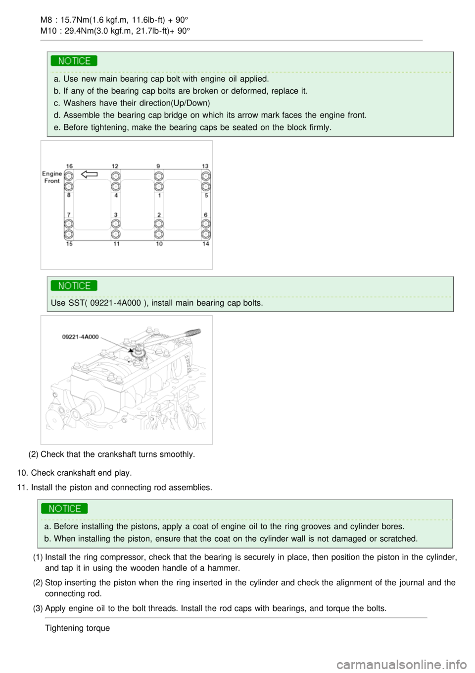
M8 : 15.7Nm(1.6 kgf.m, 11.6lb- ft) + 90°
M10 : 29.4Nm(3.0 kgf.m, 21.7lb- ft)+ 90°
a.Use new main bearing cap bolt with engine oil applied.
b. If any of the bearing cap bolts are broken or deformed, replace it.
c. Washers have their direction(Up/Down)
d. Assemble the bearing cap bridge on which its arrow mark faces the engine front.
e. Before tightening, make the bearing caps be seated on the block firmly.
Use SST( 09221 - 4A000 ), install main bearing cap bolts.
(2) Check that the crankshaft turns smoothly.
10. Check crankshaft end play.
11. Install the piston and connecting rod assemblies.
a.Before installing the pistons, apply a coat of engine oil to the ring grooves and cylinder bores.
b. When installing the piston, ensure that the coat on the cylinder wall is not damaged or scratched.
(1) Install the ring compressor, check that the bearing is securely in place, then position the piston in the cylinder,
and tap it in using the wooden handle of a hammer.
(2) Stop inserting the piston when the ring inserted in the cylinder and check the alignment of the journal and the
connecting rod.
(3) Apply engine oil to the bolt threads. Install the rod caps with bearings, and torque the bolts.
Tightening torque
Page 97 of 1575
(1)Make clean the sealing face before assembling two parts.
a.Remove harmful foreign materials on the sealing face before applying sealant
b. Apply sealant to the inner threads of the bolt holes.
(2) Assembling rear oil seal case, the liquid sealant TB1217H should be applied to the rear oil seal case.
The part must be assembled within 5 minutes after sealant was applied.
13. Using SST(09231- 33000), install rear oil seal after applying engine oil on the rip of the oil seal.
14. Install the oil pump case.
15. Install upper oil pan.
(1) Using a gasket scraper, remove all the old packing material from the gasket surfaces.
(2) Before assembling the oil pan, the liquid sealant TB1217H should be applied on upper oil pan.
The part must be assembled within 5 minutes after the sealant was applied.
Page 103 of 1575
2007 > 2.7L V6 GASOLINE >
REMOVAL
WATER PUMP
1. Drain the engine coolant.
System is under high pressure when the engine is hot. To avoid danger of releasing scalding engine coolant,
remove the cap only when the engine is cool.
2. Remove drive belt(A).
3.Remove the timing belt.
4. Remove the water pump(A) and gasket(B).
WATER TEMPERATURE CONTROL ASSEMBLY
1.Drain the engine coolant.
2. Remove the air cleaner assembly.
3. Disconnect the radiator upper and lower hose(A, B).
Page 104 of 1575
4.Disconnect the ECT(Engine Coolant Temperature) sensor connector.
5. Remove the coolant hose related to the heater hoses and the ECT(Engine Coolant Temperature) system.
6. Remove wiring protector.
7. Remove water temperature control assembly(A) and the gaskets(B).
8.Remove the water pipe(A).
THERMOSTAT
Removal of the thermostat would have an adverse effect, causing a lowering of cooling efficiency. Do not remove
the thermostat, even if the engine tends to overheat.
1. Drain engine coolant so its level is below thermostat.
2. Remove the coolant inlet pitting(A) and the thermostat(B).
Page 105 of 1575
RADIATOR
1.Drain the engine coolant.
2. Remove the radiator grille upper cover(A).
3.Remove the radiator support upper member assembly(A) for convenience sake.
The bottom side bolt(A) which can be seen after removing the under cover should be loosened for removal of
the radiator support upper member assembly.
Page 108 of 1575
Clean the contacting face before assembling.
2. Install the timing belt.
3. Install drive belt(A).
4.Fill with engine coolant.
5. Start engine and check for leaks.
6. Recheck engine coolant level.
WATER TEMPERATURE CONTROL ASSEMBLY
1.Install the water pipe(A).
Tightening torque
16.7 ~ 19.6Nm (1.7 ~ 2.0kgf.m, 12.3 ~ 14.5lb- ft)
2.Install the water temperature control assembly(A) with a new gasket(B).
Tightening torque
Page 109 of 1575
29.4 ~ 41.2Nm(3.0 ~ 4.2kgf.m, 21.7 ~ 30.4lb- ft
Use new O - rings and wet them with water or coolant when reassembling.
3. Install the wiring protector.
4. Connect the heater hose and ECT hose.
5. Connect the ECT sensor connector.
6. Connect the radiator upper and the lower hose(A).
7.Install the air cleaner assembly.
8. Fill with engine coolant.
9. Start engine and check for leaks.
10. Recheck engine coolant level.
THERMOSTAT
1.Place thermostat(B) in coolant inlet pitting(A).
Install the thermostat with the jiggle valve upward.