Page 63 of 1575
2007 > 2.7L V6 GASOLINE >
REMOVAL
a.Use fender covers to avoid damaging painted surfaces.
b. To avoid damage, unplug the wiring connectors carefully while holding the connector portion.
a.Mark all wiring and hoses to avoid misconnection.
1. Remove the engine cover.
2. Disconnect the neagative terminal from the battery and remove the battery(A).
3.Remove the intake air hose and air cleaner assembly.
(1) Disconnect the MAF connector(A).
(2) Disconnect the breather hose(B) from air cleaner hose.
(3) Remove the intake air hose and air cleaner assembly(C).
4.Remove the battery tray(A).
Page 64 of 1575
5.Remove the under cover.
6.Drain the engine coolant.
7. Remove the upper radiator hose(A) and lower radiator hose(B).
8.Remove the transaxle oil cooler hoses(A/T vehicles only).
9. Remove the fuel inlet hose(A) from the delivery pipe.
10. Disconnect the engine wiring harness connectors.
Page 67 of 1575
(10)Disconnect the bank 1 CMP sensor connector(A).
11.Disconnect engine wiring.
(1) Remove the engine room fuse and relay box cover(A).
(2) Disconnect the PCM connectors(B).
(3) Disconnect the FAM connectors(C)(Refer to HA group).
(4)Unscrew the FAM mounting bolts(D - 3EA) and take the FAM(E) out of the splash shield(F).
(5) Disconnect the connector(G) from the splash shield(B).
Page 69 of 1575
The bottom side bolt(A) which can be seen after removing the under cover should be loosened for removal of
the radiator support upper member assembly.
18.Drain engine oil.
19. Remove the brake caliper.(Refer to DS group).
20. Disconnect the air conditioning compressor hoses.(Refer to HA group).
21. Remove the front wheels and tires.(Refer to DS group).
22. Remove the brake caliper hub nut.(Refer to DS group).
23. Remove the tie rod end ball joint from the knuckle.(Refer to DS group)
24. Remove the driver shaft and the stabilizer bar link(Refer to SS group).
25. Remove the front muffler(A).
26.Using a floor jack, support the engine and transaxle assembly.
After removing the sub frame mounting bolt , the engine and transaxle assembly may fall downward, and so
support them securely with floor jack.
Page 70 of 1575
support them securely with floor jack.
Verify that the hoses and connectors are disconnected before removing the engine and transaxle assembly.
27. Remove the engine mounting bracket(A) and the ground(B).
28.Remove the transaxle insulator mounting bolt(A).
Remove the ECM(Electronic Controlled Mounting) nuts and the solenoid valve connector for A/T vehicles.
29. Supporting the engine and transaxle assembly with a jack, remove the assembly from the vehicle by loosening the
sub frame mounting bolts and lifting up the vehicle slowly.
When removing the engine and transaxle assembly, be careful not to damage any surrounding parts or body
components.
Front
Real
Page 71 of 1575
INSTALLATION
Installation is in the reverse order of removal.
Perform the following :a. Adjust the shift cable.
b. Refill the engine with engine oil.
c. Refill the transaxle with fluid.
d. Refill the radiator with engine coolant.
e. Bleed air from the cooling system with the heater valve open.
f. Clean the battery posts and cable terminals with sandpaper assemble them, then apply grease to prevent
corrosion.
g. Inspect for fuel leakage.
After assembling the fuel line, turn on the ignition switch (do not operate the starter) so that the fuel pump runs for
approximately two seconds and fuel line pressurizes.
Repeat this operation two or three times, then check for fuel leakage at any point in the fuel line.
Page 75 of 1575
2007 > 2.7L V6 GASOLINE >
REMOVAL
1.Remove the drive plate(A).
2.Remove the rear plate(A).
3.Remove timing belt.
4. Remove intake manifold.
5. Remove exhaust manifold.
6. Remove generator from engine.(Refer to 'ST' group).
7. Remove power steering pump from engine.(Refer to 'HA' group).
8. Remove cylinder head.
9. Remove A/C compressor from engine.(Refer to 'EE' group).
10. Remove water pump assembly.
INSTALLATION
1.Install the water pump.
2. Install the air conditioning compressor.(Refer to 'HA' group).
3. Install the cylinder head.
4. Install the power steering pump.(Refer to 'ST' group).
5. Install the generator.
6. Install the intake manifold.
7. Install the exhaust manifold.
8. Install the timing belt.
9. Install the rear plate(A).
Tightening torque
Page 84 of 1575

(6)If the plastigage measures too wide or too narrow, remove the upper half of the bearing, install a new,
complete bearing with the same color mark (select the color as shown in the next column), and recheck the
clearance.
Do not file, shim, or scrape the bearings or the caps to adjust clearance.
(7) If the plastigage shows the clearance is still incorrect, try the next larger or smaller bearing (the color listed
above or below that one), and check clearance again.
If the proper clearance cannot be obtained by using the appropriate larger or smaller bearings, replace the
crankshaft and start over.
If the marks are indecipherable because of an accumulation of dirt and dust, do not scrub them with a wire
brush or scraper. Clean them only with solvent or detergent.
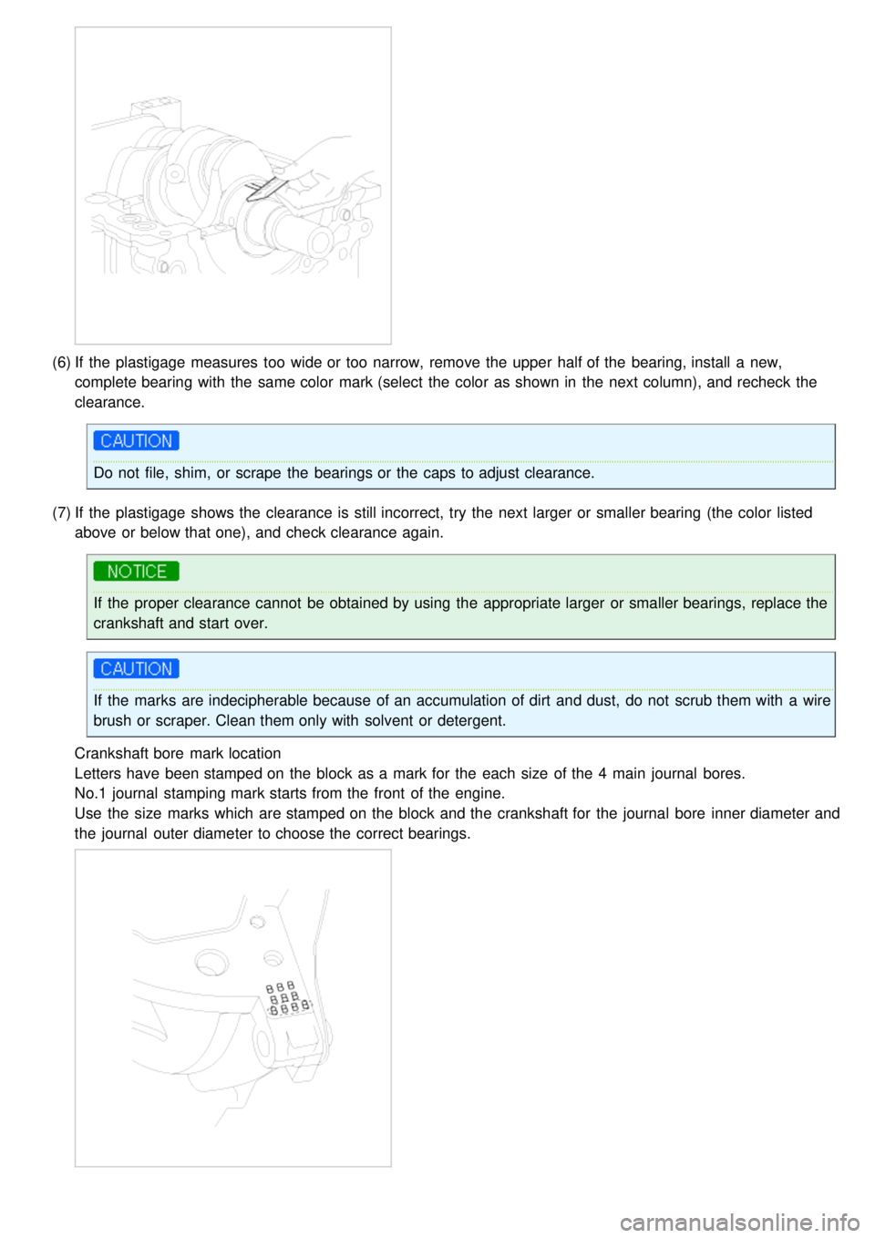
Crankshaft bore mark location
Letters have been stamped on the block as a mark for the each size of the 4 main journal bores.
No.1 journal stamping mark starts from the front of the engine.
Use the size marks which are stamped on the block and the crankshaft for the journal bore inner diameter and
the journal outer diameter to choose the correct bearings.