2007 KIA CARNIVAL seats
[x] Cancel search: seatsPage 42 of 1575

2.Reprocess the valve guide hole for the oversized valve guide newly installed.
3. Using the SST(09221- 3F100A/B), insert the valve guide in the upside of the cylinder head assembly. Be aware of
the difference in length between the intake and the exhaust valve guides.
Specification
Intake valve guide: 45.8 ~ 46.2mm(1.8031 ~ 1.8189in.)
Exhaust valve guide: 46.8 ~ 47.2mm(1.8425 ~ 1.8583in.)
4.After installing the valve guides, insert new valves and check the clearance between the valve stems and the valve
guides.
5. After replacing the valve guides, check if they are properly installed with the valve seats. Reprocess valve seats if
necessary.
INSTALLATION
a.Thoroughly clean all parts to be assembled.
b. Always use a new head and manifold gasket.
c. The cylinder head gasket is a metal gasket. Take care not to bend it.
d. Rotate the crankshaft to set the No.1 cylinder piston at TDC.
1. After putting the cylinder head gasket on the cylinder block, install the cylinder head.
Page 55 of 1575

If the margin thickness is less than the specification, replace the valve.
Specification
Intake : 1.0mm(0.0394in.)
Exhaust : 1.3mm(0.0512.)
(4)Check the valve length.
Length
Intake : 110.1mm(4.3346in)
Exhaust : 111.1mm(4.3740in)
(5) Check the surface of the valve stem tip for wear.
If the valve stem tip is worn, replace the valve.
3. Inspect valve seats
(1) Check the valve seat for evidence of overheating or improper contact with the valve face.
If the valve seat is worn, replace cylinder head.
(2) Before reconditioning the seat, check the valve guide for wear. If the valve guide is worn, replace the valve
guide first.
(3) Recondition the valve seat with a valve seat grinder or cutter. The valve seat contact width should be within
specifications and centered on the valve face.
4. Inspect valve springs.
(1) Using a steel square, measure the out - of- square of the valve spring.
(2) Using vernier calipers, measure the free length of the valve spring.
Valve spring
[Standard]
Free height : 46.8mm (1.8425in.)
Out- of- square : 1.5° or less
Page 185 of 1575

STARTER BRUSH HOLDER TEST
1.Check that there is no continuity between the (+) brush holder (A) and ( - ) brush holder (B). If there is no continuity,
replace the brush holder assembly.
2.Pry back each brush spring (A) with a screwdriver, then position the brush (B) about halfway out of its holder, and
release the spring to hold it there.
3.Install the armature in the housing, and install the brush holder. Next, pry back each brush spring again, and push
the brush down until it seats against the commutator, then release the spring against the end of the brush.
To seat new brushes, slip a strip of #500 or #600 sandpaper, with the grit side up, between the commutator
and each brush, and smoothly rotate the armature. The contact surface of the brushes will be sanded to the
same contour as the commutator.
Page 445 of 1575

2007 > 2.7L V6 GASOLINE >
TROUBLESHOOTING
Symptom Possible cause Remedy
Vehicle pulls to one side Scoring of driveshaft ball joint
Wear, rattle or scoring of wheel bearing
Defective front suspension and steering Replace
Replace
Adjust or replace
Vibration Wear, damage or bending of driveshaft
Driveshaft rattle and worn hub splines
Wear, rattle or scratching of wheel bearing Replace
Replace
Replace
Shimmy Improper wheel balance
Bent wheel
Defective front suspension and steering Adjust or replace
Replace
Adjust or replace
Excessive noise Wear, damage or bending of driveshaft
Driveshaft rattle and worn hub splines
Driveshaft rattle and worn side gear splines
Wear, rattle or galling of wheel bearing
Loose hub nut
Defective front suspension and steering Replace
Replace
Replace
Replace
Adjust or replace
Adjust or replace
Bent cage Cage damaged by improper handling or tool usage Replace bearing
Galling Metal smears on roller end due to overheating,
incorrect lubricant or overloading Replace bearing
Check seals, check for
proper lubrication
Cracked inner race Race cracked due to improper fit, cocking or poor bearing
seats Replace bearing
Etching Bearing surfaces appear gray or grayish black
in color accompanied by material etched
away usually at roller spacing Replace bearing
Check seals, check for
proper lubrication
Brinelling Surface indentations on race surface caused by rollers
being under impact loading or vibration while the bearing
is not rotating Replace bearing
Heat discoloration Heat discoloration is dark blue resulting
from overload or no lubricant (Yellow or brown color is
normal) Replace bearing
Check seals and other parts
Fatigue spalling Flaking of surface metal resulting from fatigue Replace bearing
Clean all related parts
Page 792 of 1575

c.Store the removed airbag on secure, flat surface away from any high heat source (exceeding 85°C/185°F).
d. Never perform electrical inspections to the airbags, such as measuring resistance.
e. Do not position yourself in front of the airbag assembly during removal, inspection, or replacement.
f. Refer to the scrapping procedures for disposal of the damaged airbag.
g. Be careful not to bump or impact the SRS unit or the side impact sensors whenever the ignition switch is ON, wait
at least three minutes after the ignition switch is turned OFF before begin work.
h. During installation or replacement, be careful not to bump (by impact wrench, hammer, etc.) the area around the
SRS unit and the side impact sensor. The airbags could accidentally deploy and cause damage or injury.
i. After a collision in which the airbags were deployed, replace the front airbags and the SRS unit. After a collision in
which the side airbag was deployed, replace the side airbag, the front impact sensor and side impact sensor on
the side where the side airbag deployed and the SRS unit. After a collision in which the airbags or the side air
bags did not deploy, inspect for any damage or any deformation on the SRS unit and the side impact sensors. If
there is any damage, replace the SRS unit, the front impact sensor and/or the side impact sensors.
j. Do not disassemble the SRS unit, the front impact sensor or the side impact sensors
k. Turn the ignition switch OFF, disconnect the battery negative cable and wait at least three minutes before
beginning installation or replacement of the SRS unit.
l. Be sure the SRS unit, the front impact sensor and side impact sensors are installed securely with the mounting
bolts.
m. Do not spill water or oil on the SRS unit,or the front impact sensor or the side impact sensors and keep them
away from dust.
n. Store the SRS unit, the front impact sensor and the side impact sensors in a cool (less than 40°C/104°F) and dry
(less than 80% relative humidity, no moisture) area.
Wiring Precautions
SRS wiring can be identified by special yellow outer covering (except the SRS circuits under the front seats).
Observe the instructions described in this section.
a. Never attempt to modify, splice, or repair SRS wiring.
If there is an open or damage in SRS wiring, replace the harness.
Page 1178 of 1575

2007 > 2.7L V6 GASOLINE >
REPLACEMENT
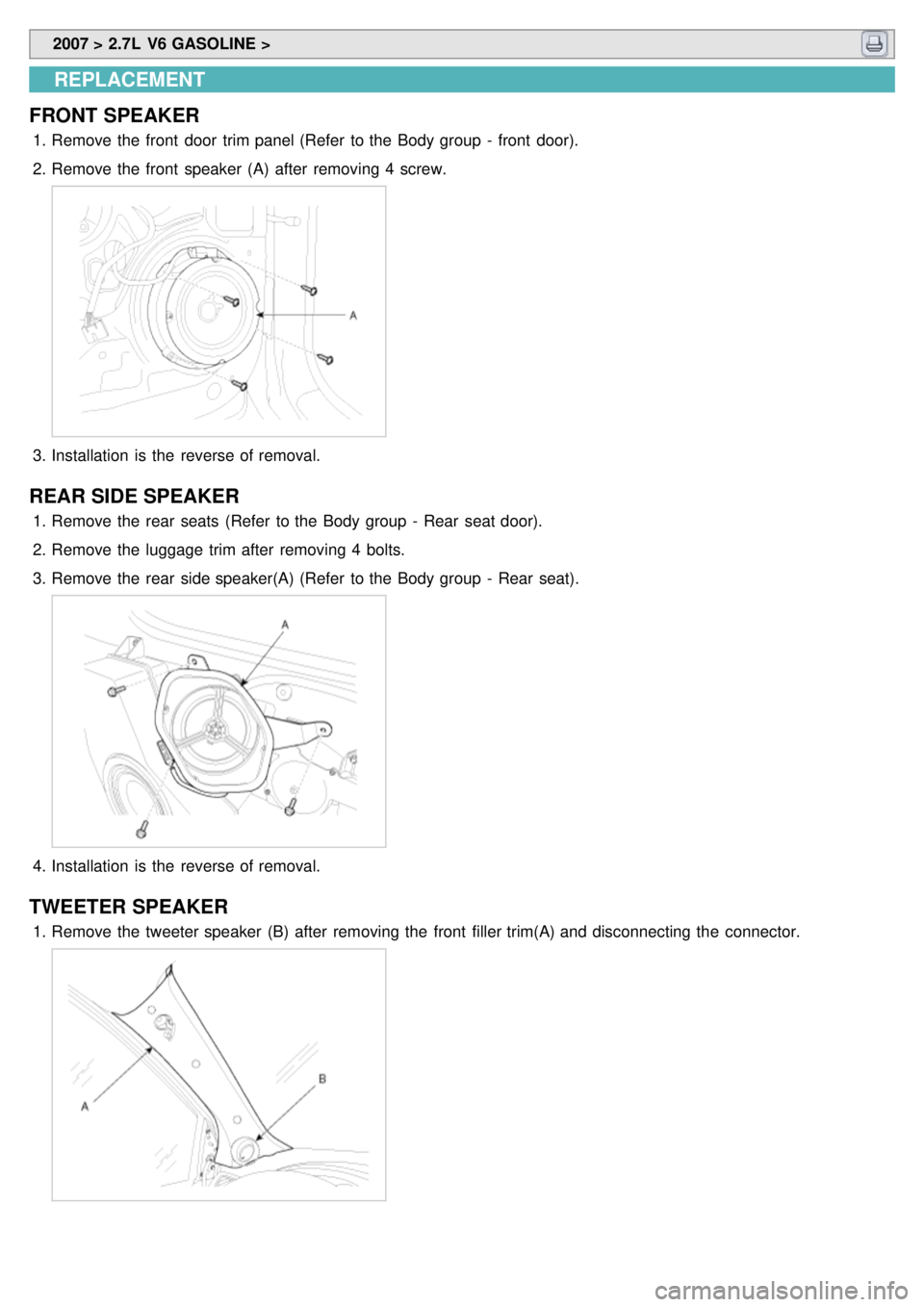
FRONT SPEAKER
1. Remove the front door trim panel (Refer to the Body group - front door).
2. Remove the front speaker (A) after removing 4 screw.
3.Installation is the reverse of removal.
REAR SIDE SPEAKER
1.Remove the rear seats (Refer to the Body group - Rear seat door).
2. Remove the luggage trim after removing 4 bolts.
3. Remove the rear side speaker(A) (Refer to the Body group - Rear seat).
4.Installation is the reverse of removal.
TWEETER SPEAKER
1.Remove the tweeter speaker (B) after removing the front filler trim(A) and disconnecting the connector.
Page 1179 of 1575

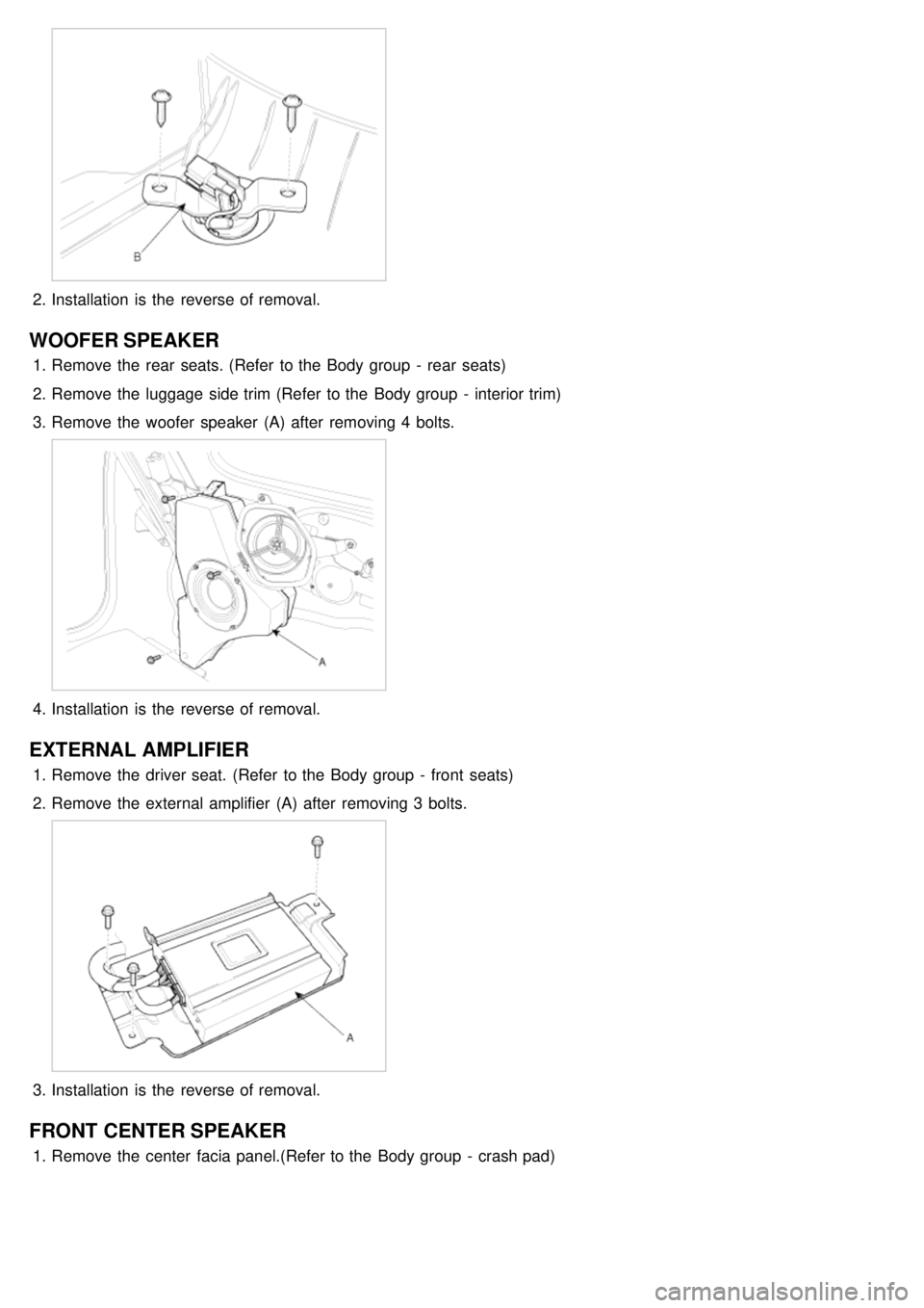
2.Installation is the reverse of removal.
WOOFER SPEAKER
1.Remove the rear seats. (Refer to the Body group - rear seats)
2. Remove the luggage side trim (Refer to the Body group - interior trim)
3. Remove the woofer speaker (A) after removing 4 bolts.
4.Installation is the reverse of removal.
EXTERNAL AMPLIFIER
1.Remove the driver seat. (Refer to the Body group - front seats)
2. Remove the external amplifier (A) after removing 3 bolts.
3.Installation is the reverse of removal.
FRONT CENTER SPEAKER
1.Remove the center facia panel.(Refer to the Body group - crash pad)
Page 1225 of 1575

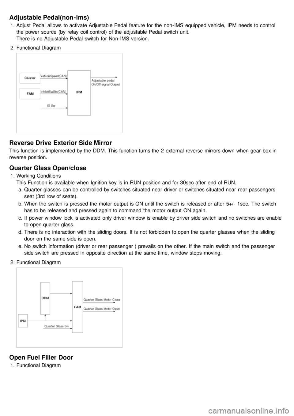
Adjustable Pedal(non-ims)
1.Adjust Pedal allows to activate Adjustable Pedal feature for the non- IMS equipped vehicle, IPM needs to control
the power source (by relay coil control) of the adjustable Pedal switch unit.
There is no Adjustable Pedal switch for Non- IMS version.
2. Functional Diagram
Reverse Drive Exterior Side Mirror
This function is implemented by the DDM. This function turns the 2 external reverse mirrors down when gear box in
reverse position.
Quarter Glass Open/close
1.Working Conditions
This Function is available when Ignition key is in RUN position and for 30sec after end of RUN.
a. Quarter glasses can be controlled by switches situated near driver or switches situated near rear passengers
seat (3rd row of seats).
b. When the switch is pressed the motor output is ON until the switch is released or after 5+/- 1sec. The switch
has to be released and pressed again to command the motor output ON again.
c. If power window lock is activated only driver window is enable by driver side switch and no switches are enable
to open quarter glass.
d. There is no interaction with the sliding doors. It is not forbidden to open the quarter glasses when the sliding
door on the same side is open.
e. No switch information (driver or rear passenger ) prevails on the other. If the main switch and the passenger
side switch are pressed in opposite direction at the same time, window stops moving.
2. Functional Diagram
Open Fuel Filler Door
1.Functional Diagram