Page 980 of 1575
CIRCUIT DIAGRAM (YAW-RATE & LATERAL G SENSOR)
Page 986 of 1575

2007 > 2.7L V6 GASOLINE >
DESCRIPTION
GENERAL DATA
The steering angle speed sensor detects the angle of the steering wheel in order to which direction a user chooses.
MEASUREING PRINCIPLE
A non contact, analog angle sensor carrying out absolute measuring by the use of the Anisotropic - Magneto- Resistive
effect (AMR).Measuring of the absolute angle by means of a toothed measuring gear with magnetic properties in
combination with different ratios. Corresponding AMR elements that change their electrical resistance according to the
magnetic field direction detect the angle position of the measuring gears.A micro- controller decodes the measured
voltage signals after A/D converting with the help of a mathematical function. Output of the digital angle value and
velocity via CAN- interface.
SPECIFICATION
Description Specification
Operating voltage 8~16 V
Operating temperature - 40 ~ 85 °C
Current consumption Max.150 mA
Steering angle velocity Max. ±2000 °/sec
Connection delay time t < 200 ms
Reverse voltage - 13.5 V
Measuring range Angle
- 780 ° ~ 779 °
Angular velocity 0~ 1016 °/s
Nonlinearity angle - 2.5 ° ~ +2.5 °
Hysteresis angle 0 ° ~ 5 °
Rotational friction torque measuring 10 °/s
CIRCUIT DIAGRAM( STEERING WHEEL SPEED ANGLE SENSOR)
STEERING ANGLE SENSOR (SAS) calibration
1.PURPOSE OF calibration
a. On vehicle control, an ESP analyzes the intention of the driver.
b. An ESP recognizes a steering angle which a driver rotates through the steering angle sensor.
Page 1188 of 1575
2007 > 2.7L V6 GASOLINE >
CIRCUIT DIAGRAM
Page 1212 of 1575
Functions
Exterior Lighting Functions
The exterior lighting function has to provide the lighting and signalling of the vehicle; it monitors different available
lights in front or at the back of the vehicle: a. Park and Tail lamps (with Side marker lamps),
b. License plate lamps,
c. Head lamps Low Beam,
d. Head lamps High Beam,
e. Front and Rear fog lamps (with the Rear fog lamp switch indicator),
f. Stop lamps,
g. Backup lamps,
h. Turn signal and side repeater lamps.
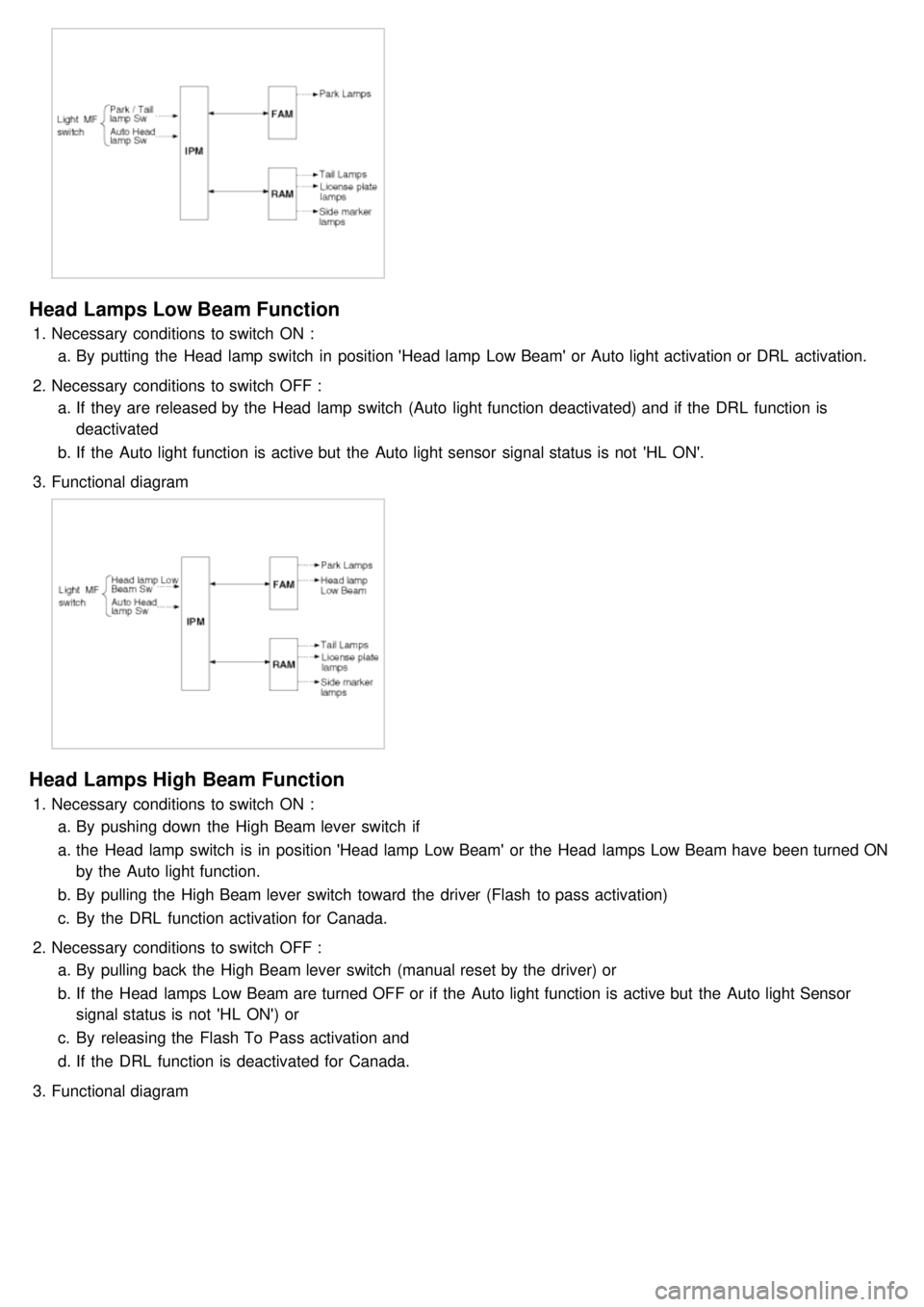
Park/tail Lamps Function
1.Necessary conditions to switch ON :
a. By putting the Head lamp switch in position 'Park and Tail lamp' or 'Head lamp Low Beam' or Auto light
activation or DRL activation
2. Necessary conditions to switch OFF :
a. If they are released by the Head lamp switch (Auto light function deactivated) and if DRL function is deactivated
b. If the Auto light function is active but the Auto light Sensor signal status is OFF or Battery Saver function is
active.
3. Functional diagram
Page 1213 of 1575

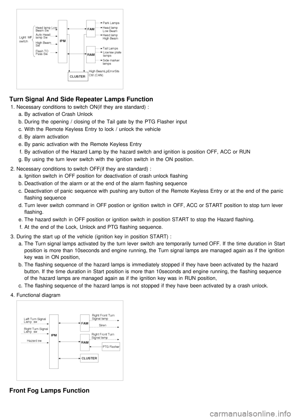
Head Lamps Low Beam Function
1.Necessary conditions to switch ON :
a. By putting the Head lamp switch in position 'Head lamp Low Beam' or Auto light activation or DRL activation.
2. Necessary conditions to switch OFF :
a. If they are released by the Head lamp switch (Auto light function deactivated) and if the DRL function is
deactivated
b. If the Auto light function is active but the Auto light sensor signal status is not 'HL ON'.
3. Functional diagram
Head Lamps High Beam Function
1.Necessary conditions to switch ON :
a. By pushing down the High Beam lever switch if
a. the Head lamp switch is in position 'Head lamp Low Beam' or the Head lamps Low Beam have been turned ON
by the Auto light function.
b. By pulling the High Beam lever switch toward the driver (Flash to pass activation)
c. By the DRL function activation for Canada.
2. Necessary conditions to switch OFF :
a. By pulling back the High Beam lever switch (manual reset by the driver) or
b. If the Head lamps Low Beam are turned OFF or if the Auto light function is active but the Auto light Sensor
signal status is not 'HL ON') or
c. By releasing the Flash To Pass activation and
d. If the DRL function is deactivated for Canada.
3. Functional diagram
Page 1214 of 1575

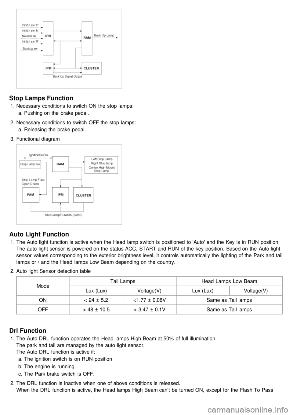
Turn Signal And Side Repeater Lamps Function
1.Necessary conditions to switch ON(if they are standard) :
a. By activation of Crash Unlock
b. During the opening / closing of the Tail gate by the PTG Flasher input
c. With the Remote Keyless Entry to lock / unlock the vehicle
d. By alarm activation
e. By panic activation with the Remote Keyless Entry
f. By activation of the Hazard Lamp by the hazard switch and ignition is position OFF, ACC or RUN
g. By using the turn lever switch with the ignition switch in the ON position.
2. Necessary conditions to switch OFF(if they are standard) :
a. Ignition switch in OFF position for deactivation of crash unlock flashing
b. Deactivation of the alarm or at the end of the alarm flashing sequence
c. Deactivation of panic sequence with pushing any button of the Remote Keyless Entry or at the end of the panic
flashing sequence
d. Turn lever switch command in OFF postion or ignition switch in OFF, ACC or START position to stop turn lever
flashing.
e. The hazard switch in OFF position or ignition switch in position START to stop the Hazard flashing.
f. At the end of the Lock, Unlock and PTG flashing sequence.
3. During the start up of the vehicle (ignition key in position START) :
a. The Turn signal lamps activated by the turn lever switch are temporarily turned OFF. If the time duration in Start
position is more than 10seconds and engine running, the Turn signal lamps are managed again as if the ignition
key was in ON position,
b. The flashing sequence of the hazard lamps is immediately stopped if they have been activated by the hazard
button. If the time duration in Start position is more than 10seconds and engine running, the flashing sequence
of the hazard lamps are managed again as if the ignition key was in RUN position,
c. The flashing sequence of the hazard lamps is not stopped if they have been activated by a crash unlock.
4. Functional diagram
Front Fog Lamps Function
Page 1215 of 1575
1.Necessary conditions to switch ON :
a. By using the stalk: Head lamp switch in position 'Head lamp Low Beam' and Front Fog lamp sw ON
b. When Auto light function activated and Auto light Sensor signal status is 'HL ON' and Front Fog lamp sw ON
2. Necessary conditions to switch OFF :
a. When Auto light function activated and Auto light Sensor signal status is not ON
b. When Front fog lamp sw OFF.
3. Functionnal Diagram
Backup Lamps Function
1.Necessary conditions to switch ON :
a. When inhibit sw 'R' read by FAM is active and transmitted to RAM by CAN signal.
2. Necessary conditions to switch OFF :
a. When inhibit sw 'R' read by FAM is not active and transmitted to RAM by CAN signal.
3. Functional diagram
Page 1216 of 1575

Stop Lamps Function
1.Necessary conditions to switch ON the stop lamps:
a. Pushing on the brake pedal.
2. Necessary conditions to switch OFF the stop lamps:
a. Releasing the brake pedal.
3. Functional diagram
Auto Light Function
1.The Auto light function is active when the Head lamp switch is positioned to 'Auto' and the Key is in RUN position.
The auto light sensor is powered on the status ACC, START and RUN of the key position. Based on the Auto light
sensor values corresponding to the exterior brightness level, it controls automatically the lighting of the Park and tail
lamps or / and the Head lamps Low Beam depending on the country.
2. Auto light Sensor detection table
Mode Tail Lamps
Head Lamps Low Beam
Lux (Lux) Voltage(V) Lux (Lux)Voltage(V)
ON < 24 ± 5.2 <1.77 ± 0.08V Same as Tail lamps
OFF > 48 ± 10.5 > 3.47 ± 0.1V Same as Tail lamps
Drl Function
1.The Auto DRL function operates the Head lamps High Beam at 50% of full illumination.
The park and tail are managed by the auto light sensor.
The Auto DRL function is active if:
a. The ignition switch is on RUN position
b. The engine is running.
c. The Park brake switch is OFF.
2. The DRL function is inactive when one of above conditions is released.
When the DRL function is active, the Head lamps High Beam can't be turned ON, except for the Flash To Pass
activation.