Page 1226 of 1575
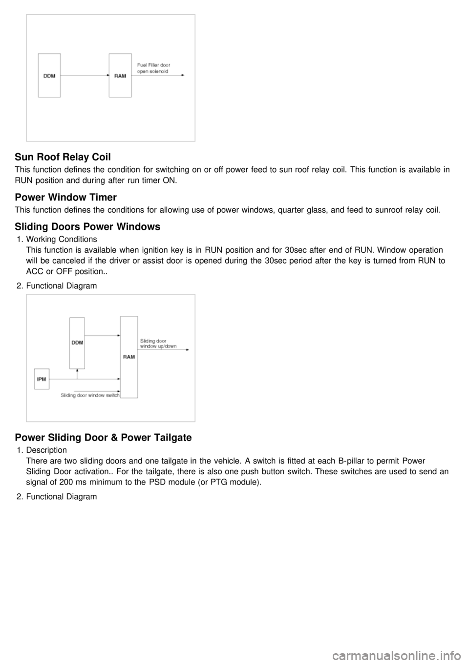
Sun Roof Relay Coil
This function defines the condition for switching on or off power feed to sun roof relay coil. This function is available in
RUN position and during after run timer ON.
Power Window Timer
This function defines the conditions for allowing use of power windows, quarter glass, and feed to sunroof relay coil.
Sliding Doors Power Windows
1.Working Conditions
This function is available when ignition key is in RUN position and for 30sec after end of RUN. Window operation
will be canceled if the driver or assist door is opened during the 30sec period after the key is turned from RUN to
ACC or OFF position..
2. Functional Diagram
Power Sliding Door & Power Tailgate
1.Description
There are two sliding doors and one tailgate in the vehicle. A switch is fitted at each B- pillar to permit Power
Sliding Door activation.. For the tailgate, there is also one push button switch. These switches are used to send an
signal of 200 ms minimum to the PSD module (or PTG module).
2. Functional Diagram
Page 1227 of 1575
Easy Access
1.Description
The easy access function permits automatic rearward movement of the driver seat when the key is removed from
the cylinder. Automatic forward movement of the driver seat will take place when the key is inserted into the
cylinder. This function will be enabled on IMS equipped vehicles when the AUTO button is pressed.
Inhibit Switch should be in P- Position for the Easy Access operation.
2. Functional Diagram
Driver Information
Cluster Indicators
1.The instument cluster indicators listed below are controlled by the In- Panel Module (IPM), Front Area Module
(FAM), or Rear Area Module (RAM) as applicable.
These indicators are:
a. Gearbox status
b. Oil pressure
c. Sediment fuel filter
d. Vacuum
e. Brake fluid
f. Washer fluid
g. Seat belt
h. Park brake
i. Charging voltage
j. Turn indicators
k. High beam
l. Front fog
m. Doors open
n. Tailgate open
o. Stop lamp failure front and rear
2. Functional Diagram
Page 1231 of 1575
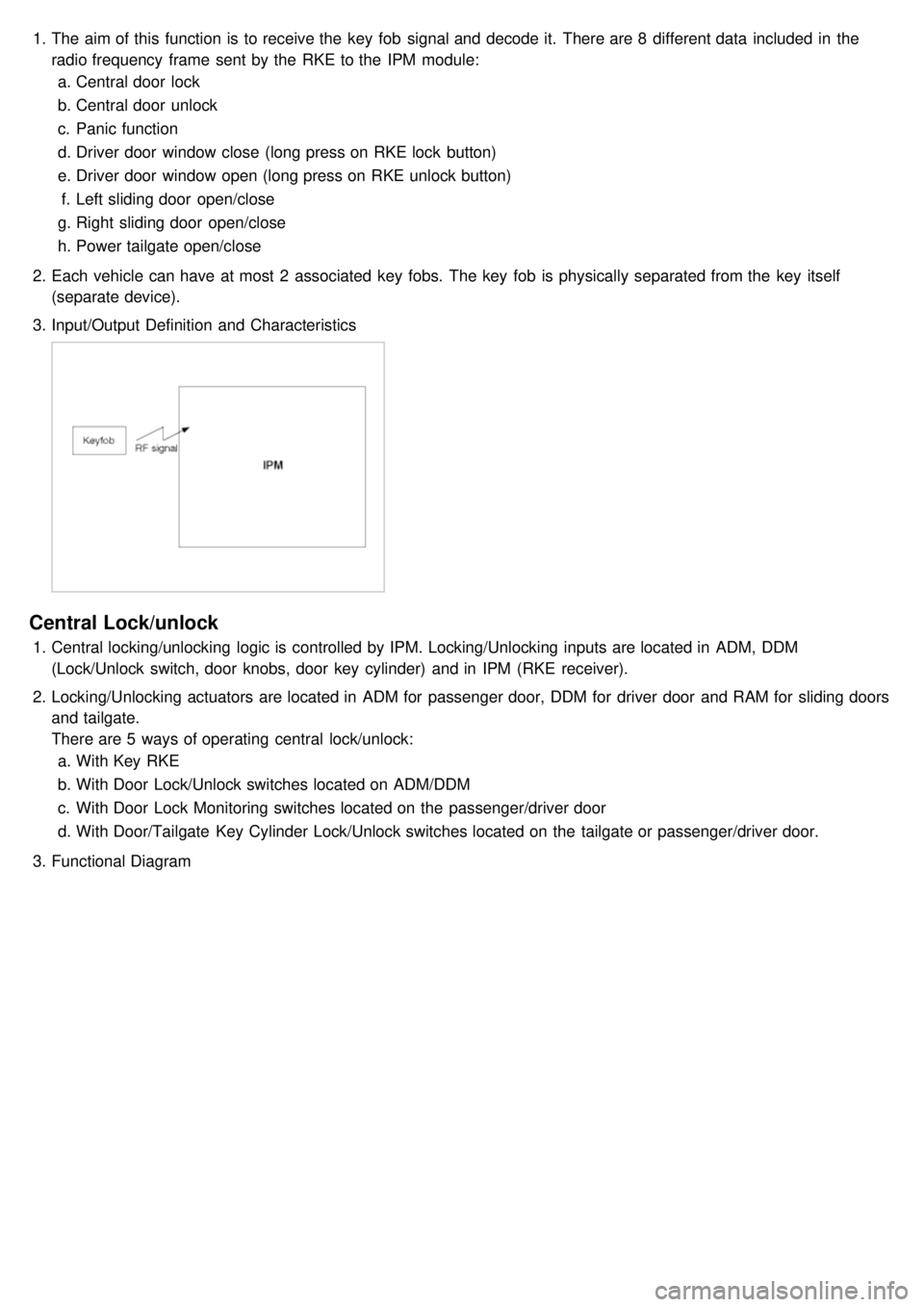
1.The aim of this function is to receive the key fob signal and decode it. There are 8 different data included in the
radio frequency frame sent by the RKE to the IPM module:
a. Central door lock
b. Central door unlock
c. Panic function
d. Driver door window close (long press on RKE lock button)
e. Driver door window open (long press on RKE unlock button)
f. Left sliding door open/close
g. Right sliding door open/close
h. Power tailgate open/close
2. Each vehicle can have at most 2 associated key fobs. The key fob is physically separated from the key itself
(separate device).
3. Input/Output Definition and Characteristics
Central Lock/unlock
1.Central locking/unlocking logic is controlled by IPM. Locking/Unlocking inputs are located in ADM, DDM
(Lock/Unlock switch, door knobs, door key cylinder) and in IPM (RKE receiver).
2. Locking/Unlocking actuators are located in ADM for passenger door, DDM for driver door and RAM for sliding doors
and tailgate.
There are 5 ways of operating central lock/unlock:
a. With Key RKE
b. With Door Lock/Unlock switches located on ADM/DDM
c. With Door Lock Monitoring switches located on the passenger/driver door
d. With Door/Tailgate Key Cylinder Lock/Unlock switches located on the tailgate or passenger/driver door.
3. Functional Diagram
Page 1232 of 1575
Key Reminder Unlock
1.Key reminder door unlock does not take into account the lock/unlock commands from RKE, key cylinder or door
lock switches. It only takes into account the state of the door lock monitoring switch, key reminder switch and door
open status in order to proceed with the unlock sequence or not.
2. Functional Diagram
Remote Keyless Entry Panic
1.Working Conditions
RKE panic function is only active when the key is out of key cylinder.
Once started, panic operation is not stopped when ignition key is inserted, ignition is ACC, RUN or START, or
door is opened or closed.
2. Functional Diagram
Page 1233 of 1575
Horn
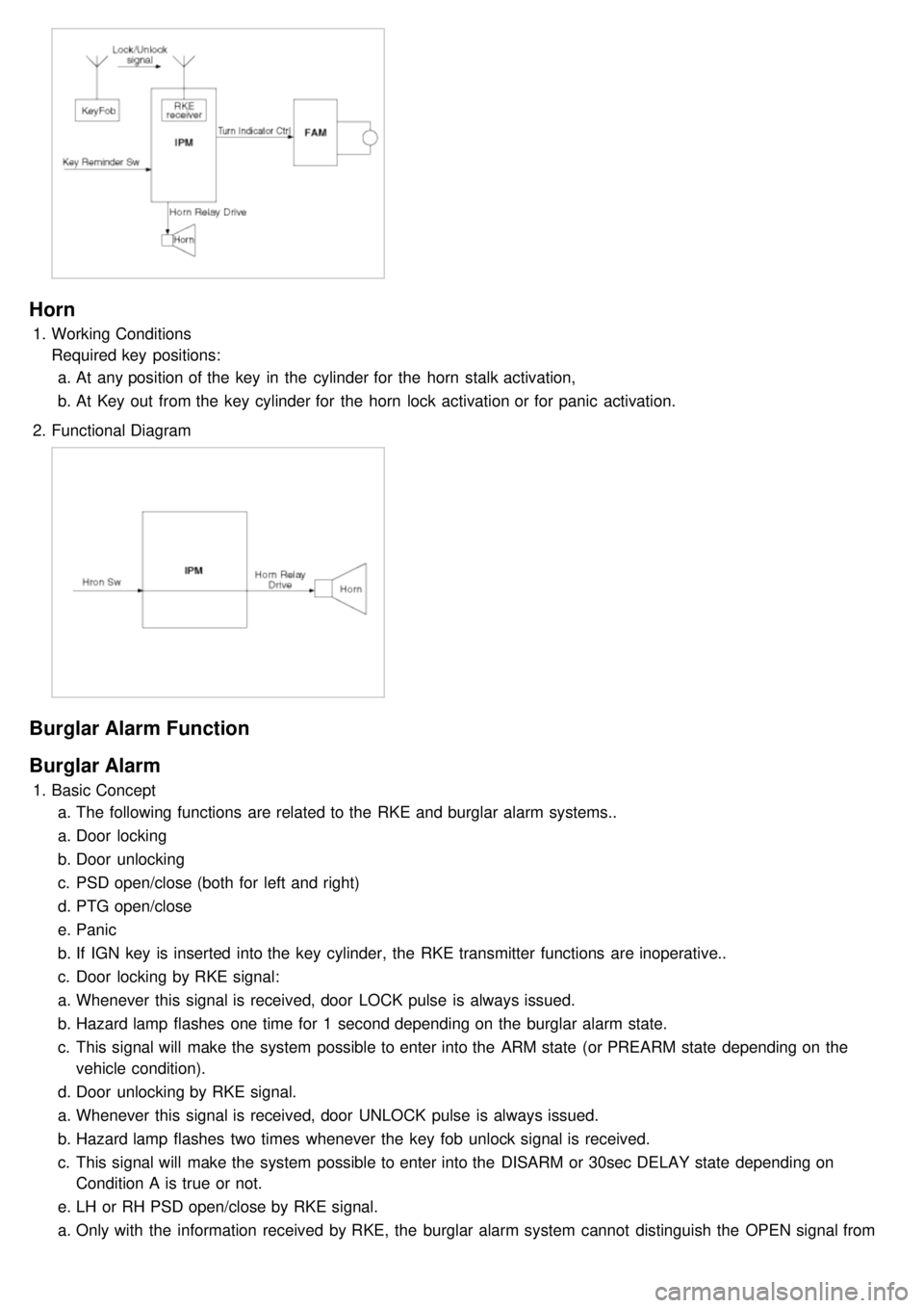
1.Working Conditions
Required key positions:
a. At any position of the key in the cylinder for the horn stalk activation,
b. At Key out from the key cylinder for the horn lock activation or for panic activation.
2. Functional Diagram
Burglar Alarm Function
Burglar Alarm
1.Basic Concept
a. The following functions are related to the RKE and burglar alarm systems..
a. Door locking
b. Door unlocking
c. PSD open/close (both for left and right)
d. PTG open/close
e. Panic
b. If IGN key is inserted into the key cylinder, the RKE transmitter functions are inoperative..
c. Door locking by RKE signal:
a. Whenever this signal is received, door LOCK pulse is always issued.
b. Hazard lamp flashes one time for 1 second depending on the burglar alarm state.
c. This signal will make the system possible to enter into the ARM state (or PREARM state depending on the
vehicle condition).
d. Door unlocking by RKE signal.
a. Whenever this signal is received, door UNLOCK pulse is always issued.
b. Hazard lamp flashes two times whenever the key fob unlock signal is received.
c. This signal will make the system possible to enter into the DISARM or 30sec DELAY state depending on
Condition A is true or not.
e. LH or RH PSD open/close by RKE signal.
a. Only with the information received by RKE, the burglar alarm system cannot distinguish the OPEN signal from
CLOSE signal.
Page 1234 of 1575
CLOSE signal.
b. RAM will pass this signal to LH PSD and RH PSD then the burglar alarm state is decided depending on the
vehicle condition.
f. PTG open/close
a. Only with the information received by RKE, the burglar alarm system cannot distinguish the OPEN signal from
CLOSE signal.
b. RAM will pass this signal to PTG module then the burglar alarm state is decided depending on the vehicle
condition.
g. Panic by key fob
a. Whenever this signal is received, the PANIC function is activated (unless the system is already in an ALARM
state).
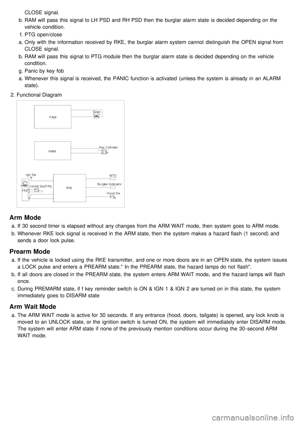
2. Functional Diagram
Arm Mode
a.If 30 second timer is elapsed without any changes from the ARM WAIT mode, then system goes to ARM mode.
b. Whenever RKE lock signal is received in the ARM state, then the system makes a hazard flash (1 second) and
sends a door lock pulse.
Prearm Mode
a.If the vehicle is locked using the RKE transmitter, and one or more doors are in an OPEN state, the system issues
a LOCK pulse and enters a PREARM state." In the PREARM state, the hazard lamps do not flash".
b. If all doors are closed in the PREARM state, the system enters ARM WAIT mode, and the hazard lamps will flash
once.
c. During PREMARM state, if f key reminder switch is ON & IGN 1 & IGN 2 are turned on in this state, the system
immediately goes to DISARM state
Arm Wait Mode
a.The ARM WAIT mode is active for 30 seconds. If any entrance (hood, doors, tailgate) is opened, any lock knob is
moved to an UNLOCK state, or the ignition switch is turned ON, the system will immediately enter DISARM mode.
The system will enter ARM state if none of the previously mention conditions occur during the 30- second ARM
WAIT mode.
Page 1258 of 1575
2007 > 2.7L V6 GASOLINE >
CIRCUIT DIAGRAM
Page 1332 of 1575
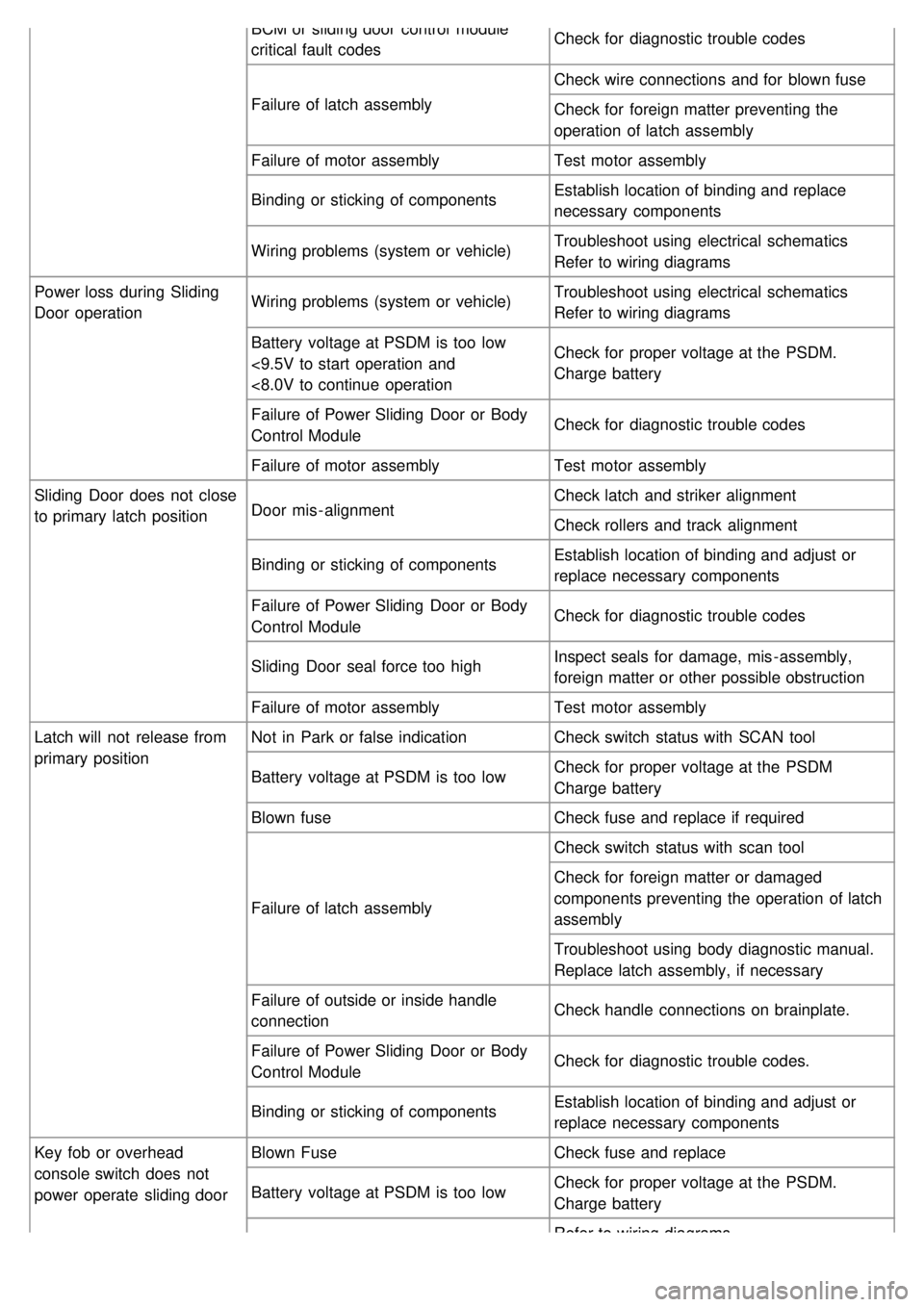
BCM or sliding door control module
critical fault codesCheck for diagnostic trouble codes
Failure of latch assembly Check wire connections and for blown fuse
Check for foreign matter preventing the
operation of latch assembly
Failure of motor assembly Test motor assembly
Binding or sticking of components Establish location of binding and replace
necessary components
Wiring problems (system or vehicle) Troubleshoot using electrical schematics
Refer to wiring diagrams
Power loss during Sliding
Door operation Wiring problems (system or vehicle)
Troubleshoot using electrical schematics
Refer to wiring diagrams
Battery voltage at PSDM is too low
<9.5V to start operation and
<8.0V to continue operation Check for proper voltage at the PSDM.
Charge battery
Failure of Power Sliding Door or Body
Control Module Check for diagnostic trouble codes
Failure of motor assembly Test motor assembly
Sliding Door does not close
to primary latch position Door mis - alignment Check latch and striker alignment
Check rollers and track alignment
Binding or sticking of components Establish location of binding and adjust or
replace necessary components
Failure of Power Sliding Door or Body
Control Module Check for diagnostic trouble codes
Sliding Door seal force too high Inspect seals for damage, mis - assembly,
foreign matter or other possible obstruction
Failure of motor assembly Test motor assembly
Latch will not release from
primary position Not in Park or false indication
Check switch status with SCAN tool
Battery voltage at PSDM is too low Check for proper voltage at the PSDM
Charge battery
Blown fuse Check fuse and replace if required
Failure of latch assembly Check switch status with scan tool
Check for foreign matter or damaged
components preventing the operation of latch
assembly
Troubleshoot using body diagnostic manual.
Replace latch assembly, if necessary
Failure of outside or inside handle
connection Check handle connections on brainplate.
Failure of Power Sliding Door or Body
Control Module Check for diagnostic trouble codes.
Binding or sticking of components Establish location of binding and adjust or
replace necessary components
Key fob or overhead
console switch does not
power operate sliding door Blown Fuse
Check fuse and replace
Battery voltage at PSDM is too low Check for proper voltage at the PSDM.
Charge battery
Refer to wiring diagrams