Page 1023 of 1575
2007 > 2.7L V6 GASOLINE >
REPLACEMENT
FRONT DOOR TRIM REPLACEMENT
a. Take care not to scratch the door trim and other parts.
b. Put on gloves to protect your hands.
1. Remove the quadrant inner cover (A).
2.Loosen the mounting screw, remove the inside handle cover (A).
3.Loosen the door trim (C) mounting screws. Release the clips that hold the door trim, then remove the door trim by
pulling it upward. Disconnect the power window switch connector (A), power mirror connector (B), and door
courtesy lamp connector (D).
[LHD]
Page 1050 of 1575
Page 1052 of 1575
2007 > 2.7L V6 GASOLINE >
REPLACEMENT
OUTSIDE REAR VIEW MIRROR RELPLACEMENT
a. When prying with a flat- tipper screwdriver, wrap it with protective tape, and apply protective tape around the
related parts, to prevent damage.
b. Put on gloves to protect your hands.
1. Remove the quadrant inner cover (A).
2.Remove the door trim.
3. After disconnecting the connector (A), remove the outside rear view mirror (B).
4.Installation is the reverse of removal.
INSIDE REAR VIEW MIRROR REPLACEMENT
1.Push the inside rear view mirror base (A) down to remove to inside rear view mirror assembly (B).
Page 1053 of 1575
2.Installation is the reverse of removal.
ECM MIRROR REPLACEMENT
1.Remove the ECM mirror cover (A).
2.Remove the cover and connector (A).
3. Push the ECM mirror base down to remove the ECM mirror assembly (B).
4.Installation is the reverse of removal.
Page 1100 of 1575

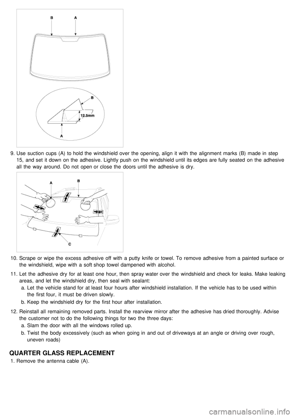
9.Use suction cups (A) to hold the windshield over the opening, align it with the alignment marks (B) made in step
15, and set it down on the adhesive. Lightly push on the windshield until its edges are fully seated on the adhesive
all the way around. Do not open or close the doors until the adhesive is dry.
10. Scrape or wipe the excess adhesive off with a putty knife or towel. To remove adhesive from a painted surface or
the windshield, wipe with a soft shop towel dampened with alcohol.
11. Let the adhesive dry for at least one hour, then spray water over the windshield and check for leaks. Make leaking
areas, and let the windshield dry, then seal with sealant:
a. Let the vehicle stand for at least four hours after windshield installation. If the vehicle has to be used within
the first four, it must be driven slowly.
b. Keep the windshield dry for the first hour after installation.
12. Reinstall all remaining removed parts. Install the rearview mirror after the adhesive has dried thoroughly. Advise
the customer not to do the following things for two the three days:
a. Slam the door with all the windows rolled up.
b. Twist the body excessively (such as when going in and out of driveways at an angle or driving over rough,
uneven roads)
QUARTER GLASS REPLACEMENT
1.Remove the antenna cable (A).
Page 1223 of 1575

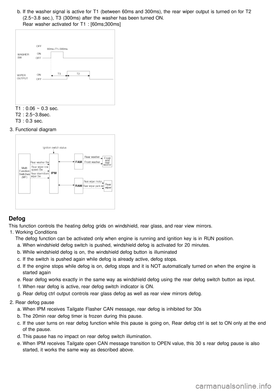
b.If the washer signal is active for T1 (between 60ms and 300ms), the rear wiper output is turned on for T2
(2.5~3.8 sec.), T3 (300ms) after the washer has been turned ON.
Rear washer activated for T1 : [60ms;300ms]
T1 : 0.06 ~ 0.3 sec.
T2 : 2.5~3.8sec.
T3 : 0.3 sec.
3. Functional diagram
Defog
This function controls the heating defog grids on windshield, rear glass, and rear view mirrors.
1. Working Conditions
The defog function can be activated only when engine is running and ignition key is in RUN position.
a. When windshield defog switch is pushed, windshield defog is activated for 20 minutes.
b. While windshield defog is on, the windshield defog button is illuminated
c. If the switch is pushed again while defog is already active, defog stops.
d. If the engine stops while defog is on, defog stops and it is NOT automatically turned on when the engine is
started again
e. Rear defog works exactly in the same way as windshield defog using the rear defog switch button as input.
f. When rear defog is active, rear defog switch indicator is ON.
g. Rear defog ctrl output controls rear glass defog as well as rear view mirrors defog.
2. Rear defog pause
a. When IPM receives Tailgate Flasher CAN message, rear defog is inhibited for 30s
b. The 20min rear defog timer is frozen during this pause.
c. If the user turns on rear defog function while this pause is going on, Rear defog ctrl is set to ON only at the end
of the pause.
d. This pause has no impact on rear defog switch illumination.
e. When IPM receives Tailgate open CAN message transition to OPEN value, this 30 s rear defog pause is also
started, it works the same way as described above.
Page 1225 of 1575

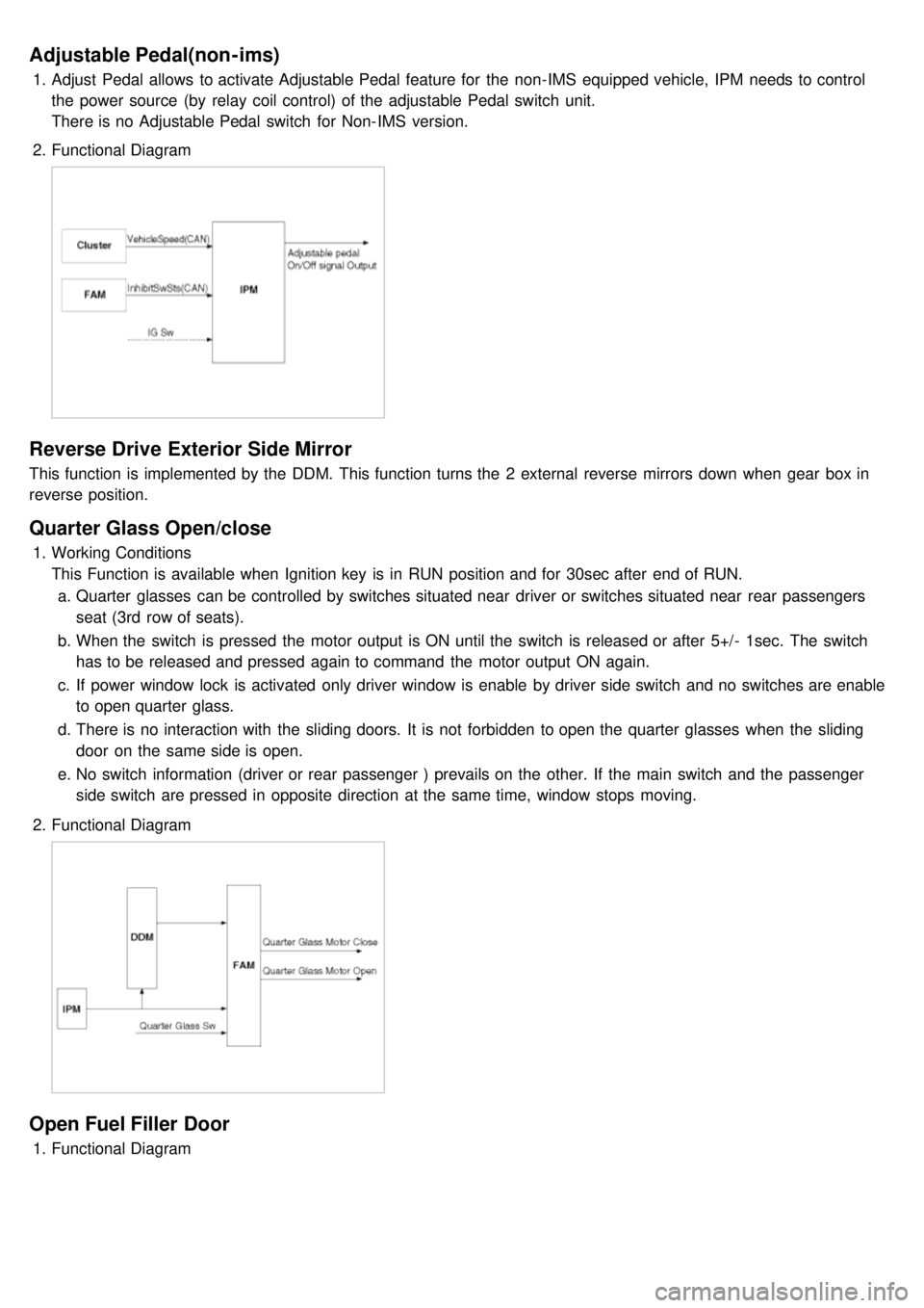
Adjustable Pedal(non-ims)
1.Adjust Pedal allows to activate Adjustable Pedal feature for the non- IMS equipped vehicle, IPM needs to control
the power source (by relay coil control) of the adjustable Pedal switch unit.
There is no Adjustable Pedal switch for Non- IMS version.
2. Functional Diagram
Reverse Drive Exterior Side Mirror
This function is implemented by the DDM. This function turns the 2 external reverse mirrors down when gear box in
reverse position.
Quarter Glass Open/close
1.Working Conditions
This Function is available when Ignition key is in RUN position and for 30sec after end of RUN.
a. Quarter glasses can be controlled by switches situated near driver or switches situated near rear passengers
seat (3rd row of seats).
b. When the switch is pressed the motor output is ON until the switch is released or after 5+/- 1sec. The switch
has to be released and pressed again to command the motor output ON again.
c. If power window lock is activated only driver window is enable by driver side switch and no switches are enable
to open quarter glass.
d. There is no interaction with the sliding doors. It is not forbidden to open the quarter glasses when the sliding
door on the same side is open.
e. No switch information (driver or rear passenger ) prevails on the other. If the main switch and the passenger
side switch are pressed in opposite direction at the same time, window stops moving.
2. Functional Diagram
Open Fuel Filler Door
1.Functional Diagram
Page 1259 of 1575

2007 > 2.7L V6 GASOLINE >
DESCRIPTION
An optimal seat position set by a driver can be memorized in P/seat unit by memory SW and position SW, which
enables restoration of seat position set by the driver despite seat adjustments.
Furthermore, data is transmitted between P/seat and IPM, DDM, ADM, RAM, FAM, CLUSTER through CAN BUS.
Seat position presets cannot be recalled while driving. An emergency stop function is provided; additional functions are
described below.
1. It conducts manual operation of seat by CAN BUS data transmitted by DDM as well as that of adjustable pedal by
CAN BUS data transmitted by IPM received when operating SW manually.
2. Manual SW behavior when communication stops (back- up behavior)
a. Slide front/rear
b. Recline front/rear
c. Position control of slide motor is possible by manual SW even in case of congestion in CPU or removal of a
fuse for P/seat unit B.
3. 2 memory locations are provided for storing seat, outside mirror, and adjustable pedal presets.
4. The driver seat can be set to slide rearward when the ignition key is removed, and forward when the key is
inserted.
5. 2 additional presets for seat, mirror, and adjustable pedal position can be stored with the RKE transmitter.
OPERATION
MANUAL OPERATION
Manual operation of the driver seat and adjustable pedals is possible provided the transaxle is in 'P' range and the
vehicle speed is 0 MPH. Operation of the manual controls overrides any automatic operation commanded via CAN.
MEMORY OPERATION
1. Pressing the 'M' button on the control panel will place the system into memory storage mode and will result in a
single pulse from the output buzzer.
2. If one of the memory location buttons is pressed and held within 5 seconds of pressing the 'M' button, the output
buzzer will pulse twice to indicate successful storage of seat, mirror, and adjustable pedal positions.
3. The ignition switch must be in the RUN or START position, the vehicle speed must be 0 MPH, and the transaxle
must be in 'P' range to store memory presets.
4. Pressing the 'M' button while recalling a stored preset will halt the preset recall operation.
5. Memory will be cleared if battery is removed.
MEMORY REPLAY OPERATION
1.Pressing one of the memory location buttons will result in the driver seat, outside mirrors, and adjustable pedals
being positioned based on the stored preset data.
2. The ignition switch must be in the RUN position, the transaxle must be in 'P' range, the vehicle speed must be 0
MPH, and the manual functions must not be in operation to recall stored presets.
3. Others
a. Play operation not recorded in the position switch will not be conducted and there will be no buzzer output.
b. If other data is received during preset recall operation, the most recent preset recall signal will take
precedence.
c. If engine is started during preset recall operation, halt preset recall operation, and resume it toward target
position 100ms after Ignition switch is returned to "RUN". However, if the START state lasts over 5 sec., it will
not resume even after returning to RUN.
d. If preset recall order is received during engine start, preset recall operation is inhibited.
e. If input from manual switch for seat and adjust pedal occurs during preset recall operation of seat and adjust
pedal, halt all their preset recall operations.
f. If an error occurs during manual operation of seat and adjust pedal, delete Memory.