2007 KIA CARNIVAL window
[x] Cancel search: windowPage 1242 of 1575
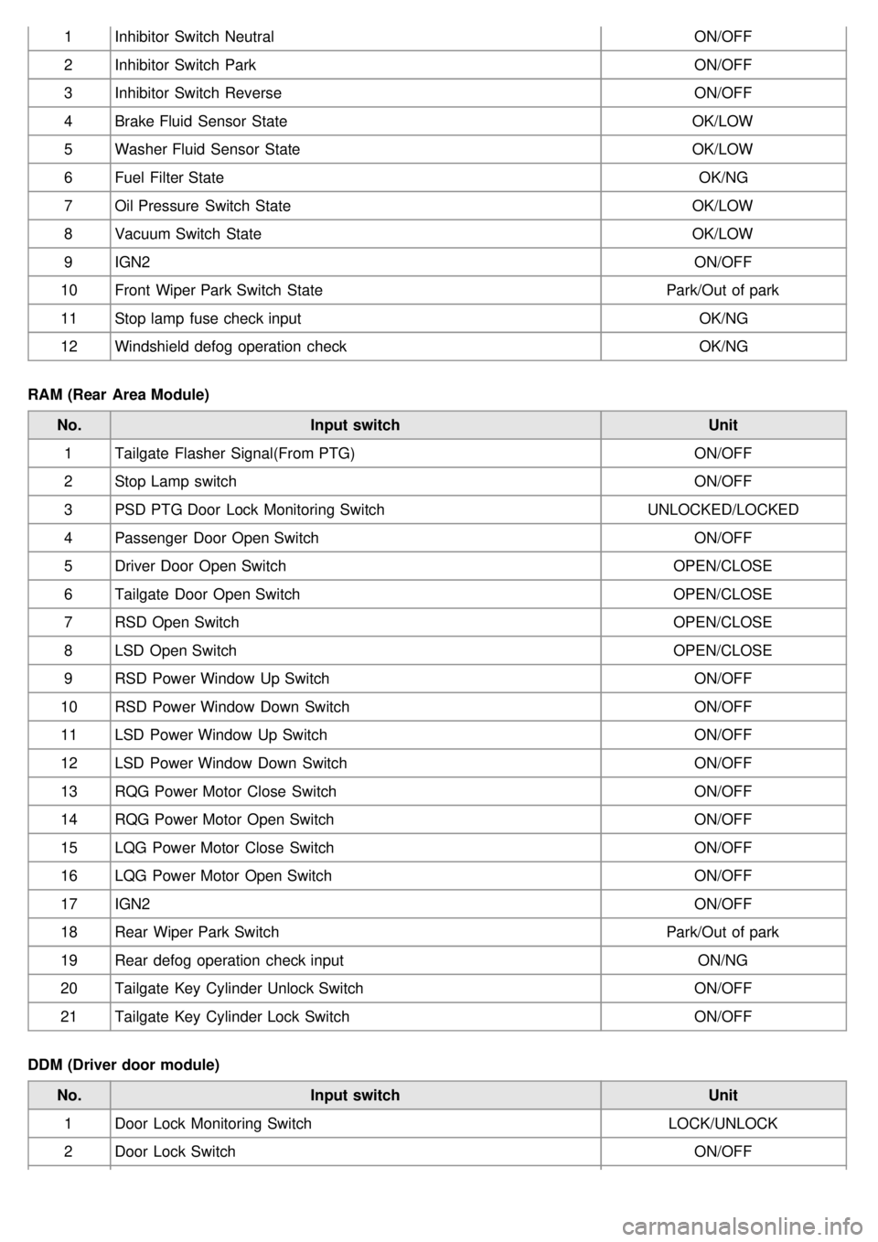
1Inhibitor Switch Neutral ON/OFF
2 Inhibitor Switch Park ON/OFF
3 Inhibitor Switch Reverse ON/OFF
4 Brake Fluid Sensor State OK/LOW
5 Washer Fluid Sensor State OK/LOW
6 Fuel Filter State OK/NG
7 Oil Pressure Switch State OK/LOW
8 Vacuum Switch State OK/LOW
9 IGN2 ON/OFF
10 Front Wiper Park Switch State Park/Out of park
11 Stop lamp fuse check input OK/NG
12 Windshield defog operation check OK/NG
RAM (Rear Area Module) No. Input switch Unit
1 Tailgate Flasher Signal(From PTG) ON/OFF
2 Stop Lamp switch ON/OFF
3 PSD PTG Door Lock Monitoring Switch UNLOCKED/LOCKED
4 Passenger Door Open Switch ON/OFF
5 Driver Door Open Switch OPEN/CLOSE
6 Tailgate Door Open Switch OPEN/CLOSE
7 RSD Open Switch OPEN/CLOSE
8 LSD Open Switch OPEN/CLOSE
9 RSD Power Window Up Switch ON/OFF
10 RSD Power Window Down Switch ON/OFF
11 LSD Power Window Up Switch ON/OFF
12 LSD Power Window Down Switch ON/OFF
13 RQG Power Motor Close Switch ON/OFF
14 RQG Power Motor Open Switch ON/OFF
15 LQG Power Motor Close Switch ON/OFF
16 LQG Power Motor Open Switch ON/OFF
17 IGN2 ON/OFF
18 Rear Wiper Park Switch Park/Out of park
19 Rear defog operation check input ON/NG
20 Tailgate Key Cylinder Unlock Switch ON/OFF
21 Tailgate Key Cylinder Lock Switch ON/OFF
DDM (Driver door module) No. Input switch Unit
1 Door Lock Monitoring Switch LOCK/UNLOCK
2 Door Lock Switch ON/OFF
Page 1243 of 1575
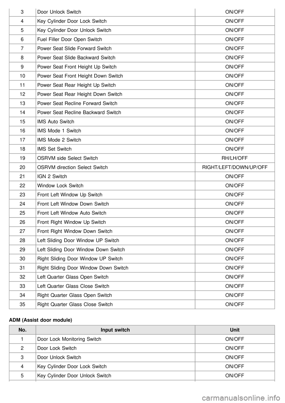
3Door Unlock Switch ON/OFF
4 Key Cylinder Door Lock Switch ON/OFF
5 Key Cylinder Door Unlock Switch ON/OFF
6 Fuel Filler Door Open Switch ON/OFF
7 Power Seat Slide Forward Switch ON/OFF
8 Power Seat Slide Backward Switch ON/OFF
9 Power Seat Front Height Up Switch ON/OFF
10 Power Seat Front Height Down Switch ON/OFF
11 Power Seat Rear Height Up Switch ON/OFF
12 Power Seat Rear Height Down Switch ON/OFF
13 Power Seat Recline Forward Switch ON/OFF
14 Power Seat Recline Backward Switch ON/OFF
15 IMS Auto Switch ON/OFF
16 IMS Mode 1 Switch ON/OFF
17 IMS Mode 2 Switch ON/OFF
18 IMS Set Switch ON/OFF
19 OSRVM side Select Switch RH/LH/OFF
20 OSRVM direction Select Switch RIGHT/LEFT/DOWN/UP/OFF
21 IGN 2 Switch ON/OFF
22 Window Lock Switch ON/OFF
23 Front Left Window Up Switch ON/OFF
24 Front Left Window Down Switch ON/OFF
25 Front Left Window Auto Switch ON/OFF
26 Front Right Window Up Switch ON/OFF
27 Front Right Window Down Switch ON/OFF
28 Left Sliding Door Window UP Switch ON/OFF
29 Left Sliding Door Window Down Switch ON/OFF
30 Right Sliding Door Window UP Switch ON/OFF
31 Right Sliding Door Window Down Switch ON/OFF
32 Left Quarter Glass Open Switch ON/OFF
33 Left Quarter Glass Close Switch ON/OFF
34 Right Quarter Glass Open Switch ON/OFF
35 Right Quarter Glass Close Switch ON/OFF
ADM (Assist door module) No. Input switch Unit
1 Door Lock Monitoring Switch ON/OFF
2 Door Lock Switch ON/OFF
3 Door Unlock Switch ON/OFF
4 Key Cylinder Door Lock Switch ON/OFF
5 Key Cylinder Door Unlock Switch ON/OFF
Page 1244 of 1575
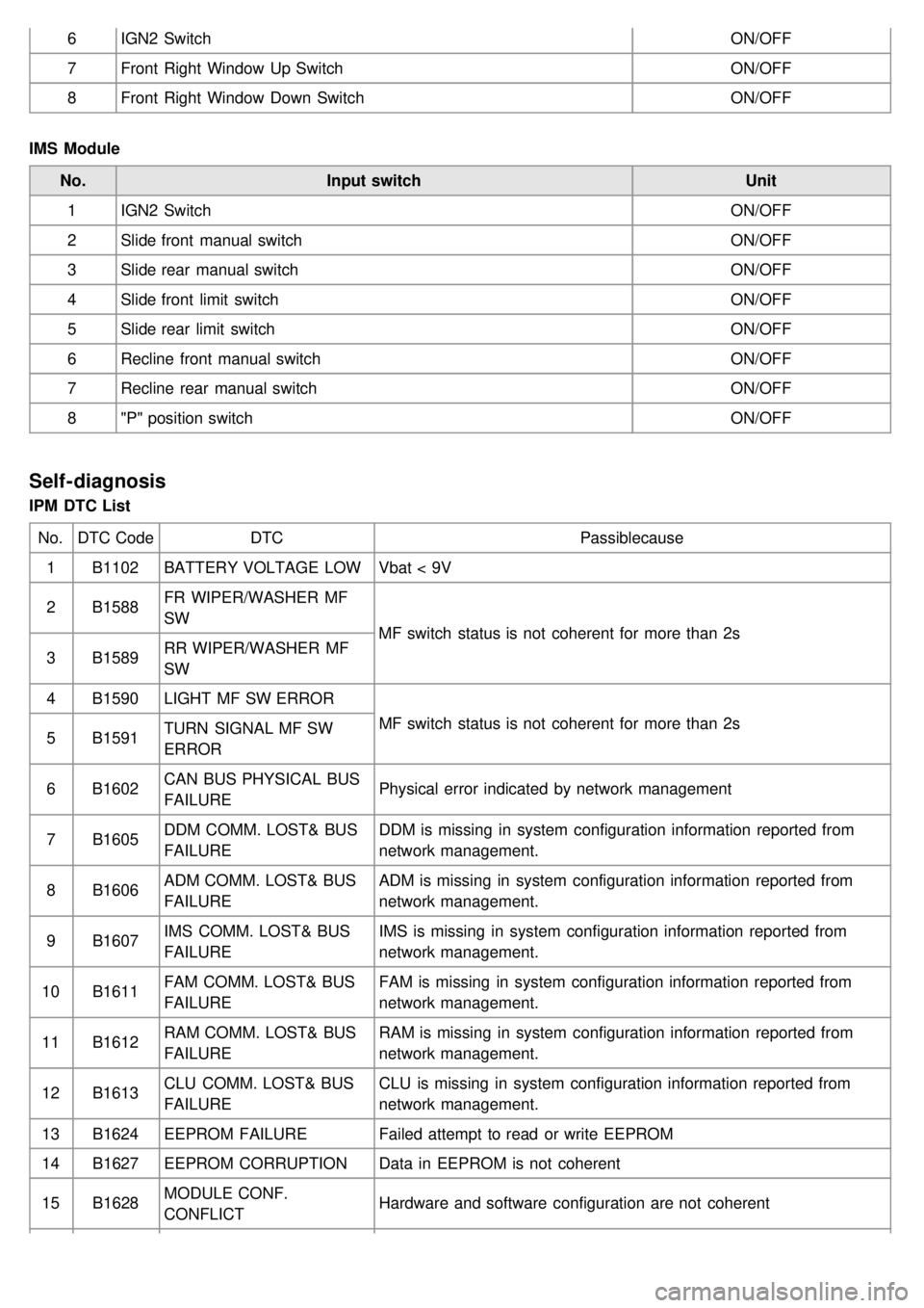
6IGN2 Switch ON/OFF
7 Front Right Window Up Switch ON/OFF
8 Front Right Window Down Switch ON/OFF
IMS Module No. Input switch Unit
1 IGN2 Switch ON/OFF
2 Slide front manual switch ON/OFF
3 Slide rear manual switch ON/OFF
4 Slide front limit switch ON/OFF
5 Slide rear limit switch ON/OFF
6 Recline front manual switch ON/OFF
7 Recline rear manual switch ON/OFF
8 "P" position switch ON/OFF
Self-diagnosis
IPM DTC List
No. DTC Code DTC Passiblecause
1 B1102 BATTERY VOLTAGE LOW Vbat < 9V
2 B1588 FR WIPER/WASHER MF
SW
MF switch status is not coherent for more than 2s
3 B1589 RR WIPER/WASHER MF
SW
4 B1590 LIGHT MF SW ERROR
MF switch status is not coherent for more than 2s
5 B1591 TURN SIGNAL MF SW
ERROR
6 B1602 CAN BUS PHYSICAL BUS
FAILURE Physical error indicated by network management
7 B1605 DDM COMM. LOST& BUS
FAILURE DDM is missing in system configuration information reported from
network management.
8 B1606 ADM COMM. LOST& BUS
FAILURE ADM is missing in system configuration information reported from
network management.
9 B1607 IMS COMM. LOST& BUS
FAILURE IMS is missing in system configuration information reported from
network management.
10 B1611 FAM COMM. LOST& BUS
FAILURE FAM is missing in system configuration information reported from
network management.
11 B1612 RAM COMM. LOST& BUS
FAILURE RAM is missing in system configuration information reported from
network management.
12 B1613 CLU COMM. LOST& BUS
FAILURE CLU is missing in system configuration information reported from
network management.
13 B1624 EEPROM FAILURE Failed attempt to read or write EEPROM
14 B1627 EEPROM CORRUPTION Data in EEPROM is not coherent
15 B1628 MODULE CONF.
CONFLICT Hardware and software configuration are not coherent
Page 1247 of 1575
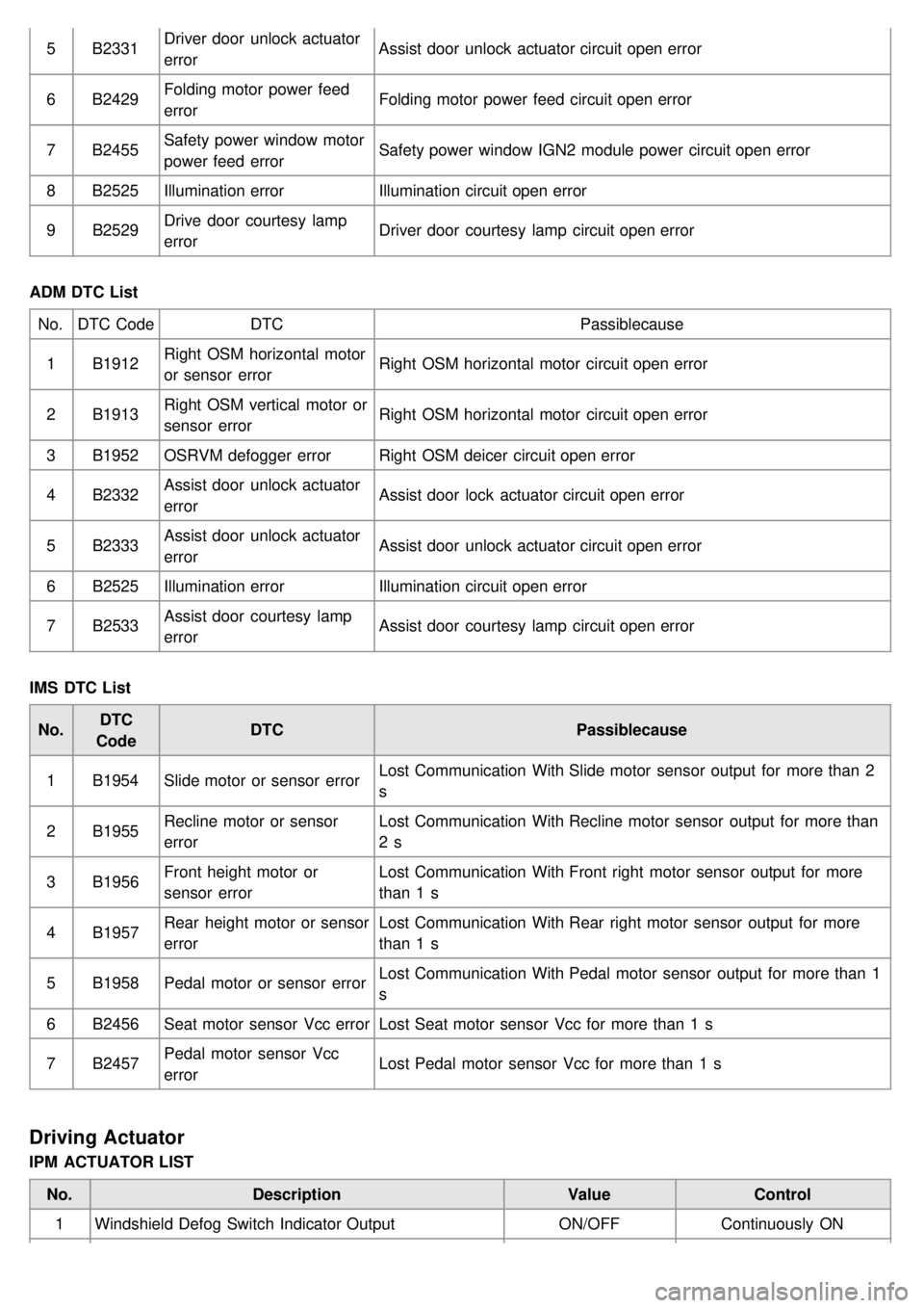
5B2331 Driver door unlock actuator
error Assist door unlock actuator circuit open error
6 B2429 Folding motor power feed
error Folding motor power feed circuit open error
7 B2455 Safety power window motor
power feed error Safety power window IGN2 module power circuit open error
8 B2525 Illumination error Illumination circuit open error
9 B2529 Drive door courtesy lamp
error Driver door courtesy lamp circuit open error
ADM DTC List No. DTC Code DTC Passiblecause
1 B1912 Right OSM horizontal motor
or sensor error Right OSM horizontal motor circuit open error
2 B1913 Right OSM vertical motor or
sensor error Right OSM horizontal motor circuit open error
3 B1952 OSRVM defogger error Right OSM deicer circuit open error
4 B2332 Assist door unlock actuator
error Assist door lock actuator circuit open error
5 B2333 Assist door unlock actuator
error Assist door unlock actuator circuit open error
6 B2525 Illumination error Illumination circuit open error
7 B2533 Assist door courtesy lamp
error Assist door courtesy lamp circuit open error
IMS DTC List No. DTC
Code DTC
Passiblecause
1 B1954 Slide motor or sensor error Lost Communication With Slide motor sensor output for more than 2
s
2 B1955 Recline motor or sensor
error Lost Communication With Recline motor sensor output for more than
2 s
3 B1956 Front height motor or
sensor error Lost Communication With Front right motor sensor output for more
than 1 s
4 B1957 Rear height motor or sensor
error Lost Communication With Rear right motor sensor output for more
than 1 s
5 B1958 Pedal motor or sensor error Lost Communication With Pedal motor sensor output for more than 1
s
6 B2456 Seat motor sensor Vcc error Lost Seat motor sensor Vcc for more than 1 s
7 B2457 Pedal motor sensor Vcc
error Lost Pedal motor sensor Vcc for more than 1 s
Driving Actuator
IPM ACTUATOR LIST
No. Description ValueControl
1 Windshield Defog Switch Indicator Output ON/OFFContinuously ON
Page 1249 of 1575
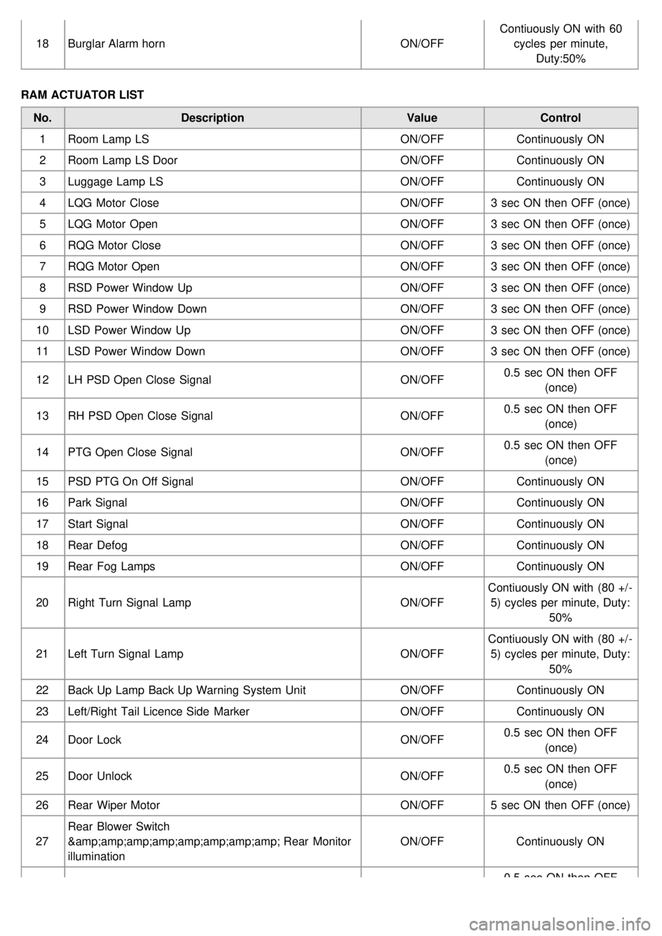
18Burglar Alarm horn ON/OFFContiuously ON with 60
cycles per minute, Duty:50%
RAM ACTUATOR LIST No. Description ValueControl
1 Room Lamp LS ON/OFFContinuously ON
2 Room Lamp LS Door ON/OFFContinuously ON
3 Luggage Lamp LS ON/OFFContinuously ON
4 LQG Motor Close ON/OFF3 sec ON then OFF (once)
5 LQG Motor Open ON/OFF3 sec ON then OFF (once)
6 RQG Motor Close ON/OFF3 sec ON then OFF (once)
7 RQG Motor Open ON/OFF3 sec ON then OFF (once)
8 RSD Power Window Up ON/OFF3 sec ON then OFF (once)
9 RSD Power Window Down ON/OFF3 sec ON then OFF (once)
10 LSD Power Window Up ON/OFF3 sec ON then OFF (once)
11 LSD Power Window Down ON/OFF3 sec ON then OFF (once)
12 LH PSD Open Close Signal ON/OFF0.5 sec ON then OFF
(once)
13 RH PSD Open Close Signal ON/OFF0.5 sec ON then OFF
(once)
14 PTG Open Close Signal ON/OFF0.5 sec ON then OFF
(once)
15 PSD PTG On Off Signal ON/OFFContinuously ON
16 Park Signal ON/OFFContinuously ON
17 Start Signal ON/OFFContinuously ON
18 Rear Defog ON/OFFContinuously ON
19 Rear Fog Lamps ON/OFFContinuously ON
20 Right Turn Signal Lamp ON/OFFContiuously ON with (80 +/ -
5) cycles per minute, Duty: 50%
21 Left Turn Signal Lamp ON/OFFContiuously ON with (80 +/ -
5) cycles per minute, Duty: 50%
22 Back Up Lamp Back Up Warning System Unit ON/OFFContinuously ON
23 Left/Right Tail Licence Side Marker ON/OFFContinuously ON
24 Door Lock ON/OFF0.5 sec ON then OFF
(once)
25 Door Unlock ON/OFF0.5 sec ON then OFF
(once)
26 Rear Wiper Motor ON/OFF5 sec ON then OFF (once)
27 Rear Blower Switch
&amp;amp;amp;amp;amp;amp; Rear Monitor
illumination ON/OFF
Continuously ON
0.5 sec ON then OFF
Page 1250 of 1575
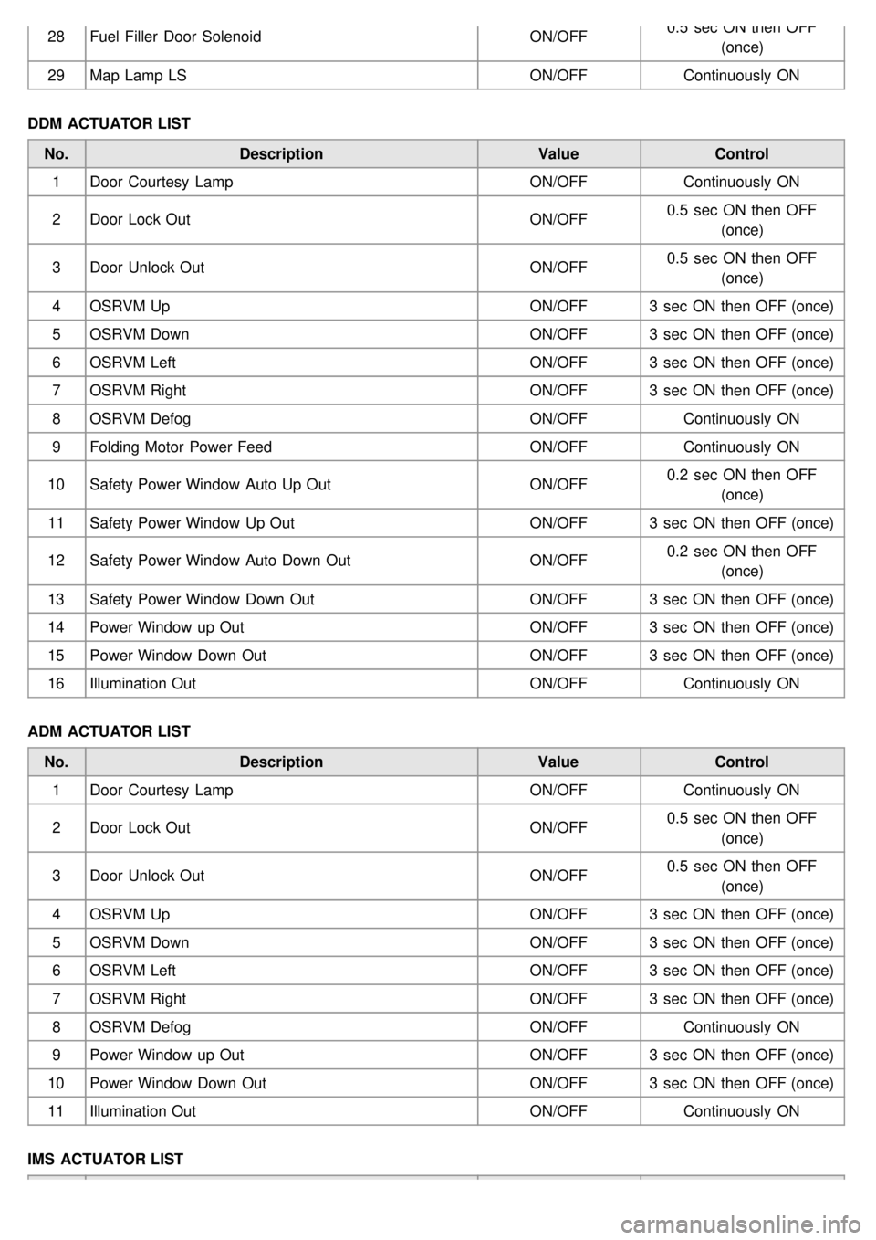
28Fuel Filler Door Solenoid ON/OFF0.5 sec ON then OFF
(once)
29 Map Lamp LS ON/OFFContinuously ON
DDM ACTUATOR LIST No. Description ValueControl
1 Door Courtesy Lamp ON/OFFContinuously ON
2 Door Lock Out ON/OFF0.5 sec ON then OFF
(once)
3 Door Unlock Out ON/OFF0.5 sec ON then OFF
(once)
4 OSRVM Up ON/OFF3 sec ON then OFF (once)
5 OSRVM Down ON/OFF3 sec ON then OFF (once)
6 OSRVM Left ON/OFF3 sec ON then OFF (once)
7 OSRVM Right ON/OFF3 sec ON then OFF (once)
8 OSRVM Defog ON/OFFContinuously ON
9 Folding Motor Power Feed ON/OFFContinuously ON
10 Safety Power Window Auto Up Out ON/OFF0.2 sec ON then OFF
(once)
11 Safety Power Window Up Out ON/OFF3 sec ON then OFF (once)
12 Safety Power Window Auto Down Out ON/OFF0.2 sec ON then OFF
(once)
13 Safety Power Window Down Out ON/OFF3 sec ON then OFF (once)
14 Power Window up Out ON/OFF3 sec ON then OFF (once)
15 Power Window Down Out ON/OFF3 sec ON then OFF (once)
16 Illumination Out ON/OFFContinuously ON
ADM ACTUATOR LIST No. Description ValueControl
1 Door Courtesy Lamp ON/OFFContinuously ON
2 Door Lock Out ON/OFF0.5 sec ON then OFF
(once)
3 Door Unlock Out ON/OFF0.5 sec ON then OFF
(once)
4 OSRVM Up ON/OFF3 sec ON then OFF (once)
5 OSRVM Down ON/OFF3 sec ON then OFF (once)
6 OSRVM Left ON/OFF3 sec ON then OFF (once)
7 OSRVM Right ON/OFF3 sec ON then OFF (once)
8 OSRVM Defog ON/OFFContinuously ON
9 Power Window up Out ON/OFF3 sec ON then OFF (once)
10 Power Window Down Out ON/OFF3 sec ON then OFF (once)
11 Illumination Out ON/OFFContinuously ON
IMS ACTUATOR LIST
Page 1326 of 1575
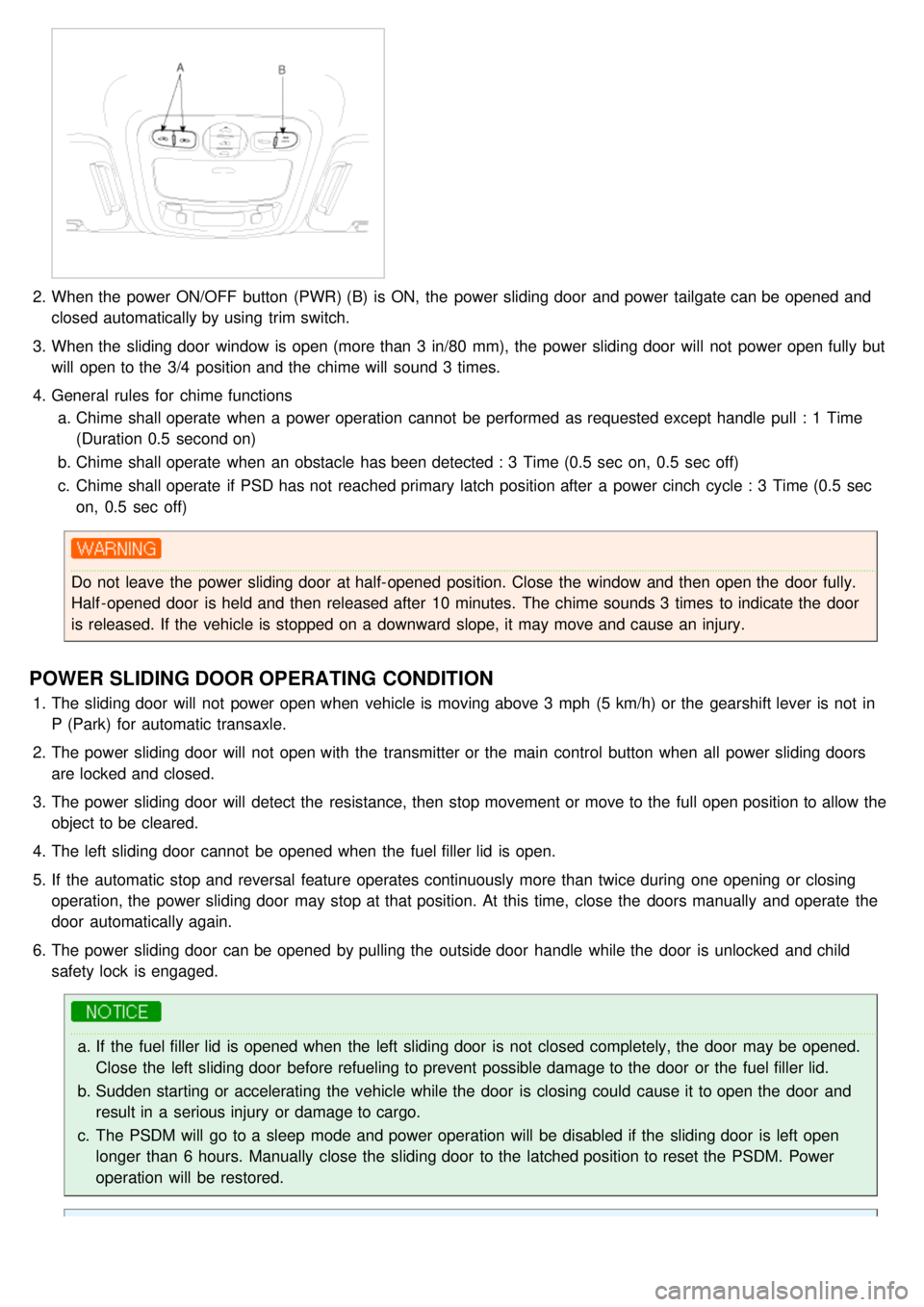
2.When the power ON/OFF button (PWR) (B) is ON, the power sliding door and power tailgate can be opened and
closed automatically by using trim switch.
3. When the sliding door window is open (more than 3 in/80 mm), the power sliding door will not power open fully but
will open to the 3/4 position and the chime will sound 3 times.
4. General rules for chime functions
a. Chime shall operate when a power operation cannot be performed as requested except handle pull : 1 Time
(Duration 0.5 second on)
b. Chime shall operate when an obstacle has been detected : 3 Time (0.5 sec on, 0.5 sec off)
c. Chime shall operate if PSD has not reached primary latch position after a power cinch cycle : 3 Time (0.5 sec
on, 0.5 sec off)
Do not leave the power sliding door at half- opened position. Close the window and then open the door fully.
Half - opened door is held and then released after 10 minutes. The chime sounds 3 times to indicate the door
is released. If the vehicle is stopped on a downward slope, it may move and cause an injury.
POWER SLIDING DOOR OPERATING CONDITION
1.The sliding door will not power open when vehicle is moving above 3 mph (5 km/h) or the gearshift lever is not in
P (Park) for automatic transaxle.
2. The power sliding door will not open with the transmitter or the main control button when all power sliding doors
are locked and closed.
3. The power sliding door will detect the resistance, then stop movement or move to the full open position to allow the
object to be cleared.
4. The left sliding door cannot be opened when the fuel filler lid is open.
5. If the automatic stop and reversal feature operates continuously more than twice during one opening or closing
operation, the power sliding door may stop at that position. At this time, close the doors manually and operate the
door automatically again.
6. The power sliding door can be opened by pulling the outside door handle while the door is unlocked and child
safety lock is engaged.
a.If the fuel filler lid is opened when the left sliding door is not closed completely, the door may be opened.
Close the left sliding door before refueling to prevent possible damage to the door or the fuel filler lid.
b. Sudden starting or accelerating the vehicle while the door is closing could cause it to open the door and
result in a serious injury or damage to cargo.
c. The PSDM will go to a sleep mode and power operation will be disabled if the sliding door is left open
longer than 6 hours. Manually close the sliding door to the latched position to reset the PSDM. Power
operation will be restored.
Page 1364 of 1575
2007 > 2.7L V6 GASOLINE >
REPLACEMENT
1.Disconnect the negative ( - ) battery terminal.
2. Remove the front door trim panel. (Refer to the Body group - front door)
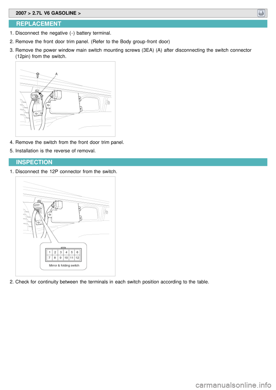
3. Remove the power window main switch mounting screws (3EA) (A) after disconnecting the switch connector
(12pin) from the switch.
4.Remove the switch from the front door trim panel.
5. Installation is the reverse of removal.
INSPECTION
1.Disconnect the 12P connector from the switch.
2.Check for continuity between the terminals in each switch position according to the table.