2007 KIA CARNIVAL alarm
[x] Cancel search: alarmPage 1199 of 1575

Keyless Entry And
Burglar Alarm
Page 1200 of 1575

2007 > 2.7L V6 GASOLINE >
DESCRIPTION
KEYLESS ENTRY SYSTEM
The keyless entry system uses a handheld transmitter and IPM - mounted receiver to control door locks, alarm
functions, Power Tail Gate (PTG) and Power Sliding Doors (PSD).
The receiver of the keyless entry system are built- in the IPM(In - Panel Module).
Page 1211 of 1575
2007 > 2.7L V6 GASOLINE >
DESCRIPTION
All modules are linked a low speed CAN network.
The input information for the modules is coming from both the CAN network and the hardware components
(actuatorsand sensors).
a. FAM (Front Area Module)
a. Headlamp low/high beam control (with DRL)
b. Park lamp control
c. Front fog lamp control
d. Front turn signal lamp control
e. Windshield wiper control
f. Windshield deicer
g. Diagnostics
b. IPM (In - Panel Module)
a. RKE (Remote Keyless Control)
b. VAS (Voice Alarm System)
c. Ignition key hole illumination
d. Switch indicators control
e. Panel light control
f. Seat belt warning
g. Auto light/DRL control (Logic)
h. Windshield/Rear wiper control (Logic)
i. Turn and Hazard lamp control (Logic)
j. Central door lock (Logic)
k. Windshield deicer timer
l. Rear glass defog timer
m. Gateway for ISO- 9141 (K- Line)
c. RAM (Rear Area Module)
a. Tail lamp control
b. Turn and Hazard lamp control
c. Back up lamp control
d. Rea fog lamp control
e. Stop lamp outage detection
f. Sliding door power window/Quarter glass control
g. Room lamp control
h. Rear wiper control
i. Rear glass defog
j. Fuel filler door open solenoid control
d. ADM (Assist Drive Module)
e. DDM (Driver Drive Module)
MODULE INTRODUCTION
FAM/IPM/RAM consists of a power board and an electronic board. The power board contains circuit protection devices
and switching devices. The electronic board uses Intelligent Power Switching (IPS) for HS/LS load control, logic
functions and CAN/K- Line communication. The power board and electronic board are connected with pin blocks for
the Front Area Module (FAM) and VCD (Variable Connection Displacement) for the In- Panel Module (IPM) and the
Rear Area Module (RAM).
Page 1214 of 1575
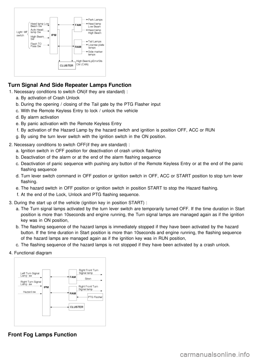
Turn Signal And Side Repeater Lamps Function
1.Necessary conditions to switch ON(if they are standard) :
a. By activation of Crash Unlock
b. During the opening / closing of the Tail gate by the PTG Flasher input
c. With the Remote Keyless Entry to lock / unlock the vehicle
d. By alarm activation
e. By panic activation with the Remote Keyless Entry
f. By activation of the Hazard Lamp by the hazard switch and ignition is position OFF, ACC or RUN
g. By using the turn lever switch with the ignition switch in the ON position.
2. Necessary conditions to switch OFF(if they are standard) :
a. Ignition switch in OFF position for deactivation of crash unlock flashing
b. Deactivation of the alarm or at the end of the alarm flashing sequence
c. Deactivation of panic sequence with pushing any button of the Remote Keyless Entry or at the end of the panic
flashing sequence
d. Turn lever switch command in OFF postion or ignition switch in OFF, ACC or START position to stop turn lever
flashing.
e. The hazard switch in OFF position or ignition switch in position START to stop the Hazard flashing.
f. At the end of the Lock, Unlock and PTG flashing sequence.
3. During the start up of the vehicle (ignition key in position START) :
a. The Turn signal lamps activated by the turn lever switch are temporarily turned OFF. If the time duration in Start
position is more than 10seconds and engine running, the Turn signal lamps are managed again as if the ignition
key was in ON position,
b. The flashing sequence of the hazard lamps is immediately stopped if they have been activated by the hazard
button. If the time duration in Start position is more than 10seconds and engine running, the flashing sequence
of the hazard lamps are managed again as if the ignition key was in RUN position,
c. The flashing sequence of the hazard lamps is not stopped if they have been activated by a crash unlock.
4. Functional diagram
Front Fog Lamps Function
Page 1221 of 1575
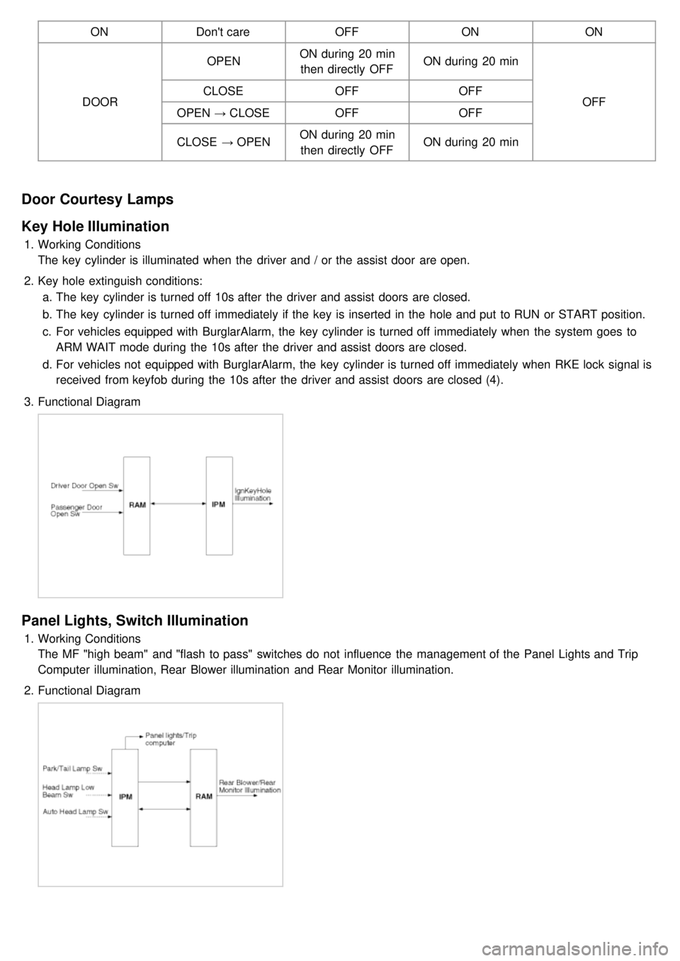
ONDon't care OFFONON
DOOR OPEN
ON during 20 min
then directly OFF ON during 20 min
OFF
CLOSE
OFFOFF
OPEN → CLOSE OFF OFF
CLOSE → OPEN ON during 20 min
then directly OFF ON during 20 min
Door Courtesy Lamps
Key Hole Illumination
1.
Working Conditions
The key cylinder is illuminated when the driver and / or the assist door are open.
2. Key hole extinguish conditions:
a. The key cylinder is turned off 10s after the driver and assist doors are closed.
b. The key cylinder is turned off immediately if the key is inserted in the hole and put to RUN or START position.
c. For vehicles equipped with BurglarAlarm, the key cylinder is turned off immediately when the system goes to
ARM WAIT mode during the 10s after the driver and assist doors are closed.
d. For vehicles not equipped with BurglarAlarm, the key cylinder is turned off immediately when RKE lock signal is
received from keyfob during the 10s after the driver and assist doors are closed (4).
3. Functional Diagram
Panel Lights, Switch Illumination
1.Working Conditions
The MF "high beam" and "flash to pass" switches do not influence the management of the Panel Lights and Trip
Computer illumination, Rear Blower illumination and Rear Monitor illumination.
2. Functional Diagram
Page 1233 of 1575
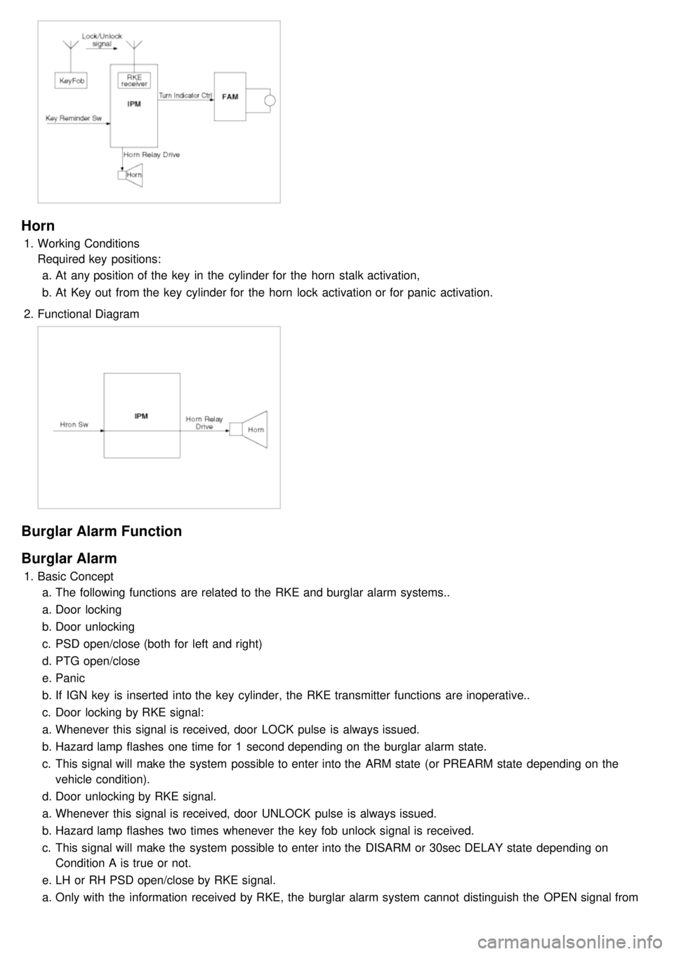
Horn
1.Working Conditions
Required key positions:
a. At any position of the key in the cylinder for the horn stalk activation,
b. At Key out from the key cylinder for the horn lock activation or for panic activation.
2. Functional Diagram
Burglar Alarm Function
Burglar Alarm
1.Basic Concept
a. The following functions are related to the RKE and burglar alarm systems..
a. Door locking
b. Door unlocking
c. PSD open/close (both for left and right)
d. PTG open/close
e. Panic
b. If IGN key is inserted into the key cylinder, the RKE transmitter functions are inoperative..
c. Door locking by RKE signal:
a. Whenever this signal is received, door LOCK pulse is always issued.
b. Hazard lamp flashes one time for 1 second depending on the burglar alarm state.
c. This signal will make the system possible to enter into the ARM state (or PREARM state depending on the
vehicle condition).
d. Door unlocking by RKE signal.
a. Whenever this signal is received, door UNLOCK pulse is always issued.
b. Hazard lamp flashes two times whenever the key fob unlock signal is received.
c. This signal will make the system possible to enter into the DISARM or 30sec DELAY state depending on
Condition A is true or not.
e. LH or RH PSD open/close by RKE signal.
a. Only with the information received by RKE, the burglar alarm system cannot distinguish the OPEN signal from
CLOSE signal.
Page 1234 of 1575
CLOSE signal.
b. RAM will pass this signal to LH PSD and RH PSD then the burglar alarm state is decided depending on the
vehicle condition.
f. PTG open/close
a. Only with the information received by RKE, the burglar alarm system cannot distinguish the OPEN signal from
CLOSE signal.
b. RAM will pass this signal to PTG module then the burglar alarm state is decided depending on the vehicle
condition.
g. Panic by key fob
a. Whenever this signal is received, the PANIC function is activated (unless the system is already in an ALARM
state).
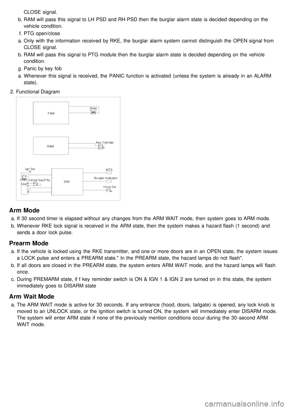
2. Functional Diagram
Arm Mode
a.If 30 second timer is elapsed without any changes from the ARM WAIT mode, then system goes to ARM mode.
b. Whenever RKE lock signal is received in the ARM state, then the system makes a hazard flash (1 second) and
sends a door lock pulse.
Prearm Mode
a.If the vehicle is locked using the RKE transmitter, and one or more doors are in an OPEN state, the system issues
a LOCK pulse and enters a PREARM state." In the PREARM state, the hazard lamps do not flash".
b. If all doors are closed in the PREARM state, the system enters ARM WAIT mode, and the hazard lamps will flash
once.
c. During PREMARM state, if f key reminder switch is ON & IGN 1 & IGN 2 are turned on in this state, the system
immediately goes to DISARM state
Arm Wait Mode
a.The ARM WAIT mode is active for 30 seconds. If any entrance (hood, doors, tailgate) is opened, any lock knob is
moved to an UNLOCK state, or the ignition switch is turned ON, the system will immediately enter DISARM mode.
The system will enter ARM state if none of the previously mention conditions occur during the 30- second ARM
WAIT mode.
Page 1235 of 1575
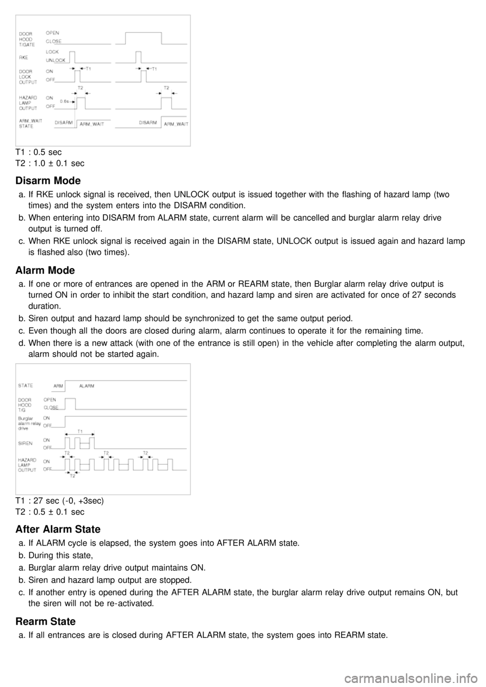
T1 : 0.5 sec
T2 : 1.0 ± 0.1 sec
Disarm Mode
a.If RKE unlock signal is received, then UNLOCK output is issued together with the flashing of hazard lamp (two
times) and the system enters into the DISARM condition.
b. When entering into DISARM from ALARM state, current alarm will be cancelled and burglar alarm relay drive
output is turned off.
c. When RKE unlock signal is received again in the DISARM state, UNLOCK output is issued again and hazard lamp
is flashed also (two times).
Alarm Mode
a.If one or more of entrances are opened in the ARM or REARM state, then Burglar alarm relay drive output is
turned ON in order to inhibit the start condition, and hazard lamp and siren are activated for once of 27 seconds
duration.
b. Siren output and hazard lamp should be synchronized to get the same output period.
c. Even though all the doors are closed during alarm, alarm continues to operate it for the remaining time.
d. When there is a new attack (with one of the entrance is still open) in the vehicle after completing the alarm output,
alarm should not be started again.
T1 : 27 sec ( - 0, +3sec)
T2 : 0.5 ± 0.1 sec
After Alarm State
a.If ALARM cycle is elapsed, the system goes into AFTER ALARM state.
b. During this state,
a. Burglar alarm relay drive output maintains ON.
b. Siren and hazard lamp output are stopped.
c. If another entry is opened during the AFTER ALARM state, the burglar alarm relay drive output remains ON, but
the siren will not be re- activated.
Rearm State
a.If all entrances are is closed during AFTER ALARM state, the system goes into REARM state.