2007 KIA CARNIVAL alarm
[x] Cancel search: alarmPage 1236 of 1575
Battery Removal
a.If the battery is removed with the system in the ARM state, the system will be placed into the ARM state upon
battery reconnect.
b. The ALARM state will be re- activated if the battery is disconnected, then reconnected, with the system in an
ALARM state.
c. If the battery is disconnected and reconnected with the system in AFTER ALARM state, the alarm will be re-
activated.
d. The system will enter DISARM mode if the battery is disconnected during the ALARM WAIT state.
Panic
a.If RKE PANIC signal is received, Siren output and hazard lamp operate for 27 seconds and the system return to
the previous state as soon as the PANIC function finishes.
b. The PANIC function will be stopped if any RKE signal is received during PANIC activation..
c. If Key reminder switch is ON during PANIC function is operating, PANIC is stopped immediately.
d. If the system goes to ALARM mode during PANIC function is operating, PANIC is stopped immediately and then
ALARM function should be activated.
e. During ALARM state;
If RKE PANIC signal is received, ALARM mode is maintained and PANIC function should be ignored. ALARM has
higher priority than PANIC function.
f. During AFTER_ALARM state;
If RKE PANIC signal is received, AFTR_ALARM mode is maintained and PANIC function should be activated.
Safe & Rescue Mode
The goal of those modes is to be able to cope with failures that may happen on some of the most critical
functionalities (for the driver security) of the system.
Safe Mode
The safe mode is entered in case of system problems such as:
a. Incoherent inputs on monitored signals. In this case, safe mode is the debouncing time before the inputs are
considered INVALID. Note that today, we have no way to detect if the rain/light sensor is in working operation or
not. It means that a driver action will be required in case of failure of this sensor;
b. Loss of the CAN frame containing the monitored signal:
c. Loss of the CAN network: CAN goes to BUS OFF state, safe mode is the time necessary for detecting the BUS
OFF state.
In all cases, the action in safe mode is to maintain the previous state of the system (for lighting and wiping). The list of
monitored signals is the same as in rescue mode
Exiting Safe Mode
The software safe mode is exited and the module goes back to the normal mode when: a. On IPM, hardware inputs return to a coherent state;
b. The lost CAN signal comes back while timeout has not elapsed;
c. The CAN network returns to a normal state without reaching BUS OFF state.
Software safe mode is also exited when the software rescue mode is entered (problem does not disappear).
Hardware safe mode is exited and the module goes back to normal mode if the internal problem disappears (watchdog
is properly triggered again). If the problem stays, hardware safe mode is exited to enter hardware rescue mode.
Rescue Modes
The rescue mode consists in activating some safety functions when IGN2 = ON: a. Switch on the low beams (FAM), park lamps (FAM), tail lamps (RAM) and cluster backlighting (IPM);
b. Unlock of all the doors when the rescue mode is entered with IGN2 = ON
c. Front wipers do not need to be turned on by software in rescue mode because wipers can be turned on by
manually setting the MF switch to low speed. The FAM software must keep the same state as before entering the
rescue mode.
d. When IGN2 = OFF, low beams, park/tail lamps and cluster backlighting are turned off.
Entering Rescue Modes
Page 1248 of 1575
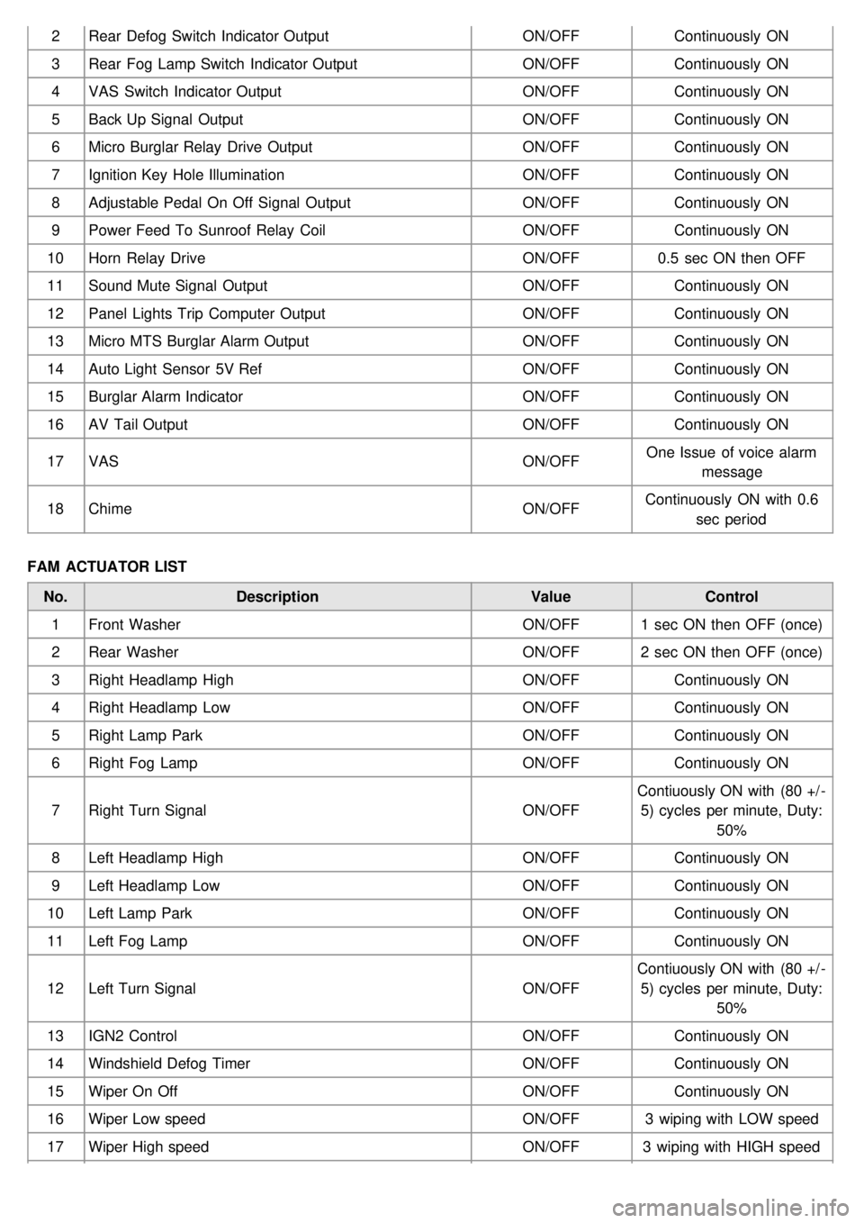
2Rear Defog Switch Indicator Output ON/OFFContinuously ON
3 Rear Fog Lamp Switch Indicator Output ON/OFFContinuously ON
4 VAS Switch Indicator Output ON/OFFContinuously ON
5 Back Up Signal Output ON/OFFContinuously ON
6 Micro Burglar Relay Drive Output ON/OFFContinuously ON
7 Ignition Key Hole Illumination ON/OFFContinuously ON
8 Adjustable Pedal On Off Signal Output ON/OFFContinuously ON
9 Power Feed To Sunroof Relay Coil ON/OFFContinuously ON
10 Horn Relay Drive ON/OFF0.5 sec ON then OFF
11 Sound Mute Signal Output ON/OFFContinuously ON
12 Panel Lights Trip Computer Output ON/OFFContinuously ON
13 Micro MTS Burglar Alarm Output ON/OFFContinuously ON
14 Auto Light Sensor 5V Ref ON/OFFContinuously ON
15 Burglar Alarm Indicator ON/OFFContinuously ON
16 AV Tail Output ON/OFFContinuously ON
17 VAS ON/OFFOne Issue of voice alarm
message
18 Chime ON/OFFContinuously ON with 0.6
sec period
FAM ACTUATOR LIST No. Description ValueControl
1 Front Washer ON/OFF1 sec ON then OFF (once)
2 Rear Washer ON/OFF2 sec ON then OFF (once)
3 Right Headlamp High ON/OFFContinuously ON
4 Right Headlamp Low ON/OFFContinuously ON
5 Right Lamp Park ON/OFFContinuously ON
6 Right Fog Lamp ON/OFFContinuously ON
7 Right Turn Signal ON/OFFContiuously ON with (80 +/ -
5) cycles per minute, Duty: 50%
8 Left Headlamp High ON/OFFContinuously ON
9 Left Headlamp Low ON/OFFContinuously ON
10 Left Lamp Park ON/OFFContinuously ON
11 Left Fog Lamp ON/OFFContinuously ON
12 Left Turn Signal ON/OFFContiuously ON with (80 +/ -
5) cycles per minute, Duty: 50%
13 IGN2 Control ON/OFFContinuously ON
14 Windshield Defog Timer ON/OFFContinuously ON
15 Wiper On Off ON/OFFContinuously ON
16 Wiper Low speed ON/OFF3 wiping with LOW speed
17 Wiper High speed ON/OFF3 wiping with HIGH speed
Page 1249 of 1575
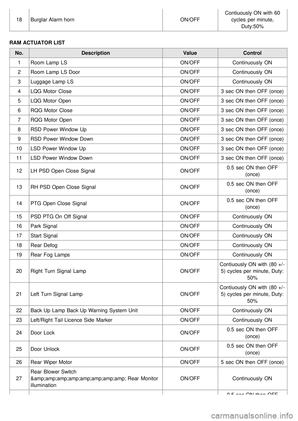
18Burglar Alarm horn ON/OFFContiuously ON with 60
cycles per minute, Duty:50%
RAM ACTUATOR LIST No. Description ValueControl
1 Room Lamp LS ON/OFFContinuously ON
2 Room Lamp LS Door ON/OFFContinuously ON
3 Luggage Lamp LS ON/OFFContinuously ON
4 LQG Motor Close ON/OFF3 sec ON then OFF (once)
5 LQG Motor Open ON/OFF3 sec ON then OFF (once)
6 RQG Motor Close ON/OFF3 sec ON then OFF (once)
7 RQG Motor Open ON/OFF3 sec ON then OFF (once)
8 RSD Power Window Up ON/OFF3 sec ON then OFF (once)
9 RSD Power Window Down ON/OFF3 sec ON then OFF (once)
10 LSD Power Window Up ON/OFF3 sec ON then OFF (once)
11 LSD Power Window Down ON/OFF3 sec ON then OFF (once)
12 LH PSD Open Close Signal ON/OFF0.5 sec ON then OFF
(once)
13 RH PSD Open Close Signal ON/OFF0.5 sec ON then OFF
(once)
14 PTG Open Close Signal ON/OFF0.5 sec ON then OFF
(once)
15 PSD PTG On Off Signal ON/OFFContinuously ON
16 Park Signal ON/OFFContinuously ON
17 Start Signal ON/OFFContinuously ON
18 Rear Defog ON/OFFContinuously ON
19 Rear Fog Lamps ON/OFFContinuously ON
20 Right Turn Signal Lamp ON/OFFContiuously ON with (80 +/ -
5) cycles per minute, Duty: 50%
21 Left Turn Signal Lamp ON/OFFContiuously ON with (80 +/ -
5) cycles per minute, Duty: 50%
22 Back Up Lamp Back Up Warning System Unit ON/OFFContinuously ON
23 Left/Right Tail Licence Side Marker ON/OFFContinuously ON
24 Door Lock ON/OFF0.5 sec ON then OFF
(once)
25 Door Unlock ON/OFF0.5 sec ON then OFF
(once)
26 Rear Wiper Motor ON/OFF5 sec ON then OFF (once)
27 Rear Blower Switch
& Rear Monitor
illumination ON/OFF
Continuously ON
0.5 sec ON then OFF
Page 1262 of 1575
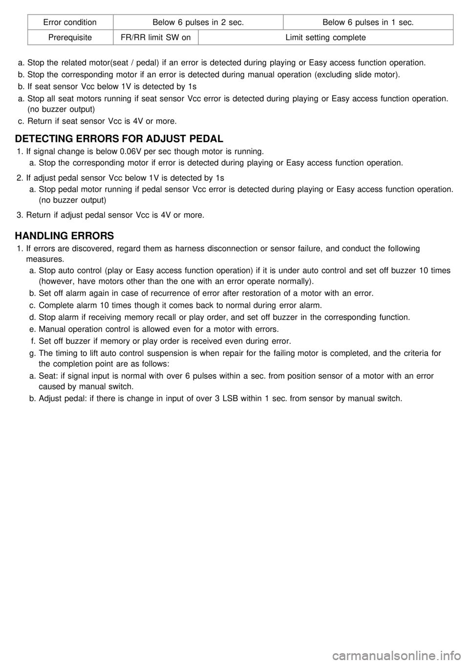
Error conditionBelow 6 pulses in 2 sec. Below 6 pulses in 1 sec.
Prerequisite FR/RR limit SW on Limit setting complete
a. Stop the related motor(seat / pedal) if an error is detected during playing or Easy access function operation.
b. Stop the corresponding motor if an error is detected during manual operation (excluding slide motor).
b. If seat sensor Vcc below 1V is detected by 1s
a. Stop all seat motors running if seat sensor Vcc error is detected during playing or Easy access function operation.
(no buzzer output)
c. Return if seat sensor Vcc is 4V or more.
DETECTING ERRORS FOR ADJUST PEDAL
1.If signal change is below 0.06V per sec though motor is running.
a. Stop the corresponding motor if error is detected during playing or Easy access function operation.
2. If adjust pedal sensor Vcc below 1V is detected by 1s
a. Stop pedal motor running if pedal sensor Vcc error is detected during playing or Easy access function operation.
(no buzzer output)
3. Return if adjust pedal sensor Vcc is 4V or more.
HANDLING ERRORS
1.If errors are discovered, regard them as harness disconnection or sensor failure, and conduct the following
measures.
a. Stop auto control (play or Easy access function operation) if it is under auto control and set off buzzer 10 times
(however, have motors other than the one with an error operate normally).
b. Set off alarm again in case of recurrence of error after restoration of a motor with an error.
c. Complete alarm 10 times though it comes back to normal during error alarm.
d. Stop alarm if receiving memory recall or play order, and set off buzzer in the corresponding function.
e. Manual operation control is allowed even for a motor with errors.
f. Set off buzzer if memory or play order is received even during error.
g. The timing to lift auto control suspension is when repair for the failing motor is completed, and the criteria for
the completion point are as follows:
a. Seat: if signal input is normal with over 6 pulses within a sec. from position sensor of a motor with an error
caused by manual switch.
b. Adjust pedal: if there is change in input of over 3 LSB within 1 sec. from sensor by manual switch.
Page 1503 of 1575
2007 > 2.7L V6 GASOLINE >
DESCRIPTION
The immobilizer system will disable the vehicle unless the proper ignition key is used, in addition to the currently
available anti- theft systems such as car alarms, the immobilizer system aims to drastically reduce the rate of auto
theft.
1. SMARTRA type immobilizer
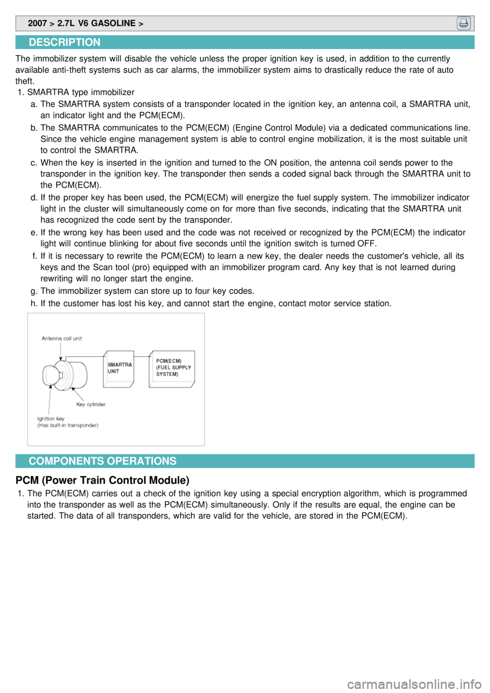
a. The SMARTRA system consists of a transponder located in the ignition key, an antenna coil, a SMARTRA unit,
an indicator light and the PCM(ECM).
b. The SMARTRA communicates to the PCM(ECM) (Engine Control Module) via a dedicated communications line.
Since the vehicle engine management system is able to control engine mobilization, it is the most suitable unit
to control the SMARTRA.
c. When the key is inserted in the ignition and turned to the ON position, the antenna coil sends power to the
transponder in the ignition key. The transponder then sends a coded signal back through the SMARTRA unit to
the PCM(ECM).
d. If the proper key has been used, the PCM(ECM) will energize the fuel supply system. The immobilizer indicator
light in the cluster will simultaneously come on for more than five seconds, indicating that the SMARTRA unit
has recognized the code sent by the transponder.
e. If the wrong key has been used and the code was not received or recognized by the PCM(ECM) the indicator
light will continue blinking for about five seconds until the ignition switch is turned OFF.
f. If it is necessary to rewrite the PCM(ECM) to learn a new key, the dealer needs the customer's vehicle, all its
keys and the Scan tool (pro) equipped with an immobilizer program card. Any key that is not learned during
rewriting will no longer start the engine.
g. The immobilizer system can store up to four key codes.
h. If the customer has lost his key, and cannot start the engine, contact motor service station.
COMPONENTS OPERATIONS
PCM (Power Train Control Module)
1. The PCM(ECM) carries out a check of the ignition key using a special encryption algorithm, which is programmed
into the transponder as well as the PCM(ECM) simultaneously. Only if the results are equal, the engine can be
started. The data of all transponders, which are valid for the vehicle, are stored in the PCM(ECM).
Page 1533 of 1575
2007 > 2.7L V6 GASOLINE >
DESCRIPTION
When reversing, the driver is not easy to find objects in the blind spots and to determine the distance from the object.
In order to provide the driver safety and convenience, back warning system will operate upon shifting to "R" Ultrasonic
sensor will emit ultrasonic wave rearward and detect the reflected wave. Control unit will calculate distance to the
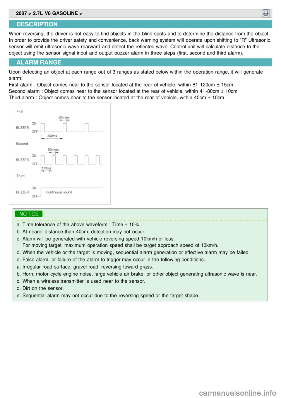
object using the sensor signal input and output buzzer alarm in three steps (first, second and third alarm).
ALARM RANGE
Upon detecting an object at each range out of 3 ranges as stated below within the operation range, it will generate
alarm.
First alarm : Object comes near to the sensor located at the rear of vehicle, within 81- 120cm ± 15cm
Second alarm : Object comes near to the sensor located at the rear of vehicle, within 41- 80cm ± 10cm
Third alarm : Object comes near to the sensor located at the rear of vehicle, within 40cm ± 10cm
a.Time tolerance of the above waveform : Time ± 10%
b. At nearer distance than 40cm, detection may not occur.
c. Alarm will be generated with vehicle reversing speed 10km/h or less.
For moving target, maximum operation speed shall be target approach speed of 10km/h.
d. When the vehicle or the target is moving, sequential alarm generation or effective alarm may be failed.
e. False alarm, or failure of the alarm to trigger may occur in the following conditions.
a. Irregular road surface, gravel road, reversing toward grass.
b. Horn, motor cycle engine noise, large vehicle air brake, or other object generating ultrasonic wave is near.
c. When a wireless transmitter is used near to the sensor.
d. Dirt on the sensor.
e. Sequential alarm may not occur due to the reversing speed or the target shape.
Page 1535 of 1575
2007 > 2.7L V6 GASOLINE >
DIAGNOSIS
1.DIAGNOSIS
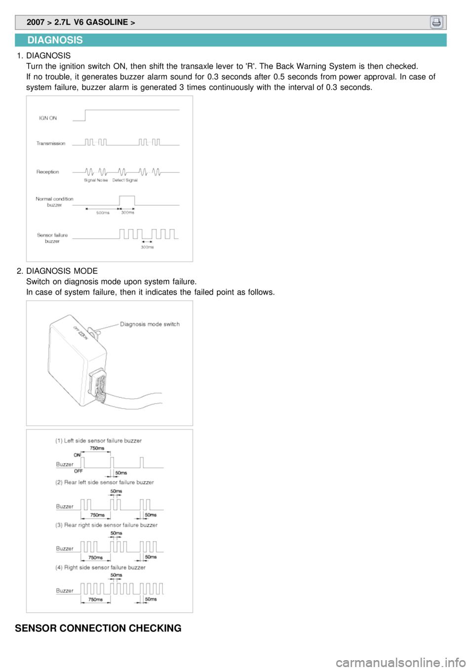
Turn the ignition switch ON, then shift the transaxle lever to 'R'. The Back Warning System is then checked.
If no trouble, it generates buzzer alarm sound for 0.3 seconds after 0.5 seconds from power approval. In case of
system failure, buzzer alarm is generated 3 times continuously with the interval of 0.3 seconds.
2.DIAGNOSIS MODE
Switch on diagnosis mode upon system failure.
In case of system failure, then it indicates the failed point as follows.
SENSOR CONNECTION CHECKING
Page 1537 of 1575
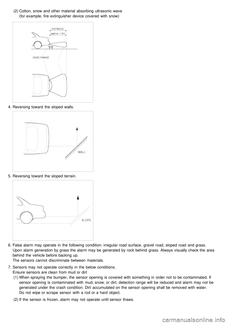
(2)Cotton, snow and other material absorbing ultrasonic wave
(for example, fire extinguisher device covered with snow)
4.Reversing toward the sloped walls.
5.Reversing toward the sloped terrain.
6.False alarm may operate in the following condition: irregular road surface, gravel road, sloped road and grass.
Upon alarm generation by grass the alarm may be generated by rock behind grass. Always visually check the area
behind the vehicle before backing up.
The sensors cannot discriminate between materials.
7. Sensors may not operate correctly in the below conditions.
Ensure sensors are clean from mud or dirt
(1) When spraying the bumper, the sensor opening is covered with something in order not to be contaminated. If
sensor opening is contaminated with mud, snow, or dirt, detection range will be reduced and alarm may not be
generated under the crash condition. Dirt accumulated on the sensor opening shall be removed with water.
Do not wipe or scrape sensor with a rod or a hard object.
(2) If the sensor is frozen, alarm may not operate until sensor thaws.