Page 1038 of 1575
2.After disconnecting the connector (B), remove the power window motor (A).
3.Installation is the reverse of removal.
a.Roll the glass up and down to see if it move will freely without binding.
OUT SIDE HANDLE REPLACEMENT
1.Remove the following items.
a. Door trim.
b. Door trim seal.
c. Actuator.
2. Loosen the mounting bolt, then remove the outside handle bracket (A).
3.Remove the outside handle (A).
Page 1040 of 1575
2.Disconnect the connector (B).
3. After loose the dooring module mounting nuts, remove the window regulator (A).
4.Installation is the reverse of removal.
a.Make sure the connector is plugged in properly and each rod is connected securely.
b. Make sure the door lock and open properly.
INSIDE HANDLE REPLACEMENT
1.Disconnect the clip (A), remove the inside handle (B).
2.Installation is the reverse of removal.
a.Make sure the door lock and open properly.
CHANNEL REPLACEMENT
1.Remove the door trim.
2. Remove the glass.
3. Loosen the channel mounting nuts, remove the channel (A).
Page 1100 of 1575
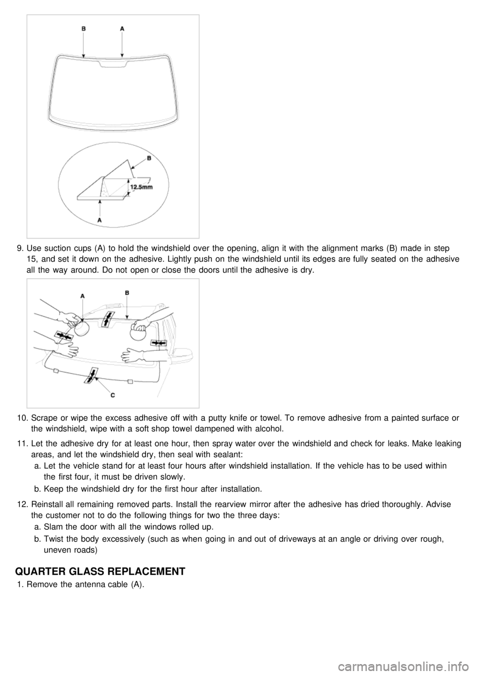
9.Use suction cups (A) to hold the windshield over the opening, align it with the alignment marks (B) made in step
15, and set it down on the adhesive. Lightly push on the windshield until its edges are fully seated on the adhesive
all the way around. Do not open or close the doors until the adhesive is dry.
10. Scrape or wipe the excess adhesive off with a putty knife or towel. To remove adhesive from a painted surface or
the windshield, wipe with a soft shop towel dampened with alcohol.
11. Let the adhesive dry for at least one hour, then spray water over the windshield and check for leaks. Make leaking
areas, and let the windshield dry, then seal with sealant:
a. Let the vehicle stand for at least four hours after windshield installation. If the vehicle has to be used within
the first four, it must be driven slowly.
b. Keep the windshield dry for the first hour after installation.
12. Reinstall all remaining removed parts. Install the rearview mirror after the adhesive has dried thoroughly. Advise
the customer not to do the following things for two the three days:
a. Slam the door with all the windows rolled up.
b. Twist the body excessively (such as when going in and out of driveways at an angle or driving over rough,
uneven roads)
QUARTER GLASS REPLACEMENT
1.Remove the antenna cable (A).
Page 1211 of 1575
2007 > 2.7L V6 GASOLINE >
DESCRIPTION
All modules are linked a low speed CAN network.
The input information for the modules is coming from both the CAN network and the hardware components
(actuatorsand sensors).
a. FAM (Front Area Module)
a. Headlamp low/high beam control (with DRL)
b. Park lamp control
c. Front fog lamp control
d. Front turn signal lamp control
e. Windshield wiper control
f. Windshield deicer
g. Diagnostics
b. IPM (In - Panel Module)
a. RKE (Remote Keyless Control)
b. VAS (Voice Alarm System)
c. Ignition key hole illumination
d. Switch indicators control
e. Panel light control
f. Seat belt warning
g. Auto light/DRL control (Logic)
h. Windshield/Rear wiper control (Logic)
i. Turn and Hazard lamp control (Logic)
j. Central door lock (Logic)
k. Windshield deicer timer
l. Rear glass defog timer
m. Gateway for ISO- 9141 (K- Line)
c. RAM (Rear Area Module)
a. Tail lamp control
b. Turn and Hazard lamp control
c. Back up lamp control
d. Rea fog lamp control
e. Stop lamp outage detection
f. Sliding door power window/Quarter glass control
g. Room lamp control
h. Rear wiper control
i. Rear glass defog
j. Fuel filler door open solenoid control
d. ADM (Assist Drive Module)
e. DDM (Driver Drive Module)
MODULE INTRODUCTION
FAM/IPM/RAM consists of a power board and an electronic board. The power board contains circuit protection devices
and switching devices. The electronic board uses Intelligent Power Switching (IPS) for HS/LS load control, logic
functions and CAN/K- Line communication. The power board and electronic board are connected with pin blocks for
the Front Area Module (FAM) and VCD (Variable Connection Displacement) for the In- Panel Module (IPM) and the
Rear Area Module (RAM).
Page 1224 of 1575
3.Functional Diagram
Comfort Function
Power Windows
1.The purpose of the power window function is to manage the driver and assist power window motors. This function
is entirely implemented in the DDM and ADM (door modules) and DMS role for this function is limited to providing
signals through the CAN bus.
Power Seat With Memory Interface
This function manages the power seat and the associated memorized positions. This function is entirely implemented
in the IMS (seat module) and DMS role for this function is limited to providing signals through the CAN bus.
Adjustable Pedal
Adjustable Pedal With Memory Interface(ims)
1.This function is implemented by the IMS. This function adjusts the pedal position when the pedal backward/forward
switch is pressed.
2. Functional Diagram
Page 1225 of 1575
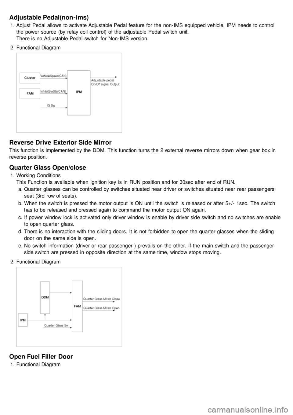
Adjustable Pedal(non-ims)
1.Adjust Pedal allows to activate Adjustable Pedal feature for the non- IMS equipped vehicle, IPM needs to control
the power source (by relay coil control) of the adjustable Pedal switch unit.
There is no Adjustable Pedal switch for Non- IMS version.
2. Functional Diagram
Reverse Drive Exterior Side Mirror
This function is implemented by the DDM. This function turns the 2 external reverse mirrors down when gear box in
reverse position.
Quarter Glass Open/close
1.Working Conditions
This Function is available when Ignition key is in RUN position and for 30sec after end of RUN.
a. Quarter glasses can be controlled by switches situated near driver or switches situated near rear passengers
seat (3rd row of seats).
b. When the switch is pressed the motor output is ON until the switch is released or after 5+/- 1sec. The switch
has to be released and pressed again to command the motor output ON again.
c. If power window lock is activated only driver window is enable by driver side switch and no switches are enable
to open quarter glass.
d. There is no interaction with the sliding doors. It is not forbidden to open the quarter glasses when the sliding
door on the same side is open.
e. No switch information (driver or rear passenger ) prevails on the other. If the main switch and the passenger
side switch are pressed in opposite direction at the same time, window stops moving.
2. Functional Diagram
Open Fuel Filler Door
1.Functional Diagram
Page 1226 of 1575
Sun Roof Relay Coil
This function defines the condition for switching on or off power feed to sun roof relay coil. This function is available in
RUN position and during after run timer ON.
Power Window Timer
This function defines the conditions for allowing use of power windows, quarter glass, and feed to sunroof relay coil.
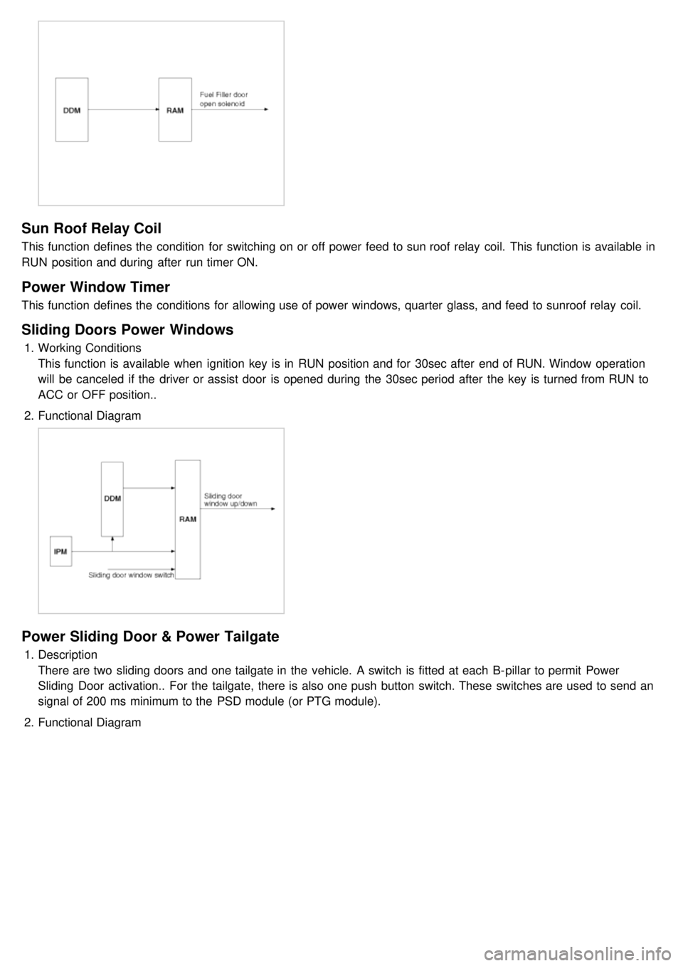
Sliding Doors Power Windows
1.Working Conditions
This function is available when ignition key is in RUN position and for 30sec after end of RUN. Window operation
will be canceled if the driver or assist door is opened during the 30sec period after the key is turned from RUN to
ACC or OFF position..
2. Functional Diagram
Power Sliding Door & Power Tailgate
1.Description
There are two sliding doors and one tailgate in the vehicle. A switch is fitted at each B- pillar to permit Power
Sliding Door activation.. For the tailgate, there is also one push button switch. These switches are used to send an
signal of 200 ms minimum to the PSD module (or PTG module).
2. Functional Diagram
Page 1231 of 1575
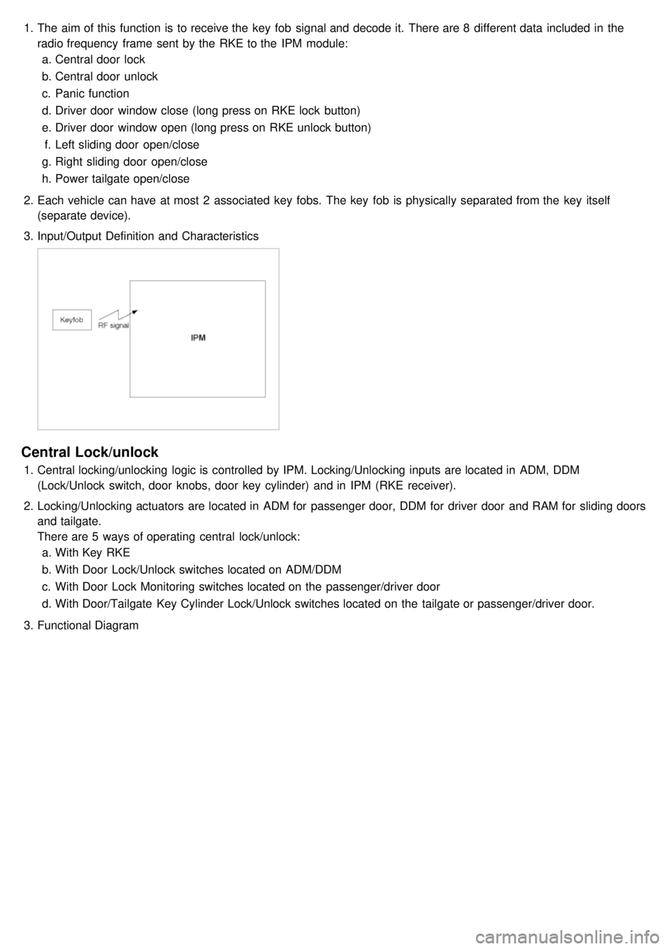
1.The aim of this function is to receive the key fob signal and decode it. There are 8 different data included in the
radio frequency frame sent by the RKE to the IPM module:
a. Central door lock
b. Central door unlock
c. Panic function
d. Driver door window close (long press on RKE lock button)
e. Driver door window open (long press on RKE unlock button)
f. Left sliding door open/close
g. Right sliding door open/close
h. Power tailgate open/close
2. Each vehicle can have at most 2 associated key fobs. The key fob is physically separated from the key itself
(separate device).
3. Input/Output Definition and Characteristics
Central Lock/unlock
1.Central locking/unlocking logic is controlled by IPM. Locking/Unlocking inputs are located in ADM, DDM
(Lock/Unlock switch, door knobs, door key cylinder) and in IPM (RKE receiver).
2. Locking/Unlocking actuators are located in ADM for passenger door, DDM for driver door and RAM for sliding doors
and tailgate.
There are 5 ways of operating central lock/unlock:
a. With Key RKE
b. With Door Lock/Unlock switches located on ADM/DDM
c. With Door Lock Monitoring switches located on the passenger/driver door
d. With Door/Tailgate Key Cylinder Lock/Unlock switches located on the tailgate or passenger/driver door.
3. Functional Diagram