2007 KIA CARNIVAL fault codes
[x] Cancel search: fault codesPage 239 of 1575
2007 > 2.7L V6 GASOLINE >
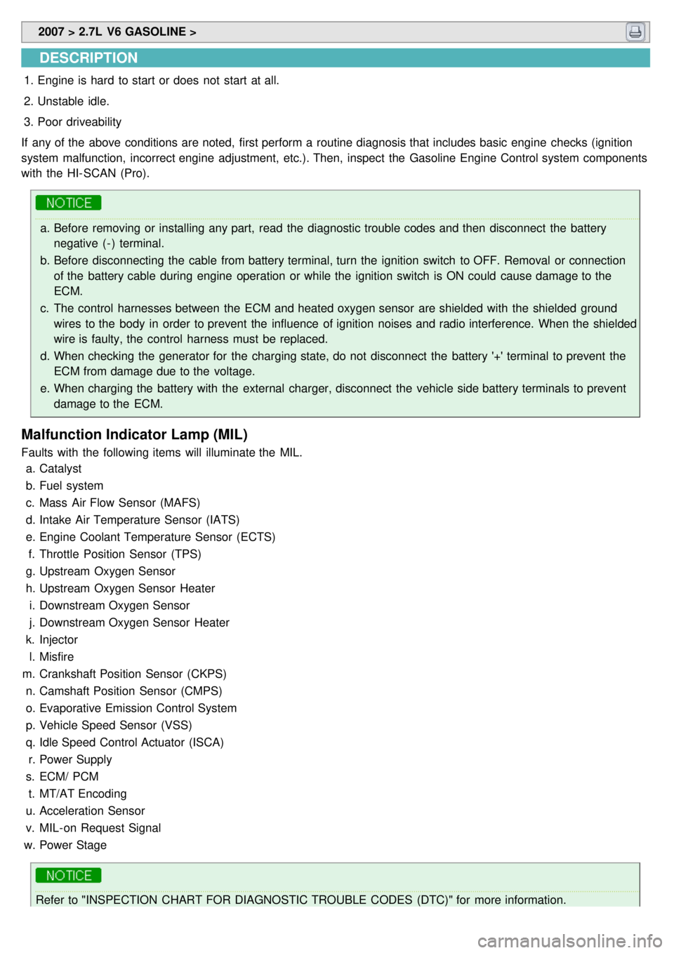
DESCRIPTION
1.Engine is hard to start or does not start at all.
2. Unstable idle.
3. Poor driveability
If any of the above conditions are noted, first perform a routine diagnosis that includes basic engine checks (ignition
system malfunction, incorrect engine adjustment, etc.). Then, inspect the Gasoline Engine Control system components
with the HI- SCAN (Pro).
a. Before removing or installing any part, read the diagnostic trouble codes and then disconnect the battery
negative ( - ) terminal.
b. Before disconnecting the cable from battery terminal, turn the ignition switch to OFF. Removal or connection
of the battery cable during engine operation or while the ignition switch is ON could cause damage to the
ECM.
c. The control harnesses between the ECM and heated oxygen sensor are shielded with the shielded ground
wires to the body in order to prevent the influence of ignition noises and radio interference. When the shielded
wire is faulty, the control harness must be replaced.
d. When checking the generator for the charging state, do not disconnect the battery '+' terminal to prevent the
ECM from damage due to the voltage.
e. When charging the battery with the external charger, disconnect the vehicle side battery terminals to prevent
damage to the ECM.
Malfunction Indicator Lamp (MIL)
Faults with the following items will illuminate the MIL.
a. Catalyst
b. Fuel system
c. Mass Air Flow Sensor (MAFS)
d. Intake Air Temperature Sensor (IATS)
e. Engine Coolant Temperature Sensor (ECTS)
f. Throttle Position Sensor (TPS)
g. Upstream Oxygen Sensor
h. Upstream Oxygen Sensor Heater
i. Downstream Oxygen Sensor
j. Downstream Oxygen Sensor Heater
k. Injector
l. Misfire
m. Crankshaft Position Sensor (CKPS)
n. Camshaft Position Sensor (CMPS)
o. Evaporative Emission Control System
p. Vehicle Speed Sensor (VSS)
q. Idle Speed Control Actuator (ISCA)
r. Power Supply
s. ECM/ PCM
t. MT/AT Encoding
u. Acceleration Sensor
v. MIL- on Request Signal
w. Power Stage
Refer to "INSPECTION CHART FOR DIAGNOSTIC TROUBLE CODES (DTC)" for more information.
Page 240 of 1575
Faults with the following items will illuminate the MILa. Heated oxygen sensor (HO2S)
b. Mass Air Flow sensor (MAFS)
c. Throttle position sensor (TPS)
d. Engine coolant temperature sensor (ECTS)
e. Idle speed control actuator (ISCA)
f. Injectors
g. ECM
Refer to "INSPECTION CHART FOR DIAGNOSTIC TROUBLE CODES (DTC)" for more information.
1. After turning ON the ignition key, ensure that the light illuminates for about 5 seconds and then goes out.
2. If the light does not illuminate, check for an open circuit in the harness, a blown fuse or a blown bulb.
Self-Diagnosis
If a sensor connector is disconnected with the ignition switch turned on, the diagnostic trouble code (DTC) is
recorded. In this case, disconnect the battery negative terminal ( - ) for 15 seconds or more, and the diagnosis
memory will be erased.
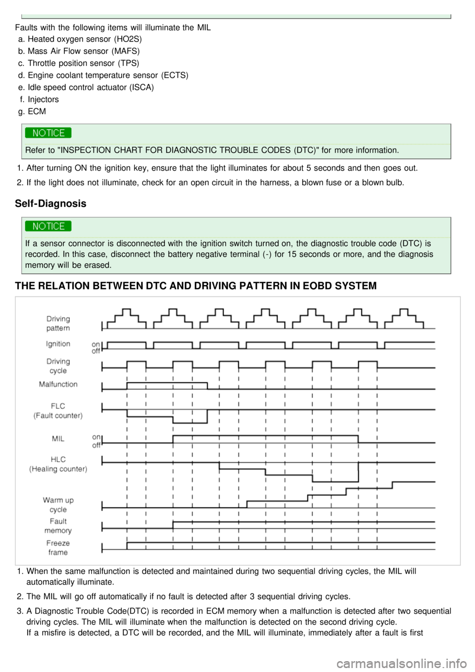
THE RELATION BETWEEN DTC AND DRIVING PATTERN IN EOBD SYSTEM
1.When the same malfunction is detected and maintained during two sequential driving cycles, the MIL will
automatically illuminate.
2. The MIL will go off automatically if no fault is detected after 3 sequential driving cycles.
3. A Diagnostic Trouble Code(DTC) is recorded in ECM memory when a malfunction is detected after two sequential
driving cycles. The MIL will illuminate when the malfunction is detected on the second driving cycle.
If a misfire is detected, a DTC will be recorded, and the MIL will illuminate, immediately after a fault is first
detected.
Page 795 of 1575

2007 > 2.7L V6 GASOLINE >
General
The supplemental restraint system (SRS) is designed to supplement the seat belt to help reduce the risk or severity of
injury to the driver and passenger by activating and deploying the driver, passenger, side airbag and belt pretensioner
in certain frontal or side collisions.
The SRS (Airbag) consists of : a driver side airbag module located in the center of the steering wheel, which contains
the folded cushion and an inflator unit ; a passenger side airbag module located in the passenger side crash pad
contains the folded cushion assembled with inflator unit ; side airbag modules located in the driver and passenger seat
contain the folded cushion and an inflator unit ; curtain airbag modules located inside of the headliner which contains
folded cushions and inflator units. The impact sensing function of the SRSCM is carried out by electronic
accelerometer that continuously measure the vehicle's acceleration and delivers a corresponding signal through
amplifying and filtering circuitry to the microprocessor.
SRSCM (SRS Control Module)
SRSCM will detect front impact with front impact sensor, and side impact with side impact sensor, and determine
airbag module deployment.
1. DC/DC converter: DC/DC converter in power supply unit includes up/down transformer converter, and provide
ignition voltage for 2 front airbag ignition circuits and the internal operation voltage of the SRSCM. If the internal
operation voltage is below critical value setting, it will perform resetting.
2. Safety sensor: Safety sensor is located in airbag ignition circuit. Safety sensor will operate airbag circuit at any
deployment condition and release airbag circuit safely at normal driving condition. Safety sensor is a double contact
electro - mechanical switch that will close detecting deceleration above certain criteria.
3. Back up power supply: SRSCM has separate back up power supply, that will supply deployment energy instantly in
low voltage condition or upon power failure by front crash.
4. Self diagnosis: SRSCM will constantly monitor current SRS operation status and detect system failure while vehicle
power supply is on, system failure may be checked with trouble codes using scan tool. (Hi- Scan)
5. Airbag warning lamp on: Upon detecting error, the module will transmit signal to SRSCM indicator lamp located at
cluster. MIL lamp will indicate driver SRS error. Upon ignition key on, SRS lamp will turn on for about six seconds.
6. Trouble code registration: Upon error occurrence in system, SRSCM will store DTC corresponding to the error.
DTC can be cleared only by Hi - Scan. However, if an internal fault code is logged or if a crash is recorded the fault
clearing should not happen.
7. Self diagnostic connector: Data stored in SRSCM memory will be output to Hi - Scan or other external output
devices through connector located below driver side crash pad.
8. Once airbag is deployed, SRSCM should not be used again but replaced.
9. SRSCM will determine whether passenger put on seat belt by the signal from built- in switch in seat belt buckle, and
deploy front seat airbag at each set crash speed.
10. Side airbag deployment will be determined by SRSCM that will detect satellite sensor impact signal upon side
crash, irrespective to seat belt condition.
Page 809 of 1575
![KIA CARNIVAL 2007 Workshop Manual DIAGNOSTIC TROUBLE CODES (DTC)
DTCFAULT DESCRIPTION PAGE
B1101 Battery Voltage too High
B1102 Battery Voltage too Low
B1328 Front Impact Sensor [Driver] Defect
B1329 Front Impact Sensor [Dri KIA CARNIVAL 2007 Workshop Manual DIAGNOSTIC TROUBLE CODES (DTC)
DTCFAULT DESCRIPTION PAGE
B1101 Battery Voltage too High
B1102 Battery Voltage too Low
B1328 Front Impact Sensor [Driver] Defect
B1329 Front Impact Sensor [Dri](/manual-img/2/57045/w960_57045-808.png)
DIAGNOSTIC TROUBLE CODES (DTC)
DTCFAULT DESCRIPTION PAGE
B1101 Battery Voltage too High
B1102 Battery Voltage too Low
B1328 Front Impact Sensor [Driver] Defect
B1329 Front Impact Sensor [Driver] Communication Error
B1333 Front Impact Sensor [Passenger] Defect
B1334 Front Impact Sensor [Passenger] Communication Error
B1346 Driver Airbag Resistance too High
B1347 Driver Airbag Resistance too Low
Page 935 of 1575

3.Turn the ignition switch ON.
4. Check for DTC using the Scan tool
5. After completion trouble of the repair or correction of the problem, erase the stored fault codes using the scan tool.
6. Disconnect the Scan tool from the 16P data link connector.
ABS CHECK SHEET
Page 1332 of 1575
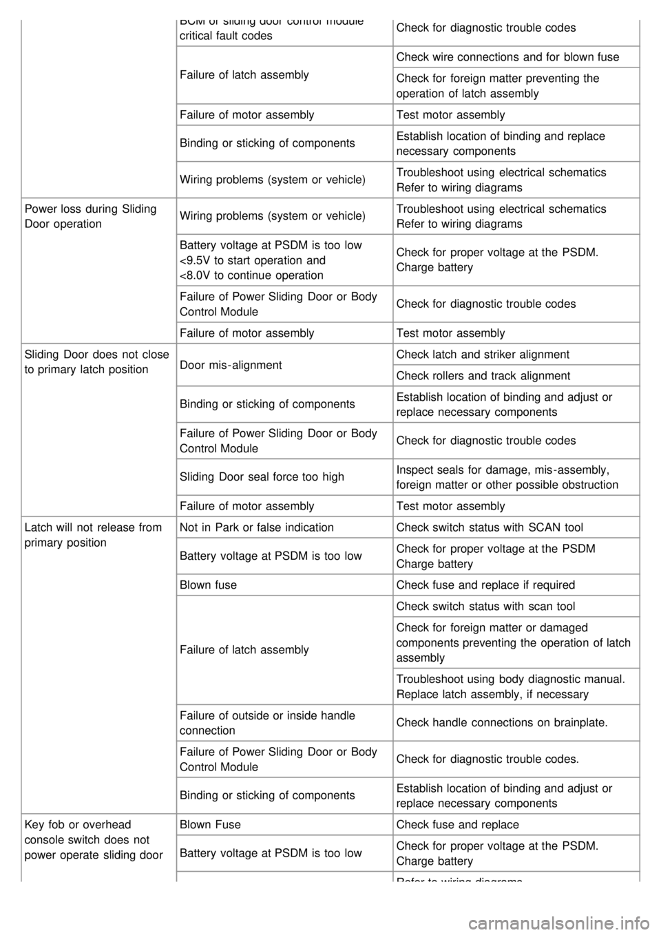
BCM or sliding door control module
critical fault codesCheck for diagnostic trouble codes
Failure of latch assembly Check wire connections and for blown fuse
Check for foreign matter preventing the
operation of latch assembly
Failure of motor assembly Test motor assembly
Binding or sticking of components Establish location of binding and replace
necessary components
Wiring problems (system or vehicle) Troubleshoot using electrical schematics
Refer to wiring diagrams
Power loss during Sliding
Door operation Wiring problems (system or vehicle)
Troubleshoot using electrical schematics
Refer to wiring diagrams
Battery voltage at PSDM is too low
<9.5V to start operation and
<8.0V to continue operation Check for proper voltage at the PSDM.
Charge battery
Failure of Power Sliding Door or Body
Control Module Check for diagnostic trouble codes
Failure of motor assembly Test motor assembly
Sliding Door does not close
to primary latch position Door mis - alignment Check latch and striker alignment
Check rollers and track alignment
Binding or sticking of components Establish location of binding and adjust or
replace necessary components
Failure of Power Sliding Door or Body
Control Module Check for diagnostic trouble codes
Sliding Door seal force too high Inspect seals for damage, mis - assembly,
foreign matter or other possible obstruction
Failure of motor assembly Test motor assembly
Latch will not release from
primary position Not in Park or false indication
Check switch status with SCAN tool
Battery voltage at PSDM is too low Check for proper voltage at the PSDM
Charge battery
Blown fuse Check fuse and replace if required
Failure of latch assembly Check switch status with scan tool
Check for foreign matter or damaged
components preventing the operation of latch
assembly
Troubleshoot using body diagnostic manual.
Replace latch assembly, if necessary
Failure of outside or inside handle
connection Check handle connections on brainplate.
Failure of Power Sliding Door or Body
Control Module Check for diagnostic trouble codes.
Binding or sticking of components Establish location of binding and adjust or
replace necessary components
Key fob or overhead
console switch does not
power operate sliding door Blown Fuse
Check fuse and replace
Battery voltage at PSDM is too low Check for proper voltage at the PSDM.
Charge battery
Refer to wiring diagrams
Page 1372 of 1575
2007 > 2.7L V6 GASOLINE >
DIAGNOSIS AND TESTING - POWER TAILGATE SYSTEM
The power tailgate system is a complex system containing many components. In order to perform conclusive testing,
or receive outputs the power tailgate control module must be checked.
The most reliable, efficient, and accurate means to diagnose the power tailgate system requires the use of a scan tool
and the proper Body Diagnostic Procedures manual. The scan tool can be used to observe current switch status
recorded in the power tailgate control module to help the technician diagnose an inoperative switch.
Before any testing of the power tailgate system is attempted, the battery should be fully charged, all power tailgate
system inhibitors read and understood (Refer to power tailgate system description for list).
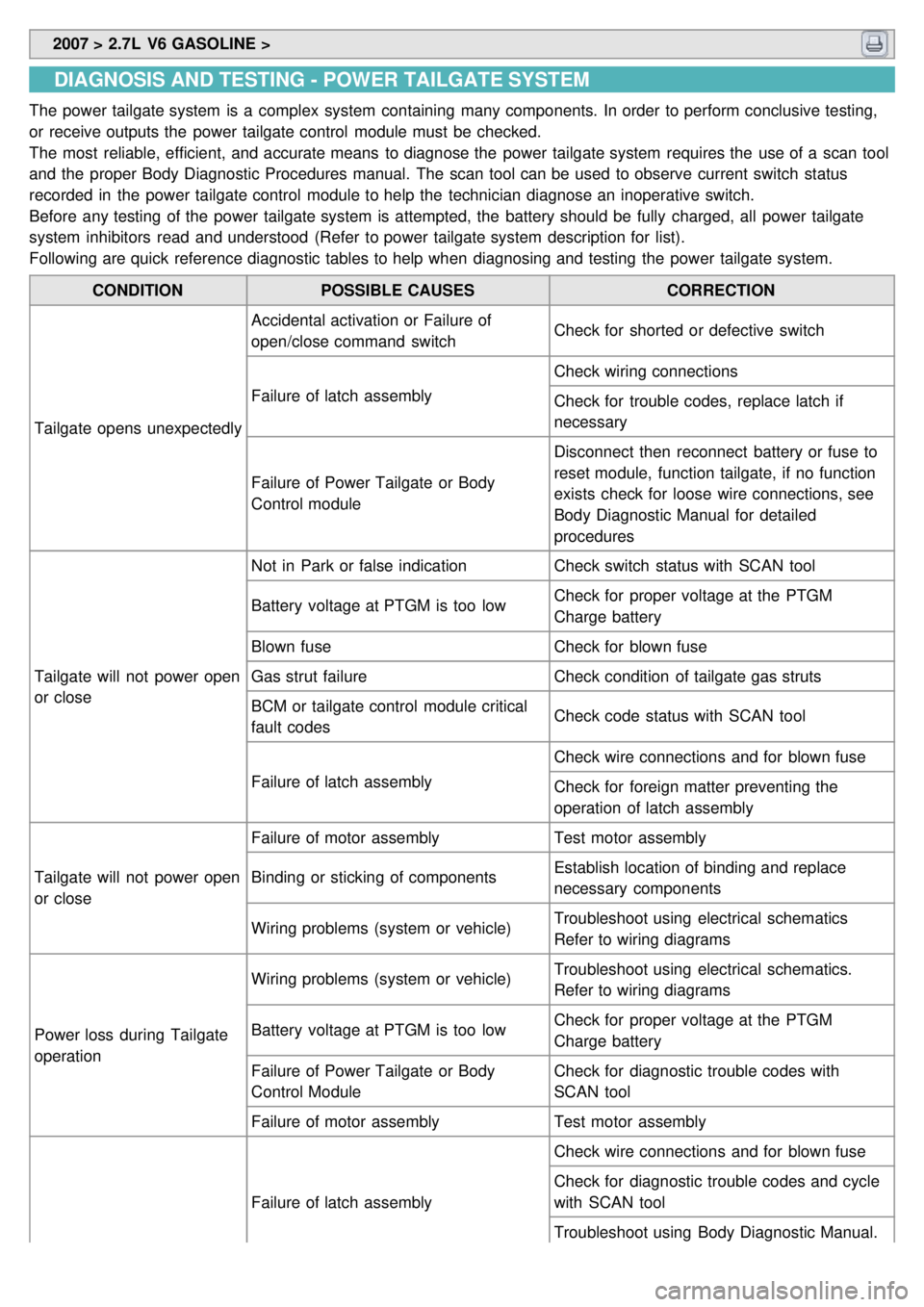
Following are quick reference diagnostic tables to help when diagnosing and testing the power tailgate system.
CONDITION POSSIBLE CAUSES CORRECTION
Tailgate opens unexpectedly Accidental activation or Failure of
open/close command switch
Check for shorted or defective switch
Failure of latch assembly Check wiring connections
Check for trouble codes, replace latch if
necessary
Failure of Power Tailgate or Body
Control module Disconnect then reconnect battery or fuse to
reset module, function tailgate, if no function
exists check for loose wire connections, see
Body Diagnostic Manual for detailed
procedures
Tailgate will not power open
or close Not in Park or false indication
Check switch status with SCAN tool
Battery voltage at PTGM is too low Check for proper voltage at the PTGM
Charge battery
Blown fuse Check for blown fuse
Gas strut failure Check condition of tailgate gas struts
BCM or tailgate control module critical
fault codes Check code status with SCAN tool
Failure of latch assembly Check wire connections and for blown fuse
Check for foreign matter preventing the
operation of latch assembly
Tailgate will not power open
or close Failure of motor assembly
Test motor assembly
Binding or sticking of components Establish location of binding and replace
necessary components
Wiring problems (system or vehicle) Troubleshoot using electrical schematics
Refer to wiring diagrams
Power loss during Tailgate
operation Wiring problems (system or vehicle)
Troubleshoot using electrical schematics.
Refer to wiring diagrams
Battery voltage at PTGM is too low Check for proper voltage at the PTGM
Charge battery
Failure of Power Tailgate or Body
Control Module Check for diagnostic trouble codes with
SCAN tool
Failure of motor assembly Test motor assembly
Failure of latch assembly Check wire connections and for blown fuse
Check for diagnostic trouble codes and cycle
with SCAN tool
Troubleshoot using Body Diagnostic Manual.
Replace latch assembly, if necessary
Page 1506 of 1575
2007 > 2.7L V6 GASOLINE >
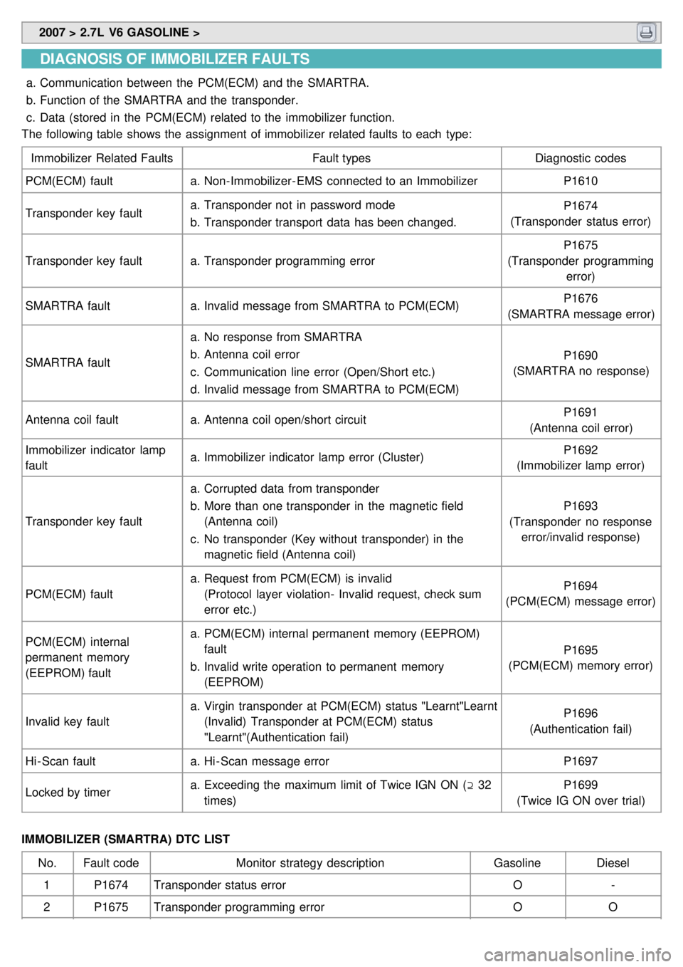
DIAGNOSIS OF IMMOBILIZER FAULTS
a.Communication between the PCM(ECM) and the SMARTRA.
b. Function of the SMARTRA and the transponder.
c. Data (stored in the PCM(ECM) related to the immobilizer function.
The following table shows the assignment of immobilizer related faults to each type:
Immobilizer Related Faults Fault typesDiagnostic codes
PCM(ECM) fault a.Non- Immobilizer- EMS connected to an Immobilizer P1610
Transponder key fault a.
Transponder not in password mode
b. Transponder transport data has been changed. P1674
(Transponder status error)
Transponder key fault a.Transponder programming error P1675
(Transponder programming error)
SMARTRA fault a.Invalid message from SMARTRA to PCM(ECM) P1676
(SMARTRA message error)
SMARTRA fault a.
No response from SMARTRA
b. Antenna coil error
c. Communication line error (Open/Short etc.)
d. Invalid message from SMARTRA to PCM(ECM) P1690
(SMARTRA no response)
Antenna coil fault a.Antenna coil open/short circuit P1691
(Antenna coil error)
Immobilizer indicator lamp
fault a.
Immobilizer indicator lamp error (Cluster) P1692
(Immobilizer lamp error)
Transponder key fault a.
Corrupted data from transponder
b. More than one transponder in the magnetic field
(Antenna coil)
c. No transponder (Key without transponder) in the
magnetic field (Antenna coil) P1693
(Transponder no response error/invalid response)
PCM(ECM) fault a.
Request from PCM(ECM) is invalid
(Protocol layer violation- Invalid request, check sum
error etc.) P1694
(PCM(ECM) message error)
PCM(ECM) internal
permanent memory
(EEPROM) fault a.
PCM(ECM) internal permanent memory (EEPROM)
fault
b. Invalid write operation to permanent memory
(EEPROM) P1695
(PCM(ECM) memory error)
Invalid key fault a.
Virgin transponder at PCM(ECM) status "Learnt"Learnt
(Invalid) Transponder at PCM(ECM) status
"Learnt"(Authentication fail) P1696
(Authentication fail)
Hi - Scan fault a.Hi - Scan message error P1697
Locked by timer a.
Exceeding the maximum limit of Twice IGN ON ( ⊇ 32
times) P1699
(Twice IG ON over trial)
IMMOBILIZER (SMARTRA) DTC LIST No. Fault code Monitor strategy description GasolineDiesel
1 P1674 Transponder status error O-
2 P1675 Transponder programming error OO