Page 480 of 1575
12.Remove the clip (A) and bracket mounting bolt and disconnect the parking brake cable (B) from the carrier
assembly.
13.Remove the rear brake assembly (A).
Tightening torque Nm (kgf.m, lb - ft):
50 ~ 60 (5.0 ~ 6.0, 36 ~ 43)
14.Remove the rear shock absorber (A).
15.After loosening the castle nut and split pin, disconnect the assist arm (A) from the carrier assembly using a SST
(09568- 4A000).
Tightening torque Nm (kgf.m, lb - ft):
90 ~ 100 (9.0 ~ 10.0, 65 ~72)
Page 1211 of 1575

2007 > 2.7L V6 GASOLINE >
DESCRIPTION
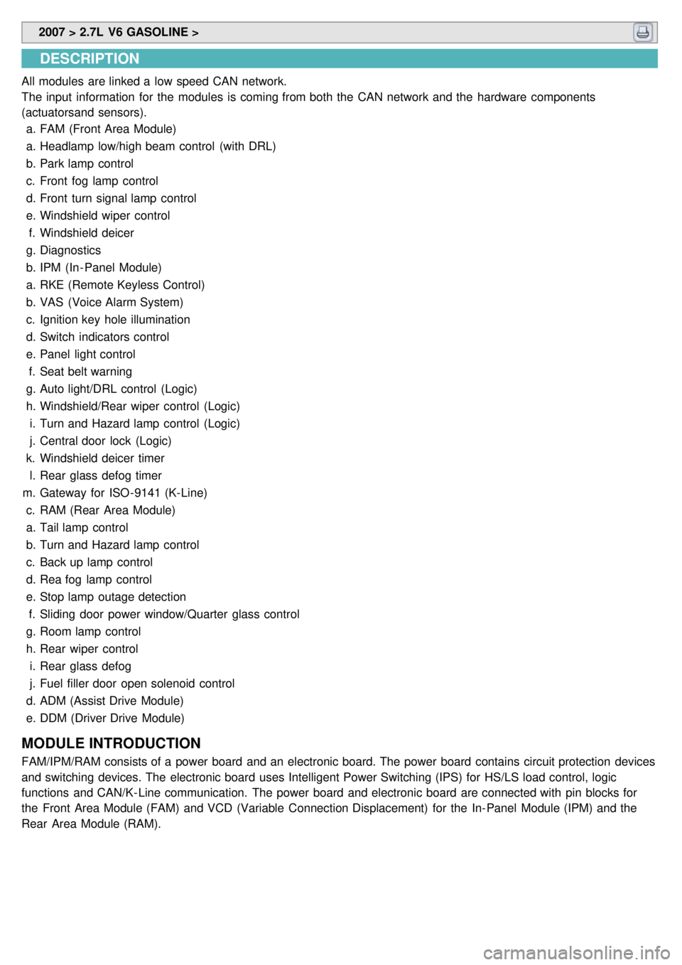
All modules are linked a low speed CAN network.
The input information for the modules is coming from both the CAN network and the hardware components
(actuatorsand sensors).
a. FAM (Front Area Module)
a. Headlamp low/high beam control (with DRL)
b. Park lamp control
c. Front fog lamp control
d. Front turn signal lamp control
e. Windshield wiper control
f. Windshield deicer
g. Diagnostics
b. IPM (In - Panel Module)
a. RKE (Remote Keyless Control)
b. VAS (Voice Alarm System)
c. Ignition key hole illumination
d. Switch indicators control
e. Panel light control
f. Seat belt warning
g. Auto light/DRL control (Logic)
h. Windshield/Rear wiper control (Logic)
i. Turn and Hazard lamp control (Logic)
j. Central door lock (Logic)
k. Windshield deicer timer
l. Rear glass defog timer
m. Gateway for ISO- 9141 (K- Line)
c. RAM (Rear Area Module)
a. Tail lamp control
b. Turn and Hazard lamp control
c. Back up lamp control
d. Rea fog lamp control
e. Stop lamp outage detection
f. Sliding door power window/Quarter glass control
g. Room lamp control
h. Rear wiper control
i. Rear glass defog
j. Fuel filler door open solenoid control
d. ADM (Assist Drive Module)
e. DDM (Driver Drive Module)
MODULE INTRODUCTION
FAM/IPM/RAM consists of a power board and an electronic board. The power board contains circuit protection devices
and switching devices. The electronic board uses Intelligent Power Switching (IPS) for HS/LS load control, logic
functions and CAN/K- Line communication. The power board and electronic board are connected with pin blocks for
the Front Area Module (FAM) and VCD (Variable Connection Displacement) for the In- Panel Module (IPM) and the
Rear Area Module (RAM).
Page 1246 of 1575

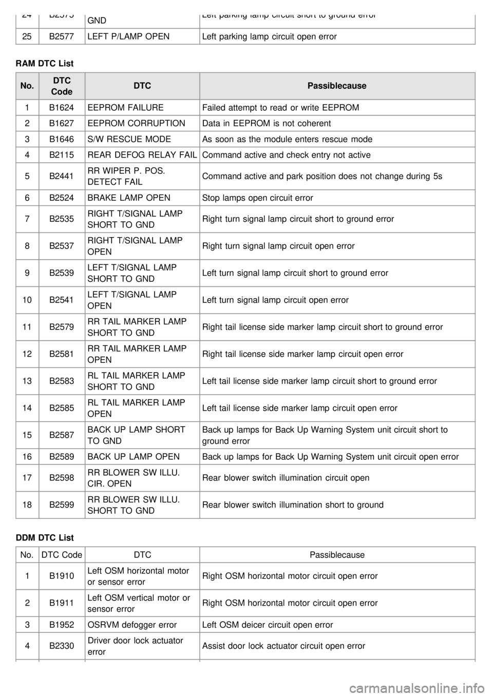
24B2575
GND Left parking lamp circuit short to ground error
25 B2577 LEFT P/LAMP OPEN Left parking lamp circuit open error
RAM DTC List No. DTC
Code DTC
Passiblecause
1 B1624 EEPROM FAILURE Failed attempt to read or write EEPROM
2 B1627 EEPROM CORRUPTION Data in EEPROM is not coherent
3 B1646 S/W RESCUE MODE As soon as the module enters rescue mode
4 B2115 REAR DEFOG RELAY FAIL Command active and check entry not active
5 B2441 RR WIPER P. POS.
DETECT FAIL Command active and park position does not change during 5s
6 B2524 BRAKE LAMP OPEN Stop lamps open circuit error
7 B2535 RIGHT T/SIGNAL LAMP
SHORT TO GND Right turn signal lamp circuit short to ground error
8 B2537 RIGHT T/SIGNAL LAMP
OPEN Right turn signal lamp circuit open error
9 B2539 LEFT T/SIGNAL LAMP
SHORT TO GND Left turn signal lamp circuit short to ground error
10 B2541 LEFT T/SIGNAL LAMP
OPEN Left turn signal lamp circuit open error
11 B2579 RR TAIL MARKER LAMP
SHORT TO GND Right tail license side marker lamp circuit short to ground error
12 B2581 RR TAIL MARKER LAMP
OPEN Right tail license side marker lamp circuit open error
13 B2583 RL TAIL MARKER LAMP
SHORT TO GND Left tail license side marker lamp circuit short to ground error
14 B2585 RL TAIL MARKER LAMP
OPEN Left tail license side marker lamp circuit open error
15 B2587 BACK UP LAMP SHORT
TO GND Back up lamps for Back Up Warning System unit circuit short to
ground error
16 B2589 BACK UP LAMP OPEN Back up lamps for Back Up Warning System unit circuit open error
17 B2598 RR BLOWER SW ILLU.
CIR. OPEN Rear blower switch illumination circuit open
18 B2599 RR BLOWER SW ILLU.
SHORT TO GND Rear blower switch illumination short to ground
DDM DTC List No. DTC Code DTC Passiblecause
1 B1910 Left OSM horizontal motor
or sensor error Right OSM horizontal motor circuit open error
2 B1911 Left OSM vertical motor or
sensor error Right OSM horizontal motor circuit open error
3 B1952 OSRVM defogger error Left OSM deicer circuit open error
4 B2330 Driver door lock actuator
error Assist door lock actuator circuit open error
Page 1531 of 1575
Rear Parking Assist System
Page 1532 of 1575
Rear Parking Assist SystemControl Unit
Page 1540 of 1575
Page 1559 of 1575

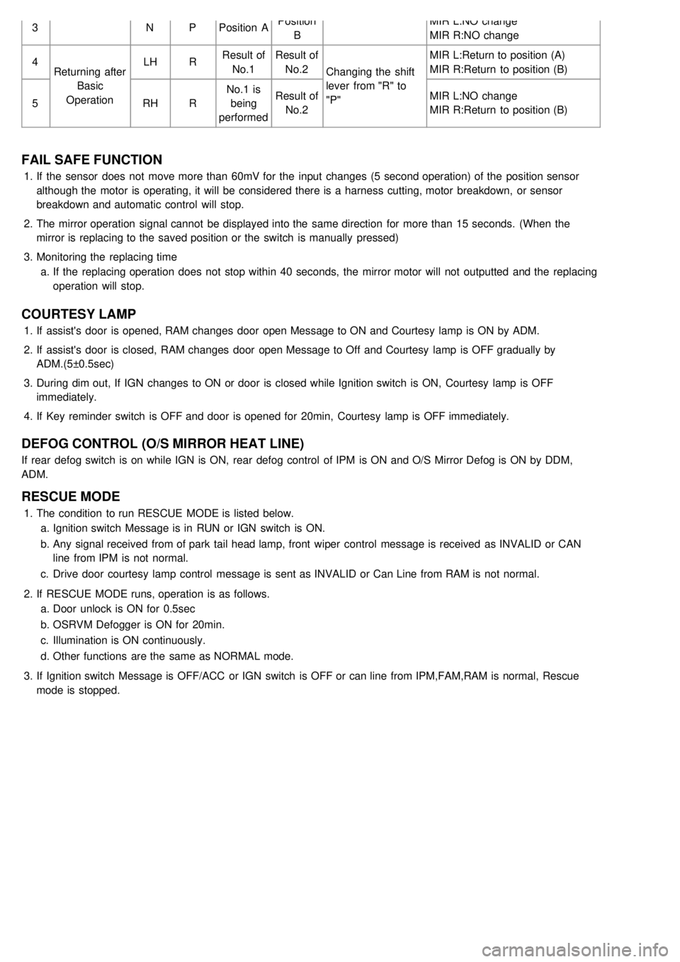
3NPPosition A Position
B MIR L:NO change
MIR R:NO change
4 Returning after
Basic
Operation LH
RResult of
No.1 Result of
No.2 Changing the shift
lever from "R" to
"P" MIR L:Return to position (A)
MIR R:Return to position (B)
5 RHRNo.1 is
being
performed Result of
No.2 MIR L:NO change
MIR R:Return to position (B)
FAIL SAFE FUNCTION
1.
If the sensor does not move more than 60mV for the input changes (5 second operation) of the position sensor
although the motor is operating, it will be considered there is a harness cutting, motor breakdown, or sensor
breakdown and automatic control will stop.
2. The mirror operation signal cannot be displayed into the same direction for more than 15 seconds. (When the
mirror is replacing to the saved position or the switch is manually pressed)
3. Monitoring the replacing time
a. If the replacing operation does not stop within 40 seconds, the mirror motor will not outputted and the replacing
operation will stop.
COURTESY LAMP
1.If assist's door is opened, RAM changes door open Message to ON and Courtesy lamp is ON by ADM.
2. If assist's door is closed, RAM changes door open Message to Off and Courtesy lamp is OFF gradually by
ADM.(5±0.5sec)
3. During dim out, If IGN changes to ON or door is closed while Ignition switch is ON, Courtesy lamp is OFF
immediately.
4. If Key reminder switch is OFF and door is opened for 20min, Courtesy lamp is OFF immediately.
DEFOG CONTROL (O/S MIRROR HEAT LINE)
If rear defog switch is on while IGN is ON, rear defog control of IPM is ON and O/S Mirror Defog is ON by DDM,
ADM.
RESCUE MODE
1.The condition to run RESCUE MODE is listed below.
a. Ignition switch Message is in RUN or IGN switch is ON.
b. Any signal received from of park tail head lamp, front wiper control message is received as INVALID or CAN
line from IPM is not normal.
c. Drive door courtesy lamp control message is sent as INVALID or Can Line from RAM is not normal.
2. If RESCUE MODE runs, operation is as follows.
a. Door unlock is ON for 0.5sec
b. OSRVM Defogger is ON for 20min.
c. Illumination is ON continuously.
d. Other functions are the same as NORMAL mode.
3. If Ignition switch Message is OFF/ACC or IGN switch is OFF or can line from IPM,FAM,RAM is normal, Rescue
mode is stopped.