2007 KIA CARNIVAL engine
[x] Cancel search: enginePage 941 of 1575

be probably an open in the HECU power circuit or an open in the
diagnosis output circuit.b.
Inoperative HECU
c. Inoperative power source circuit
INSPECTION PROCEDURES
CHECK FOR CONTINUITY IN THE DIAGNOSIS LINE
1. Disconnect the connector from the ABS control module.
2. Check for continuity between terminals 11 of the ABS control module connector and 1 of the data link connector.
Is there continuity?
▶ Check the power source of ABS control module.
▶ Repair an open in the wire.
CHECK THE POWER SOURCE OF ABS CONTROL MODULE
1. Disconnect the connector from the ABS control module.
2. Turn the ignition switch ON, measure the voltage between terminal 18 of the ABS control module harness side
connector and body ground.
Specification: approximately B+
Is voltage within specification?
▶ Check for poor ground.
▶ Check the harness or connector between the fuse (10A) in the engine compartment junction block and the ABS
control module.Repair if necessary.
CHECK FOR POOR GROUND
Check for continuity between terminal 5 of the data link connector and ground point.
▶ Replace the ABS control module and recheck.
▶ Repair an open in the wire or poor ground.
Page 942 of 1575

DETECTING CONDITIONTrouble Symptoms Possible Cause
When current flows in the HECU the ABS warning lamp turns from
ON to OFF as the initial check.Therefore if the lamp does not light up,
the cause may be an open in the lamp power supply circuit, a blown
bulb, an open in the both circuits between the ABS warning lamp and
the HECU, and the inoperative HECU. a.
Inoperative ABS warning lamp bulb
b. Blown No.2 fuse (10A) in the engine
compartment junction block
c. Inoperative ABS warning lamp module
d. Inoperative HECU
INSPECTION PROCEDURES
PROBLEM VERIFICATION
Disconnect the connector from the ABS control module and turn the ignition switch ON.
Does the ABS warning lamp light up?
▶ It is normal. Recheck the ABS control module.
▶ Check the power source for the ABS warning lamp.
CHECK THE POWER SOURCE FOR THE ABS WARNING LAMP
1. Disconnect the instrument cluster connector and turn the ignition switch ON.
2. Measure the voltage between terminal 8 of the cluster harness side connector and body ground.
Specification: approximately B+
Is voltage within specification?
▶ Repair bulb or instrument cluster assembly.
▶ Check for blown fuse.
Page 943 of 1575

CHECK FOR BLOWN FUSE
Check continuity of fuse (10A) from the engine compartment junction block.
Is there continuity?
▶ Repair an open in the wire between ABS fuse and 1 of cluster connector.
▶ Replace the blown fuse.
DETECTING CONDITION
Trouble Symptoms Possible Cause
If the HECU detects trouble, it lights the ABS warning lamp while at
the same time prohibiting ABS control. At this time, the HECU
records a DTC in memory.Even though the normal code is output, the
ABS warning lamp remains ON, then the cause may be probably an
open or short in the ABS warning lamp circuit. a.
An open in the wire
b. Inoperative instrument cluster assembly
c. Inoperative ABS warning lamp module
d. Inoperative HECU
INSPECTION PROCEDURES
CHECK DTC OUTPUT.
1. Connect the Scan Tool to the 16P data link connector located behind the driver's side kick panel.
2. Check the DTC output using Scan Tool.
Is DTC output ?
▶ Repair circuit indicated by code output.
▶ Check instrument cluster.
CHECK INSTRUMENT CLUSTER
Disconnect the cluster connector and turn the ignition switch ON.
Does the ABS warning lamp remains ON?
▶ Replace the instrument cluster.
▶ Check for open the wire.
CHECK FOR OPEN IN THE WIRE
Check for continuity in the wire between cluster and ABS control module.
Is there continuity?
▶ Replace the ABS control module and recheck.
▶ Repair an open in the wire between cluster and ABS control module.
BLEEDING OF BRAKE SYSTEM
1. Remove the reservoir cap and fill the brake reservoir with brake fluid.
If there is any brake fluid on any painted surface, wash it off immediately.
Page 967 of 1575

2007 > 2.7L V6 GASOLINE >
description of ESP
Optimum driving safety now has a name : ESP, the Electronic Stability Control.
ESP recognizes critical driving conditions, such as panic reactions in dangerous situations, and stabilizes the vehicle
by wheel- individual braking and engine control intervention with no needfor actuating the brake or the gas pedal.
ESP adds a further function known as Active Yaw Control (AYC) to the ABS, TCS, EBD and ESP functions. Whereas
the ABS/TCS function controls wheel slip during braking and acceleration and, thus, mainly intervenes in the
longitudinal dynamics of the vehicle, active yaw control stabilizes the vehicle about its vertical axis.
This is achieved by wheel individual brake intervention and adaptation of the momentary engine torque with no need
for any action to be taken by the driver.
ESC essentially consists of three assemblies : the sensors, the electronic control unit and the actuators.
Of course, the stability control feature works under all driving and operating conditions. Under certain driving
conditions, the ABS/TCS function can be activated simultaneously with the ESP function in response to a command
by the driver.
In the event of a failure of the stability control function, the basic safety function, ABS, is still maintained.
DESCRIPTION OF ESP CONTROL
ESP system includes ABS/EBD, TCS and AYC (Active yaw control) function.
ABS/EBD function : The ECU changes the active sensor signal (current shift) coming from the four wheel sensors to
the square waveform.By using the input of above signals, the ECU calculates the vehicle speed and the acceleration
& deceleration of the four wheels.And, the ECU judges whether the ABS/EBD should be actuated or not.
TCS function prevents the wheel slip of drive direction by adding the brake pressure and engine torque reduction via
CAN communication.TCS function uses the wheel speed sensor signal to determine the wheel slip as far as ABS
function.
AYC function prevents unstable maneuver of the vehicle. To determine the vehicle maneuver, AYC function uses the
maneuver sensor signals(Yaw Rate Sensor, Lateral Acceleration Sensor, Steering Wheel Angle Sensor).If vehicle
maneuver is unstable (Over Steer or Under Steer), AYC function applies the brake pressure on certain wheel, and
send engine torque reduction signal by CAN.
After the key - on, the ECU continually diagnoses the system failure. (self- diagnosis)If the system failure is detected,
the ECU informs driver of the system failure through the BRAKE/ABS/ESP warning lamp. (fail- safe warning)
Page 1152 of 1575

2007 > 2.7L V6 GASOLINE >
GENERAL TROUBLESHOOTING INFORMATION
BEFORE TROUBLESHOOTING
1. Check applicable fuses in the appropriate fuse/relay box.
2. Check the battery for damage, state of charge, and clean and tight connections.
a.Do not quick- charge a battery unless the battery ground cable has been disconnected, otherwise you will
damage the generator diodes.
b. Do not attempt to crank the engine with the battery ground cable loosely connected or you will severely
damage the wiring.
3. Check the generator belt tension.
HANDLING CONNECTORS
1.Make sure the connectors are clean and have no loose wire terminals.
2. Make sure multiple cavity connectors are packed with grease (except watertight connectors).
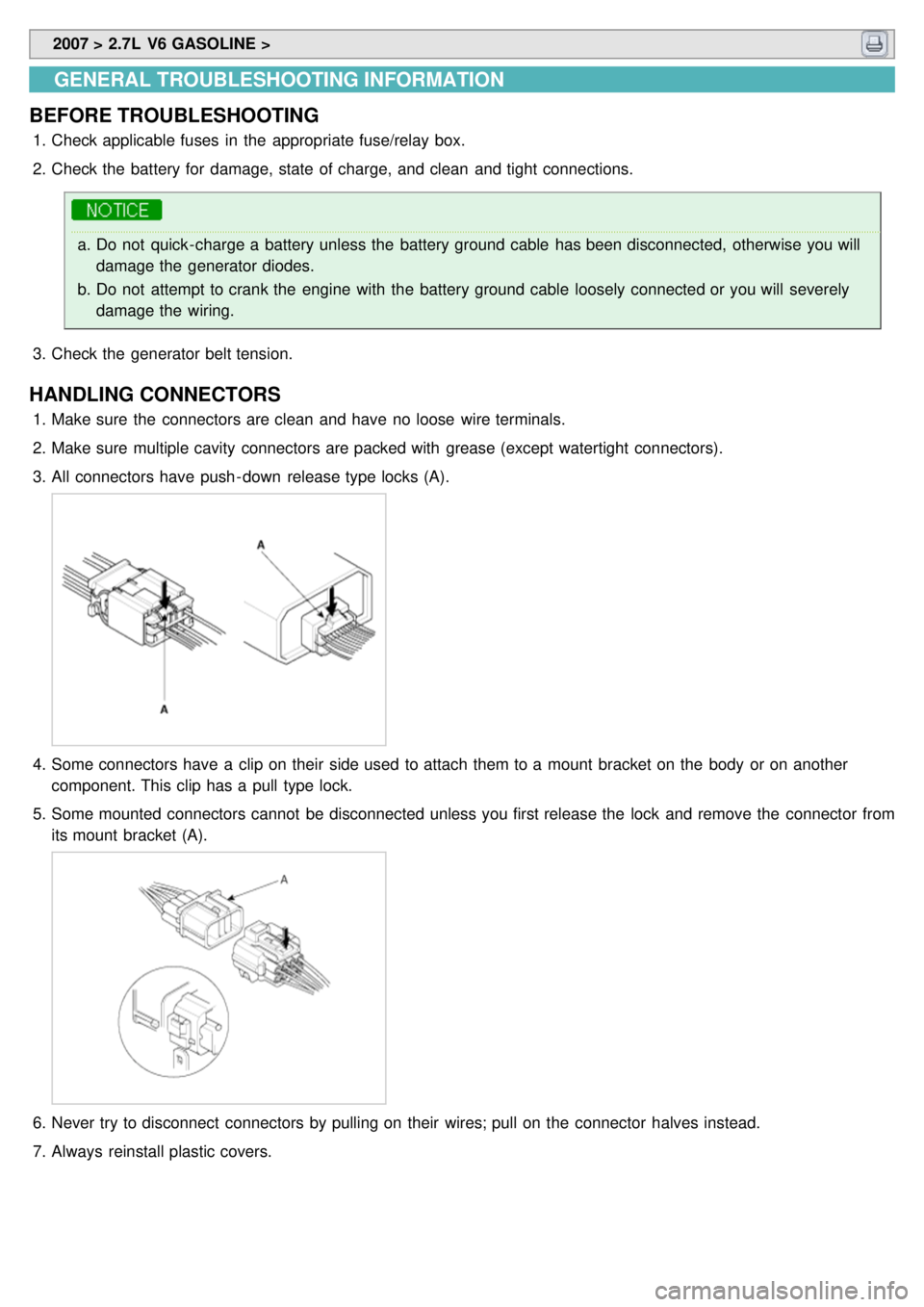
3. All connectors have push - down release type locks (A).
4.Some connectors have a clip on their side used to attach them to a mount bracket on the body or on another
component. This clip has a pull type lock.
5. Some mounted connectors cannot be disconnected unless you first release the lock and remove the connector from
its mount bracket (A).
6.Never try to disconnect connectors by pulling on their wires; pull on the connector halves instead.
7. Always reinstall plastic covers.
Page 1214 of 1575

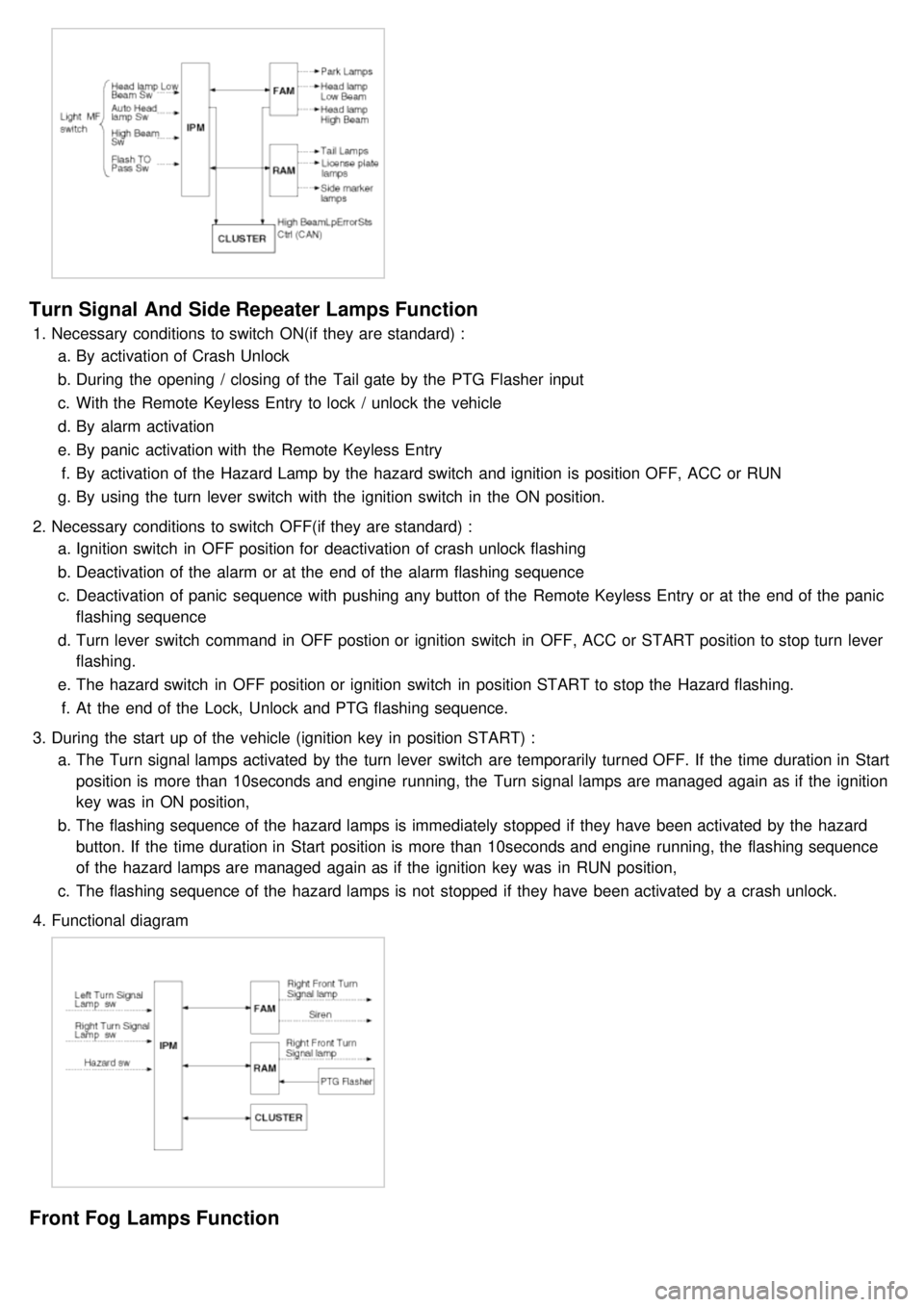
Turn Signal And Side Repeater Lamps Function
1.Necessary conditions to switch ON(if they are standard) :
a. By activation of Crash Unlock
b. During the opening / closing of the Tail gate by the PTG Flasher input
c. With the Remote Keyless Entry to lock / unlock the vehicle
d. By alarm activation
e. By panic activation with the Remote Keyless Entry
f. By activation of the Hazard Lamp by the hazard switch and ignition is position OFF, ACC or RUN
g. By using the turn lever switch with the ignition switch in the ON position.
2. Necessary conditions to switch OFF(if they are standard) :
a. Ignition switch in OFF position for deactivation of crash unlock flashing
b. Deactivation of the alarm or at the end of the alarm flashing sequence
c. Deactivation of panic sequence with pushing any button of the Remote Keyless Entry or at the end of the panic
flashing sequence
d. Turn lever switch command in OFF postion or ignition switch in OFF, ACC or START position to stop turn lever
flashing.
e. The hazard switch in OFF position or ignition switch in position START to stop the Hazard flashing.
f. At the end of the Lock, Unlock and PTG flashing sequence.
3. During the start up of the vehicle (ignition key in position START) :
a. The Turn signal lamps activated by the turn lever switch are temporarily turned OFF. If the time duration in Start
position is more than 10seconds and engine running, the Turn signal lamps are managed again as if the ignition
key was in ON position,
b. The flashing sequence of the hazard lamps is immediately stopped if they have been activated by the hazard
button. If the time duration in Start position is more than 10seconds and engine running, the flashing sequence
of the hazard lamps are managed again as if the ignition key was in RUN position,
c. The flashing sequence of the hazard lamps is not stopped if they have been activated by a crash unlock.
4. Functional diagram
Front Fog Lamps Function
Page 1216 of 1575

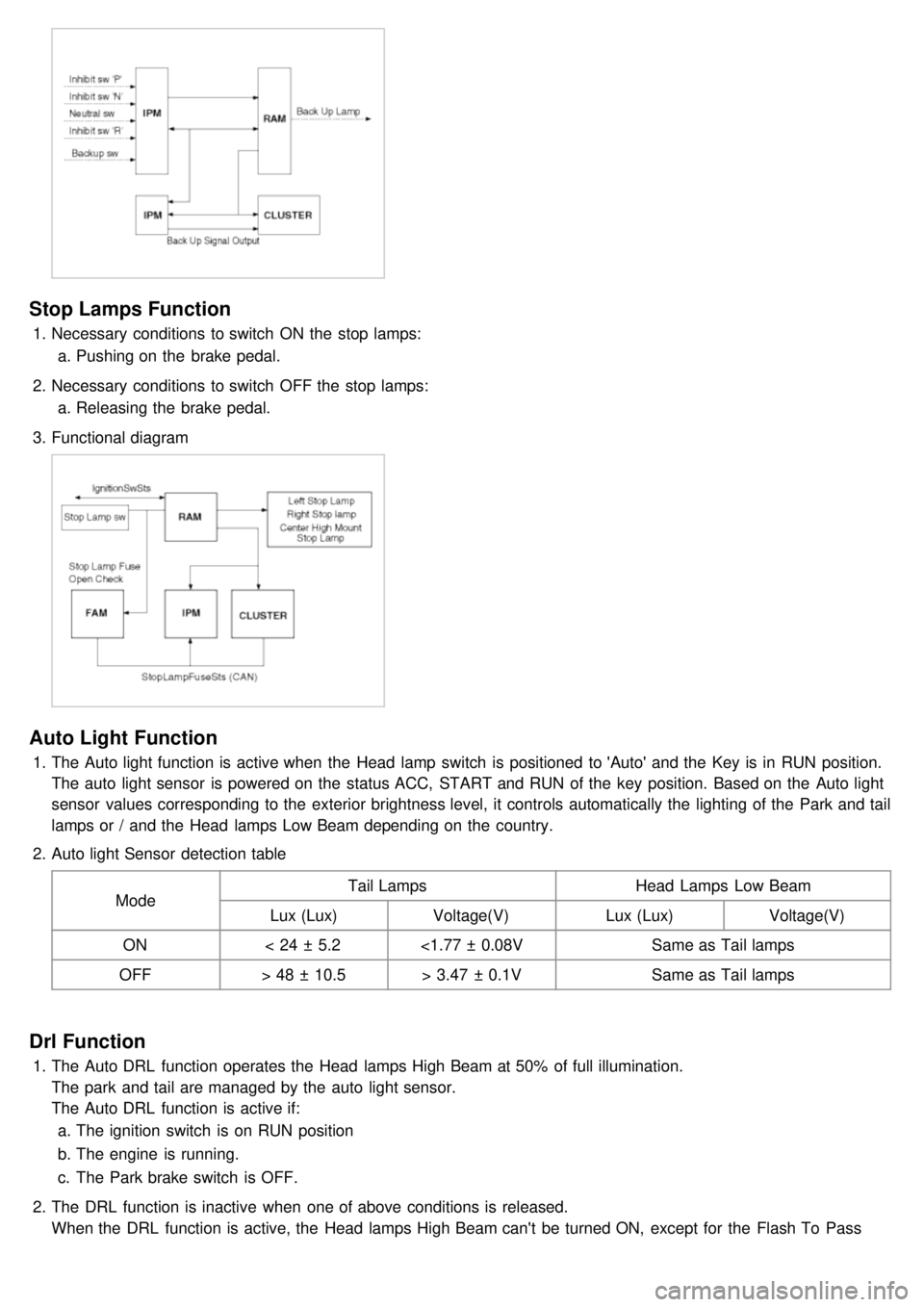
Stop Lamps Function
1.Necessary conditions to switch ON the stop lamps:
a. Pushing on the brake pedal.
2. Necessary conditions to switch OFF the stop lamps:
a. Releasing the brake pedal.
3. Functional diagram
Auto Light Function
1.The Auto light function is active when the Head lamp switch is positioned to 'Auto' and the Key is in RUN position.
The auto light sensor is powered on the status ACC, START and RUN of the key position. Based on the Auto light
sensor values corresponding to the exterior brightness level, it controls automatically the lighting of the Park and tail
lamps or / and the Head lamps Low Beam depending on the country.
2. Auto light Sensor detection table
Mode Tail Lamps
Head Lamps Low Beam
Lux (Lux) Voltage(V) Lux (Lux)Voltage(V)
ON < 24 ± 5.2 <1.77 ± 0.08V Same as Tail lamps
OFF > 48 ± 10.5 > 3.47 ± 0.1V Same as Tail lamps
Drl Function
1.The Auto DRL function operates the Head lamps High Beam at 50% of full illumination.
The park and tail are managed by the auto light sensor.
The Auto DRL function is active if:
a. The ignition switch is on RUN position
b. The engine is running.
c. The Park brake switch is OFF.
2. The DRL function is inactive when one of above conditions is released.
When the DRL function is active, the Head lamps High Beam can't be turned ON, except for the Flash To Pass
activation.
Page 1223 of 1575

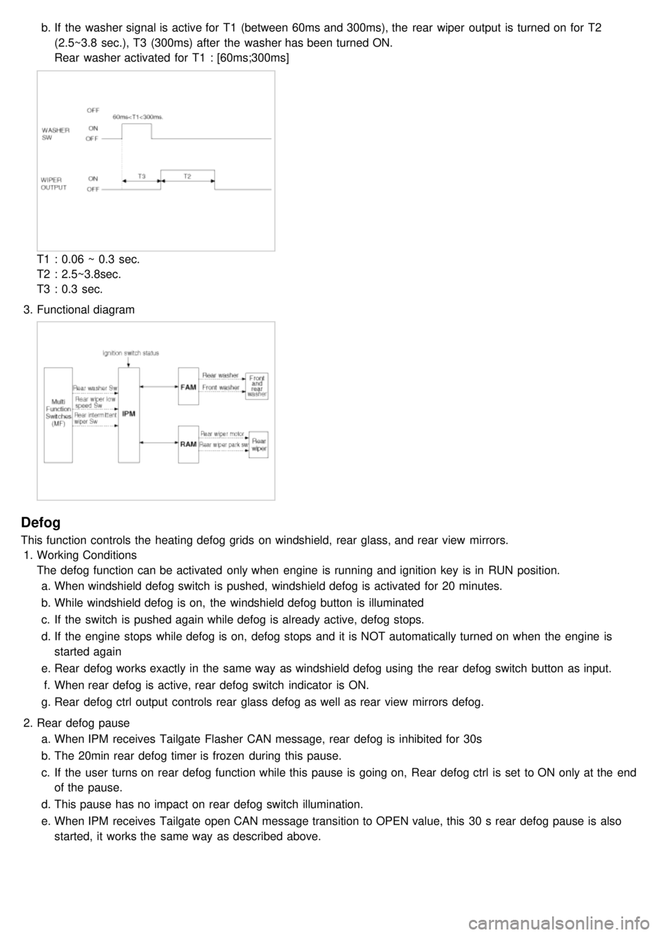
b.If the washer signal is active for T1 (between 60ms and 300ms), the rear wiper output is turned on for T2
(2.5~3.8 sec.), T3 (300ms) after the washer has been turned ON.
Rear washer activated for T1 : [60ms;300ms]
T1 : 0.06 ~ 0.3 sec.
T2 : 2.5~3.8sec.
T3 : 0.3 sec.
3. Functional diagram
Defog
This function controls the heating defog grids on windshield, rear glass, and rear view mirrors.
1. Working Conditions
The defog function can be activated only when engine is running and ignition key is in RUN position.
a. When windshield defog switch is pushed, windshield defog is activated for 20 minutes.
b. While windshield defog is on, the windshield defog button is illuminated
c. If the switch is pushed again while defog is already active, defog stops.
d. If the engine stops while defog is on, defog stops and it is NOT automatically turned on when the engine is
started again
e. Rear defog works exactly in the same way as windshield defog using the rear defog switch button as input.
f. When rear defog is active, rear defog switch indicator is ON.
g. Rear defog ctrl output controls rear glass defog as well as rear view mirrors defog.
2. Rear defog pause
a. When IPM receives Tailgate Flasher CAN message, rear defog is inhibited for 30s
b. The 20min rear defog timer is frozen during this pause.
c. If the user turns on rear defog function while this pause is going on, Rear defog ctrl is set to ON only at the end
of the pause.
d. This pause has no impact on rear defog switch illumination.
e. When IPM receives Tailgate open CAN message transition to OPEN value, this 30 s rear defog pause is also
started, it works the same way as described above.