Page 1228 of 1575

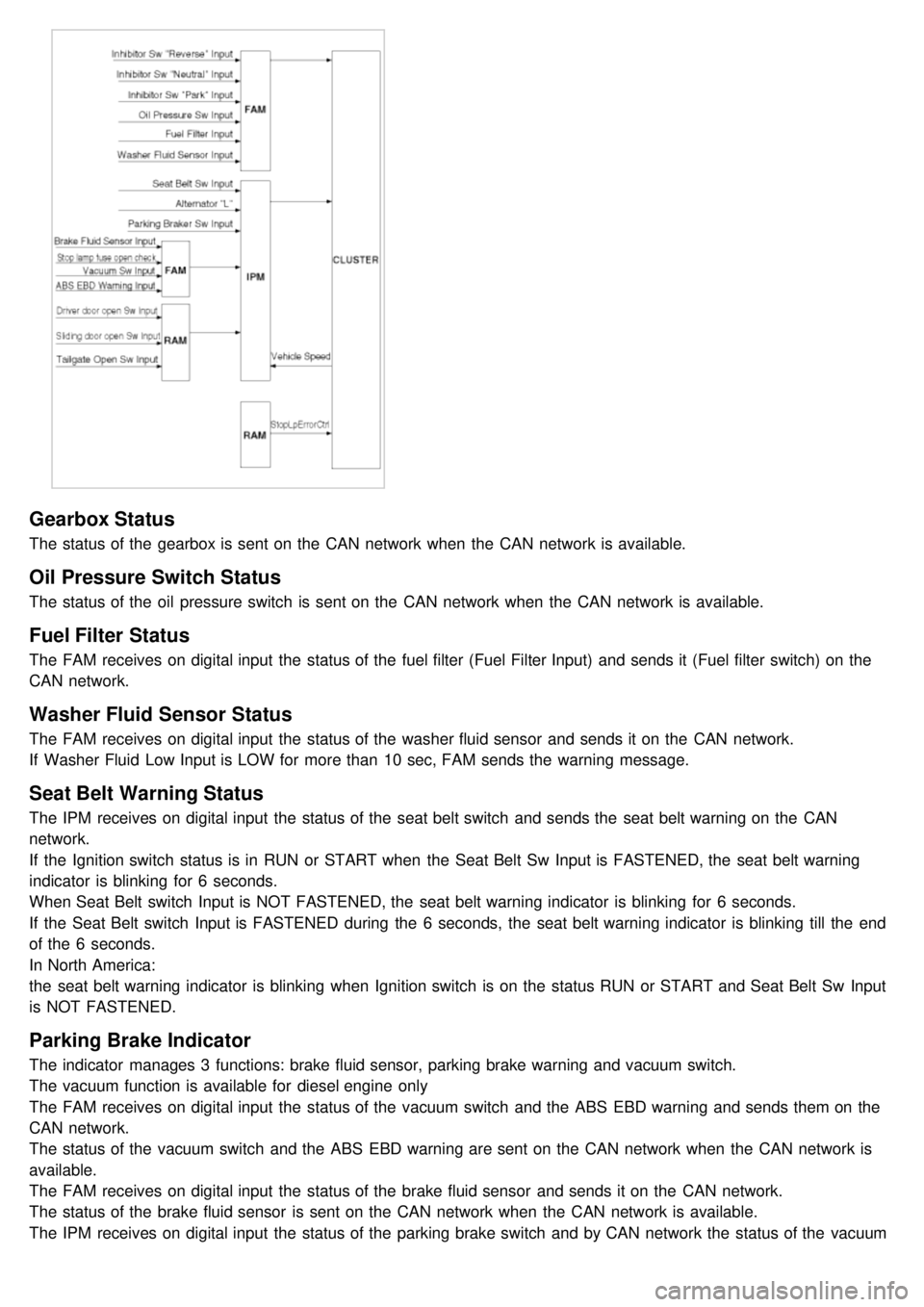
Gearbox Status
The status of the gearbox is sent on the CAN network when the CAN network is available.
Oil Pressure Switch Status
The status of the oil pressure switch is sent on the CAN network when the CAN network is available.
Fuel Filter Status
The FAM receives on digital input the status of the fuel filter (Fuel Filter Input) and sends it (Fuel filter switch) on the
CAN network.
Washer Fluid Sensor Status
The FAM receives on digital input the status of the washer fluid sensor and sends it on the CAN network.
If Washer Fluid Low Input is LOW for more than 10 sec, FAM sends the warning message.
Seat Belt Warning Status
The IPM receives on digital input the status of the seat belt switch and sends the seat belt warning on the CAN
network.
If the Ignition switch status is in RUN or START when the Seat Belt Sw Input is FASTENED, the seat belt warning
indicator is blinking for 6 seconds.
When Seat Belt switch Input is NOT FASTENED, the seat belt warning indicator is blinking for 6 seconds.
If the Seat Belt switch Input is FASTENED during the 6 seconds, the seat belt warning indicator is blinking till the end
of the 6 seconds.
In North America:
the seat belt warning indicator is blinking when Ignition switch is on the status RUN or START and Seat Belt Sw Input
is NOT FASTENED.
Parking Brake Indicator
The indicator manages 3 functions: brake fluid sensor, parking brake warning and vacuum switch.
The vacuum function is available for diesel engine only
The FAM receives on digital input the status of the vacuum switch and the ABS EBD warning and sends them on the
CAN network.
The status of the vacuum switch and the ABS EBD warning are sent on the CAN network when the CAN network is
available.
The FAM receives on digital input the status of the brake fluid sensor and sends it on the CAN network.
The status of the brake fluid sensor is sent on the CAN network when the CAN network is available.
The IPM receives on digital input the status of the parking brake switch and by CAN network the status of the vacuum
switch, the status of the ABS EBD warning, the status of the brake fluid sensor and the speed of the vehicle.
Page 1252 of 1575
4.Installation is the reverse of removal.
FAM (Front Area Module)
1.Disconnect the negative ( - ) battery terminal.
2. Remove the FAM cover from the engine room.
3. Remove the 2 FAM connectors(A) and battery terminal nut(B).
4.Remove the IPM(B) from the splesh shield(C) after loosening the 3 IPM mounting bolts(A) and the IPM mounting
clip.
5.Disconnect the connector from the splesh shield.
6. Installation is the reverse of removal.
RAM (Rear Area Module)
1.Disconnect the negative ( - ) battery terminal.
2. Remove the left luggage side trim
(Refer to the Body group - interior trim)
3. Remove the RAM(A) after loosening the 7 connectors and the 3 RAM mounting bolts(A).
Page 1259 of 1575

2007 > 2.7L V6 GASOLINE >
DESCRIPTION
An optimal seat position set by a driver can be memorized in P/seat unit by memory SW and position SW, which
enables restoration of seat position set by the driver despite seat adjustments.
Furthermore, data is transmitted between P/seat and IPM, DDM, ADM, RAM, FAM, CLUSTER through CAN BUS.
Seat position presets cannot be recalled while driving. An emergency stop function is provided; additional functions are
described below.
1. It conducts manual operation of seat by CAN BUS data transmitted by DDM as well as that of adjustable pedal by
CAN BUS data transmitted by IPM received when operating SW manually.
2. Manual SW behavior when communication stops (back- up behavior)
a. Slide front/rear
b. Recline front/rear
c. Position control of slide motor is possible by manual SW even in case of congestion in CPU or removal of a
fuse for P/seat unit B.
3. 2 memory locations are provided for storing seat, outside mirror, and adjustable pedal presets.
4. The driver seat can be set to slide rearward when the ignition key is removed, and forward when the key is
inserted.
5. 2 additional presets for seat, mirror, and adjustable pedal position can be stored with the RKE transmitter.
OPERATION
MANUAL OPERATION
Manual operation of the driver seat and adjustable pedals is possible provided the transaxle is in 'P' range and the
vehicle speed is 0 MPH. Operation of the manual controls overrides any automatic operation commanded via CAN.
MEMORY OPERATION
1. Pressing the 'M' button on the control panel will place the system into memory storage mode and will result in a
single pulse from the output buzzer.
2. If one of the memory location buttons is pressed and held within 5 seconds of pressing the 'M' button, the output
buzzer will pulse twice to indicate successful storage of seat, mirror, and adjustable pedal positions.
3. The ignition switch must be in the RUN or START position, the vehicle speed must be 0 MPH, and the transaxle
must be in 'P' range to store memory presets.
4. Pressing the 'M' button while recalling a stored preset will halt the preset recall operation.
5. Memory will be cleared if battery is removed.
MEMORY REPLAY OPERATION
1.Pressing one of the memory location buttons will result in the driver seat, outside mirrors, and adjustable pedals
being positioned based on the stored preset data.
2. The ignition switch must be in the RUN position, the transaxle must be in 'P' range, the vehicle speed must be 0
MPH, and the manual functions must not be in operation to recall stored presets.
3. Others
a. Play operation not recorded in the position switch will not be conducted and there will be no buzzer output.
b. If other data is received during preset recall operation, the most recent preset recall signal will take
precedence.
c. If engine is started during preset recall operation, halt preset recall operation, and resume it toward target
position 100ms after Ignition switch is returned to "RUN". However, if the START state lasts over 5 sec., it will
not resume even after returning to RUN.
d. If preset recall order is received during engine start, preset recall operation is inhibited.
e. If input from manual switch for seat and adjust pedal occurs during preset recall operation of seat and adjust
pedal, halt all their preset recall operations.
f. If an error occurs during manual operation of seat and adjust pedal, delete Memory.
Page 1287 of 1575
Relay Box
(Engine Compartment)
Page 1292 of 1575
3.If system of some relay is not operate accurately, replace with a new one and check the system.
REPLACEMENT
FAM (FRONT AREA MODULE)
1. Disconnect the negative ( - ) battery terminal.
2. Remove the FAM cover of engine room.
3. Remove the FAM connectors (2EA) (A) and battery terminal nut (1EA) (B).
4.Remove FAM mounting bolts (3EA) (A) and remove the FAM (B) from splash shield (C).
5.Disconnect the connector from splash shield.
6. Installation is the reverse of removal.
Page 1308 of 1575
Tire wear and tire over or under inflation will increase the indication error.
[MPH]Velocity(MPH) 10
204060
Tolerance (MPH) +1.3
0 +1.7
0 +2.3
0 +3.0
0
Velocity (MPH) 80
100 120 -
Tolerance (MPH) +4.0
0 +5.0
0 +6.0
0 -
[KPH] Velocity(KPH) 20
406080100
Tolerance (KPH) +2.6
0 +2.9
0 +3.5
0 +4.1
0 +5
Velocity (KPH) 120
140160180220
Tolerance (KPH) +6
0 +7
0 +8
0 +9
0 +11
0
TACHOMETER
1. Connect the scan tool to the diagnostic link connector or install a tachometer.
2. With the engine started, compare the readings of the tester with that of the tachometer. Replace the tachometer if
the tolerance is exceeded.
a.Reversing the connections of the tachometer will damage the transistor and diodes inside.
b. When removing or installing the tachometer, be careful not to drop it or subject it to severe shock.
Revolution (rpm) 1,000
2,0003,0004,000Engine
Tolerance (rpm) ±100
±125±150±150Gasoline
±100 ±125±150±150Diesel
Page 1309 of 1575

Tolerance(rpm) 5,000
6,0007,0008,000Engine
Revolution (rpm) ±150
±180±210 -Gasoline
±150 ±150 --Diesel
FUEL GAUGE SENDER
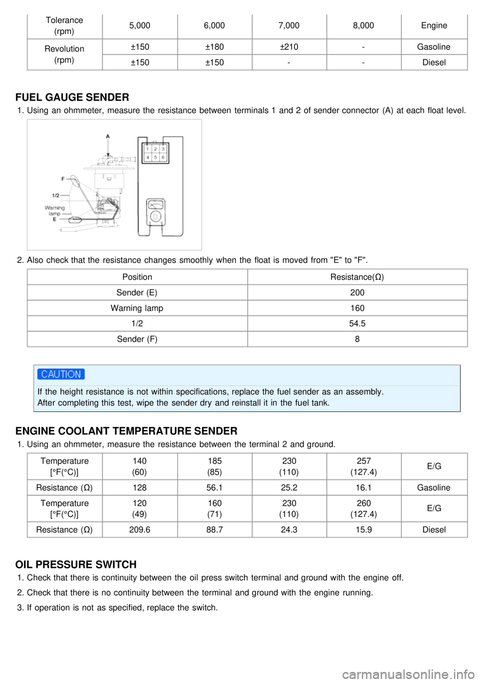
1.Using an ohmmeter, measure the resistance between terminals 1 and 2 of sender connector (A) at each float level.
2.Also check that the resistance changes smoothly when the float is moved from "E" to "F".
Position Resistance(Ω)
Sender (E) 200
Warning lamp 160
1/2 54.5
Sender (F) 8
If the height resistance is not within specifications, replace the fuel sender as an assembly.
After completing this test, wipe the sender dry and reinstall it in the fuel tank.
ENGINE COOLANT TEMPERATURE SENDER
1.Using an ohmmeter, measure the resistance between the terminal 2 and ground.
Temperature[°F(°C)] 140
(60) 185
(85) 230
(110) 257
(127.4) E/G
Resistance (Ω) 12856.1 25.216.1Gasoline
Temperature [°F(°C)] 120
(49) 160
(71) 230
(110) 260
(127.4) E/G
Resistance (Ω) 209.688.724.315.9Diesel
OIL PRESSURE SWITCH
1.Check that there is continuity between the oil press switch terminal and ground with the engine off.
2. Check that there is no continuity between the terminal and ground with the engine running.
3. If operation is not as specified, replace the switch.
Page 1405 of 1575
2007 > 2.7L V6 GASOLINE >
DESCRIPTION
Windshield deicer system prevent windshield wiper from freezing in the winter season. It consists of deicer in the
lower part of windshield, switch and relay. FAM receives an input signal from the deicer switch of IPM through CAN
communication line and then controls relay. Operating condition is the same that of rear window defogger system.
With the engine running and the charging system operating, if the deicer switch is ON, then deicer output is ON for 20
minutes.