2007 KIA CARNIVAL low beam
[x] Cancel search: low beamPage 1218 of 1575
b.When the multifunction switch is not in postion headlamps turned on or autolight
c. 20 mn after the driver door is open
d. 20mn after IGN leaves the positions RUN to ACC or OFF
e. If IPM receives RKE "LOCK" command two times
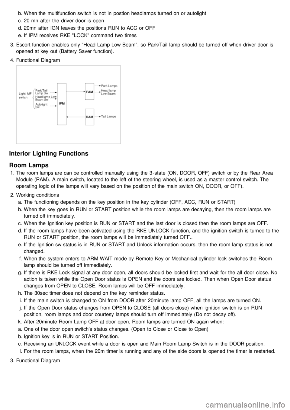
3. Escort function enables only "Head Lamp Low Beam", so Park/Tail lamp should be turned off when driver door is
opened at key out (Battery Saver function).
4. Functional Diagram
Interior Lighting Functions
Room Lamps
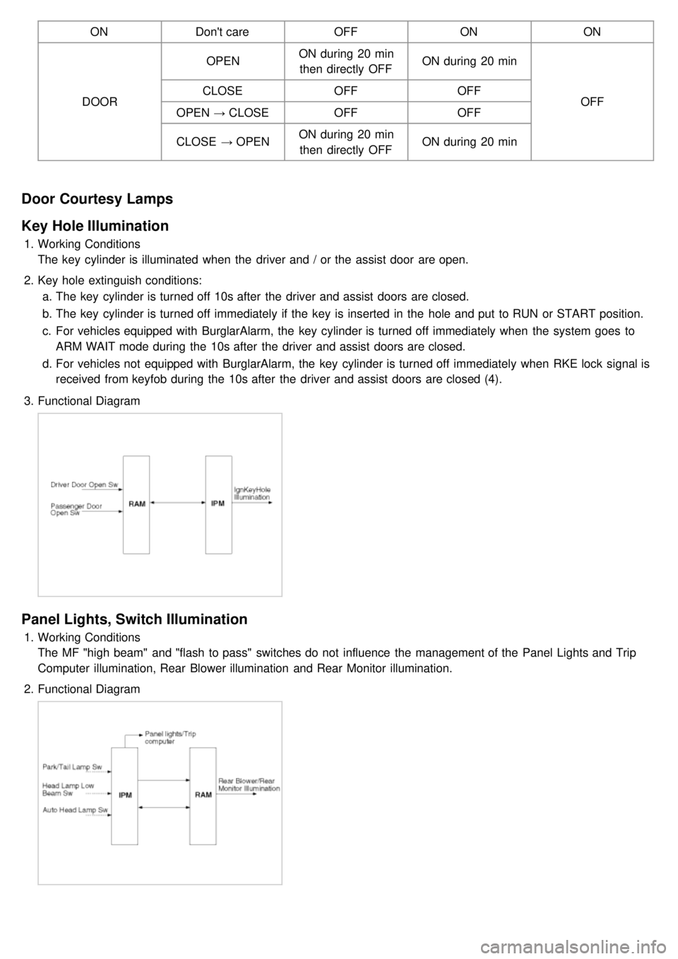
1.The room lamps are can be controlled manually using the 3 - state (ON, DOOR, OFF) switch or by the Rear Area
Module (RAM). A main switch, located to the left of the steering wheel, is used as a master control switch. The
operating logic of the lamps will vary based on the position of the main switch ON, DOOR, or OFF).
2. Working conditions
a. The functioning depends on the key position in the key cylinder (OFF, ACC, RUN or START)
b. When the key goes in RUN or START position while the room lamps are decaying, then the room lamps are
turned off immediately.
c. When the Ignition key position is RUN or START and the last door is closed then the room lamps are OFF.
d. If the room lamps have been activated using the RKE UNLOCK function, and the ignition switch is turned to the
RUN or START position, the room lamps will be immediately turned OFF..
e. If the Ignition sw status is in RUN or START and Unlock information occurs, then the room lamp status is not
changed.
f. When the system enters to ARM WAIT mode by Remote Key or Mechanical cylinder lock switches the Room
lamp should be turned off immediately.
g. If there is RKE Lock signal at any door open, all doors should be locked first and wait for the all door close. No
action is taken while the Open Door status is OPEN and the doors are locked. Then when Open Door status
changes from OPEN to CLOSE, Room lamps will be OFF immediately.
h. The 30sec timer does not depend on the key reminder status.
i. If the main switch is changed to ON from DOOR after 20minute lamp OFF, all the lamps are turned ON.
j. If the Open Door status changes from OPEN to CLOSE (all doors close) when ignition switch is on RUN
position, room lamps and door courtesy lamps should turn off immediately (Do not decay off).
k. After 20minute Room Lamp OFF at door open, Room lamps are turned ON again when:
a. One of the door open switch's status changes. (Open to Close or Close to Open)
b. Ignition key is in RUN or START Position.
c. Receiving an UNLOCK event while a door is open and Main Room Lamp Switch is in the DOOR position.
l. For the room lamps, when the 20m timer is running and any of the side doors is opened the timer is restarted.
3. Functional Diagram
Page 1221 of 1575
ONDon't care OFFONON
DOOR OPEN
ON during 20 min
then directly OFF ON during 20 min
OFF
CLOSE
OFFOFF
OPEN → CLOSE OFF OFF
CLOSE → OPEN ON during 20 min
then directly OFF ON during 20 min
Door Courtesy Lamps
Key Hole Illumination
1.
Working Conditions
The key cylinder is illuminated when the driver and / or the assist door are open.
2. Key hole extinguish conditions:
a. The key cylinder is turned off 10s after the driver and assist doors are closed.
b. The key cylinder is turned off immediately if the key is inserted in the hole and put to RUN or START position.
c. For vehicles equipped with BurglarAlarm, the key cylinder is turned off immediately when the system goes to
ARM WAIT mode during the 10s after the driver and assist doors are closed.
d. For vehicles not equipped with BurglarAlarm, the key cylinder is turned off immediately when RKE lock signal is
received from keyfob during the 10s after the driver and assist doors are closed (4).
3. Functional Diagram
Panel Lights, Switch Illumination
1.Working Conditions
The MF "high beam" and "flash to pass" switches do not influence the management of the Panel Lights and Trip
Computer illumination, Rear Blower illumination and Rear Monitor illumination.
2. Functional Diagram
Page 1227 of 1575
Easy Access
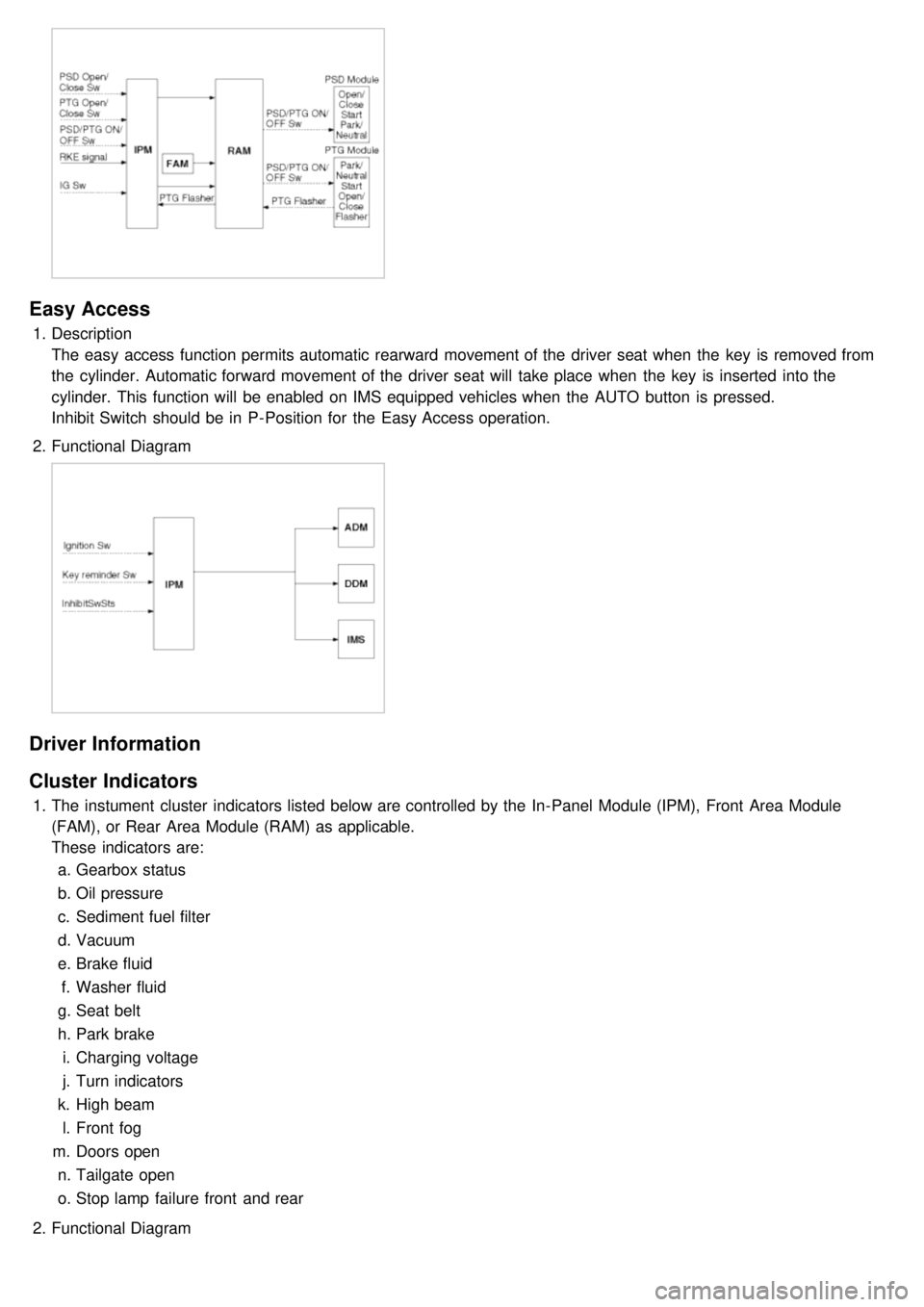
1.Description
The easy access function permits automatic rearward movement of the driver seat when the key is removed from
the cylinder. Automatic forward movement of the driver seat will take place when the key is inserted into the
cylinder. This function will be enabled on IMS equipped vehicles when the AUTO button is pressed.
Inhibit Switch should be in P- Position for the Easy Access operation.
2. Functional Diagram
Driver Information
Cluster Indicators
1.The instument cluster indicators listed below are controlled by the In- Panel Module (IPM), Front Area Module
(FAM), or Rear Area Module (RAM) as applicable.
These indicators are:
a. Gearbox status
b. Oil pressure
c. Sediment fuel filter
d. Vacuum
e. Brake fluid
f. Washer fluid
g. Seat belt
h. Park brake
i. Charging voltage
j. Turn indicators
k. High beam
l. Front fog
m. Doors open
n. Tailgate open
o. Stop lamp failure front and rear
2. Functional Diagram
Page 1229 of 1575
switch, the status of the ABS EBD warning, the status of the brake fluid sensor and the speed of the vehicle.
The IPM sends the park brake indicator control on the CAN network.
The indicator is lighted if the vacuum switch or ABS EBD warning are on or brake fluid sensor is low or park brake
switch is on.
If the speed of the vehicle is over 10 km/h and ignition switch is on the status RUN the park brake indicator control is
blinking at 50% duty in 0.6 second if Parking Brake switch Input is active. In this case Vacuum switch, ABS EBD
warning and Brake Fluid sensor are ignored.
The park brake indicator is blinking on the same time that the chime is ringing. If a CAN signal among Vacuum switch,
EBD warning or Brake Fluid Sens switch is INVALID, out of range or not received this CAN signal is considered to be
OFF.
If VehicleSpeed CAN signal is INVALID or not received, it is considered to be 0 kph.
Charging Voltage Control
The IPM receives on analog input the voltage of generator and sends a warning.
When the voltage of generator L pass strictly above 10V, the state of the CAN variable.
Turn Indicators Status
The status of the turn indicators are sent on the CAN network when the CAN network is available.
High Beam Status
The status of the high beam is sent on the CAN network when the CAN network is available.
Front Fog Lamp Status
The status of the front fog lamp (lightning and state of the bulbs) is sent on the CAN network when the CAN network
is available.
Doors Open Warning
The RAM receives on digital input the status of the driver door open switch and sends it on the CAN network.
The RAM receives on digital input the status of the passenger door open switch and sends it on the CAN network.
The RAM receives on digital input the status of the left sliding door open switch and sends it on the CAN network.
The RAM receives on digital input the status of the right sliding door open switch and sends it on the CAN network.
When vehicle speed is under 10 kph, with ignition key not inserted and any door OPEN, DoorsOpenWngCtrl stays ON
for 20 min and then is turned OFF.
Tailgate Open Switch Status
When vehicle speed is under 10 kph, ignition key is inserted and Tailgate open switch is OPEN, Tailgate Open
warning stays ON forever (IPM can enter sleep mode).
When vehicle speed is under 10 kph, with ignition key not inserted and lgate open switch is OPEN, Tailgate Open
warning stays ON for 20 min and then is turned OFF.
Chime Control
1.The chime warns the driver that a problem is occurred.
These warning are:
a. Seat belt
b. Parking on
c. Over speed
d. Key reminder
e. Light Warning
f. Doors Open
g. Tailgate open warning
2. Chime sound priority:
a. 1st : Seatbelt warning
b. 2nd : Overspeed warning
c. 3rd : Door open warning
d. 4th : T/Gate open warning
e. 5th : Key operated warning
f. 6th : Parking Brake warning
Page 1236 of 1575
Battery Removal
a.If the battery is removed with the system in the ARM state, the system will be placed into the ARM state upon
battery reconnect.
b. The ALARM state will be re- activated if the battery is disconnected, then reconnected, with the system in an
ALARM state.
c. If the battery is disconnected and reconnected with the system in AFTER ALARM state, the alarm will be re-
activated.
d. The system will enter DISARM mode if the battery is disconnected during the ALARM WAIT state.
Panic
a.If RKE PANIC signal is received, Siren output and hazard lamp operate for 27 seconds and the system return to
the previous state as soon as the PANIC function finishes.
b. The PANIC function will be stopped if any RKE signal is received during PANIC activation..
c. If Key reminder switch is ON during PANIC function is operating, PANIC is stopped immediately.
d. If the system goes to ALARM mode during PANIC function is operating, PANIC is stopped immediately and then
ALARM function should be activated.
e. During ALARM state;
If RKE PANIC signal is received, ALARM mode is maintained and PANIC function should be ignored. ALARM has
higher priority than PANIC function.
f. During AFTER_ALARM state;
If RKE PANIC signal is received, AFTR_ALARM mode is maintained and PANIC function should be activated.
Safe & Rescue Mode
The goal of those modes is to be able to cope with failures that may happen on some of the most critical
functionalities (for the driver security) of the system.
Safe Mode
The safe mode is entered in case of system problems such as:
a. Incoherent inputs on monitored signals. In this case, safe mode is the debouncing time before the inputs are
considered INVALID. Note that today, we have no way to detect if the rain/light sensor is in working operation or
not. It means that a driver action will be required in case of failure of this sensor;
b. Loss of the CAN frame containing the monitored signal:
c. Loss of the CAN network: CAN goes to BUS OFF state, safe mode is the time necessary for detecting the BUS
OFF state.
In all cases, the action in safe mode is to maintain the previous state of the system (for lighting and wiping). The list of
monitored signals is the same as in rescue mode
Exiting Safe Mode
The software safe mode is exited and the module goes back to the normal mode when: a. On IPM, hardware inputs return to a coherent state;
b. The lost CAN signal comes back while timeout has not elapsed;
c. The CAN network returns to a normal state without reaching BUS OFF state.
Software safe mode is also exited when the software rescue mode is entered (problem does not disappear).
Hardware safe mode is exited and the module goes back to normal mode if the internal problem disappears (watchdog
is properly triggered again). If the problem stays, hardware safe mode is exited to enter hardware rescue mode.
Rescue Modes
The rescue mode consists in activating some safety functions when IGN2 = ON: a. Switch on the low beams (FAM), park lamps (FAM), tail lamps (RAM) and cluster backlighting (IPM);
b. Unlock of all the doors when the rescue mode is entered with IGN2 = ON
c. Front wipers do not need to be turned on by software in rescue mode because wipers can be turned on by
manually setting the MF switch to low speed. The FAM software must keep the same state as before entering the
rescue mode.
d. When IGN2 = OFF, low beams, park/tail lamps and cluster backlighting are turned off.
Entering Rescue Modes
Page 1240 of 1575
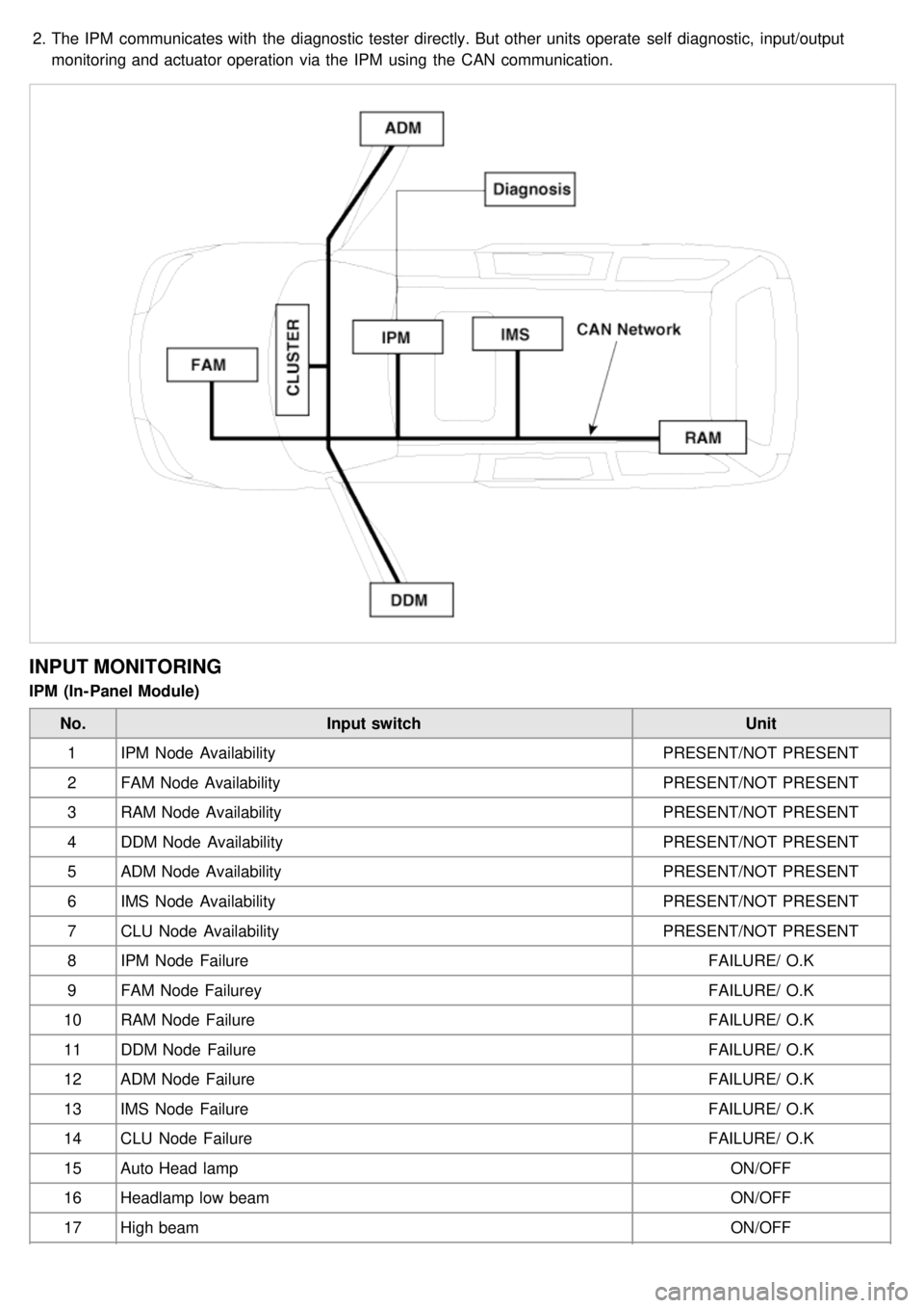
2.The IPM communicates with the diagnostic tester directly. But other units operate self diagnostic, input/output
monitoring and actuator operation via the IPM using the CAN communication.
INPUT MONITORING
IPM (In- Panel Module)
No. Input switch Unit
1 IPM Node Availability PRESENT/NOT PRESENT
2 FAM Node Availability PRESENT/NOT PRESENT
3 RAM Node Availability PRESENT/NOT PRESENT
4 DDM Node Availability PRESENT/NOT PRESENT
5 ADM Node Availability PRESENT/NOT PRESENT
6 IMS Node Availability PRESENT/NOT PRESENT
7 CLU Node Availability PRESENT/NOT PRESENT
8 IPM Node Failure FAILURE/ O.K
9 FAM Node Failurey FAILURE/ O.K
10 RAM Node Failure FAILURE/ O.K
11 DDM Node Failure FAILURE/ O.K
12 ADM Node Failure FAILURE/ O.K
13 IMS Node Failure FAILURE/ O.K
14 CLU Node Failure FAILURE/ O.K
15 Auto Head lamp ON/OFF
16 Headlamp low beam ON/OFF
17 High beam ON/OFF
Page 1434 of 1575
2007 > 2.7L V6 GASOLINE >
DESCRIPTION
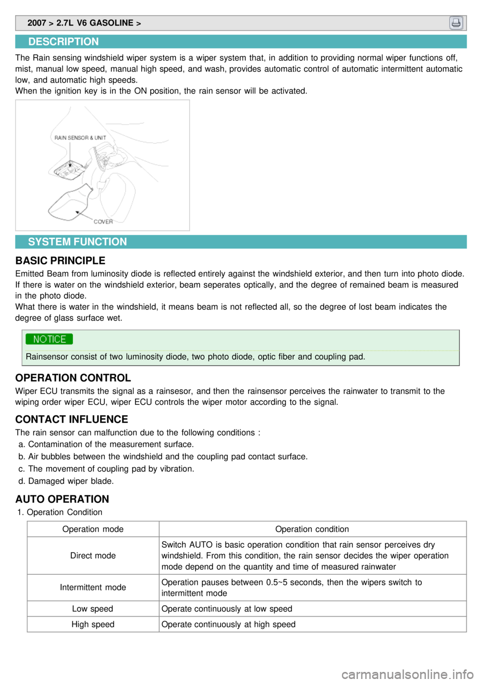
The Rain sensing windshield wiper system is a wiper system that, in addition to providing normal wiper functions off,
mist, manual low speed, manual high speed, and wash, provides automatic control of automatic intermittent automatic
low, and automatic high speeds.
When the ignition key is in the ON position, the rain sensor will be activated.
SYSTEM FUNCTION
BASIC PRINCIPLE
Emitted Beam from luminosity diode is reflected entirely against the windshield exterior, and then turn into photo diode.
If there is water on the windshield exterior, beam seperates optically, and the degree of remained beam is measured
in the photo diode.
What there is water in the windshield, it means beam is not reflected all, so the degree of lost beam indicates the
degree of glass surface wet.
Rainsensor consist of two luminosity diode, two photo diode, optic fiber and coupling pad.
OPERATION CONTROL
Wiper ECU transmits the signal as a rainsesor, and then the rainsensor perceives the rainwater to transmit to the
wiping order wiper ECU, wiper ECU controls the wiper motor according to the signal.
CONTACT INFLUENCE
The rain sensor can malfunction due to the following conditions : a. Contamination of the measurement surface.
b. Air bubbles between the windshield and the coupling pad contact surface.
c. The movement of coupling pad by vibration.
d. Damaged wiper blade.
AUTO OPERATION
1.Operation Condition
Operation mode Operation condition
Direct mode Switch AUTO is basic operation condition that rain sensor perceives dry
windshield. From this condition, the rain sensor decides the wiper operation
mode depend on the quantity and time of measured rainwater
Intermittent mode Operation pauses between 0.5~5 seconds, then the wipers switch to
intermittent mode
Low speed Operate continuously at low speed
High speed Operate continuously at high speed
Page 1469 of 1575
2007 > 2.7L V6 GASOLINE >
REPLACEMENT
1.Disconnect the negative ( - ) battery terminal.
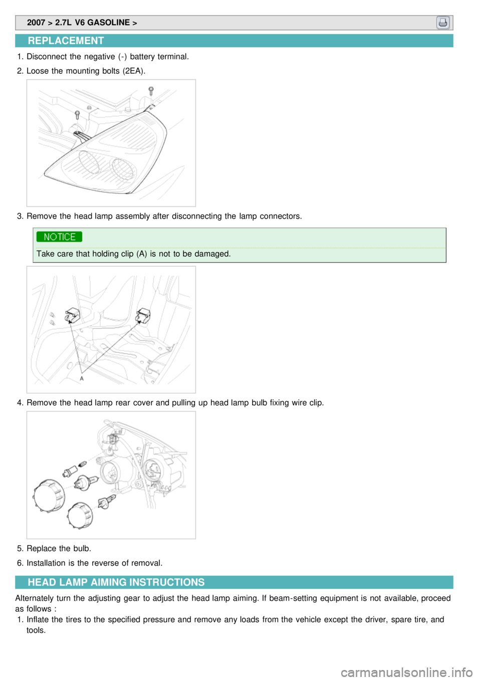
2. Loose the mounting bolts (2EA).
3.Remove the head lamp assembly after disconnecting the lamp connectors.
Take care that holding clip (A) is not to be damaged.
4.Remove the head lamp rear cover and pulling up head lamp bulb fixing wire clip.
5.Replace the bulb.
6. Installation is the reverse of removal.
HEAD LAMP AIMING INSTRUCTIONS
Alternately turn the adjusting gear to adjust the head lamp aiming. If beam- setting equipment is not available, proceed
as follows :
1. Inflate the tires to the specified pressure and remove any loads from the vehicle except the driver, spare tire, and
tools.