Page 224 of 1575

during testing. An example would be if a problem appears only when the vehicle is cold but has not appeared when
warm. In this case, the technician should thoroughly make out a "CUSTOMER PROBLEM ANALYSIS SHEET" and
recreate (simulate) the environment and condition which occurred when the vehicle was having the issue.1. Clear Diagnostic Trouble Code (DTC).
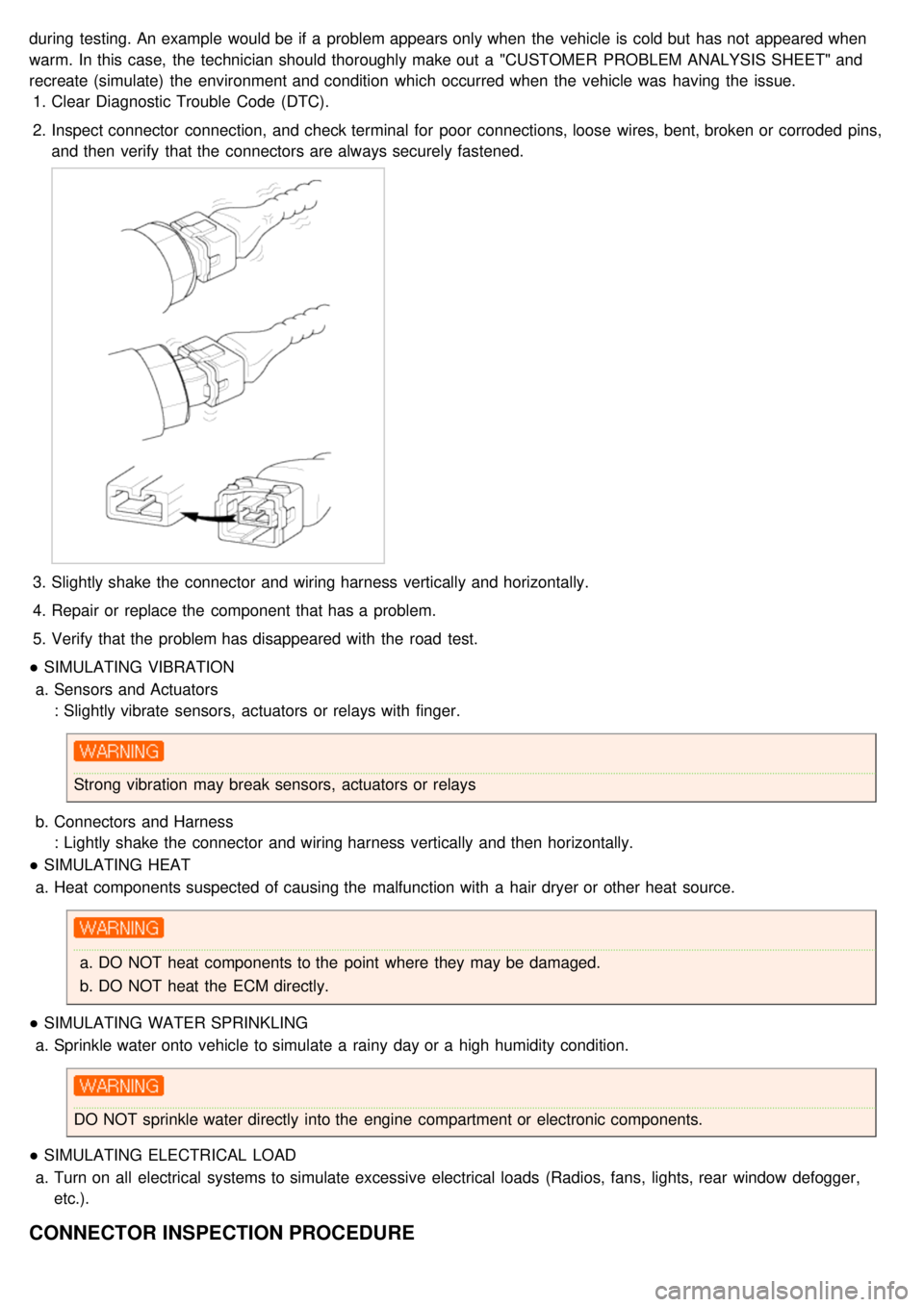
2. Inspect connector connection, and check terminal for poor connections, loose wires, bent, broken or corroded pins,
and then verify that the connectors are always securely fastened.
3.Slightly shake the connector and wiring harness vertically and horizontally.
4. Repair or replace the component that has a problem.
5. Verify that the problem has disappeared with the road test.
● SIMULATING VIBRATION
a. Sensors and Actuators
: Slightly vibrate sensors, actuators or relays with finger.
Strong vibration may break sensors, actuators or relays
b. Connectors and Harness
: Lightly shake the connector and wiring harness vertically and then horizontally.
● SIMULATING HEAT
a. Heat components suspected of causing the malfunction with a hair dryer or other heat source.
a.DO NOT heat components to the point where they may be damaged.
b. DO NOT heat the ECM directly.
● SIMULATING WATER SPRINKLING
a. Sprinkle water onto vehicle to simulate a rainy day or a high humidity condition.
DO NOT sprinkle water directly into the engine compartment or electronic components.
● SIMULATING ELECTRICAL LOAD
a. Turn on all electrical systems to simulate excessive electrical loads (Radios, fans, lights, rear window defogger,
etc.).
CONNECTOR INSPECTION PROCEDURE
Page 239 of 1575

2007 > 2.7L V6 GASOLINE >
DESCRIPTION
1.Engine is hard to start or does not start at all.
2. Unstable idle.
3. Poor driveability
If any of the above conditions are noted, first perform a routine diagnosis that includes basic engine checks (ignition
system malfunction, incorrect engine adjustment, etc.). Then, inspect the Gasoline Engine Control system components
with the HI- SCAN (Pro).
a. Before removing or installing any part, read the diagnostic trouble codes and then disconnect the battery
negative ( - ) terminal.
b. Before disconnecting the cable from battery terminal, turn the ignition switch to OFF. Removal or connection
of the battery cable during engine operation or while the ignition switch is ON could cause damage to the
ECM.
c. The control harnesses between the ECM and heated oxygen sensor are shielded with the shielded ground
wires to the body in order to prevent the influence of ignition noises and radio interference. When the shielded
wire is faulty, the control harness must be replaced.
d. When checking the generator for the charging state, do not disconnect the battery '+' terminal to prevent the
ECM from damage due to the voltage.
e. When charging the battery with the external charger, disconnect the vehicle side battery terminals to prevent
damage to the ECM.
Malfunction Indicator Lamp (MIL)
Faults with the following items will illuminate the MIL.
a. Catalyst
b. Fuel system
c. Mass Air Flow Sensor (MAFS)
d. Intake Air Temperature Sensor (IATS)
e. Engine Coolant Temperature Sensor (ECTS)
f. Throttle Position Sensor (TPS)
g. Upstream Oxygen Sensor
h. Upstream Oxygen Sensor Heater
i. Downstream Oxygen Sensor
j. Downstream Oxygen Sensor Heater
k. Injector
l. Misfire
m. Crankshaft Position Sensor (CKPS)
n. Camshaft Position Sensor (CMPS)
o. Evaporative Emission Control System
p. Vehicle Speed Sensor (VSS)
q. Idle Speed Control Actuator (ISCA)
r. Power Supply
s. ECM/ PCM
t. MT/AT Encoding
u. Acceleration Sensor
v. MIL- on Request Signal
w. Power Stage
Refer to "INSPECTION CHART FOR DIAGNOSTIC TROUBLE CODES (DTC)" for more information.
Page 1075 of 1575
9.Installation is the reverse of removal.
CRASH PAD REPLACEMENT
a.When prying with a flat- tipped screwdriver, wrap itwith protective tape, and apply protective tapearound the
related parts, to prevent damage.
b. Put on gloves to protect your hands.
1. Remove the following items.
a. Front seat.
b. Cluster facia panel, cluster.
c. Audio assembly.
d. Glove box.
e. Side cover, center under cover.
f. Front pillar trim.
2. Remove the photo sensor (C), speaker connector (B).
3. Disconnect the passenger`s air bag connector (A).
Loosen the bolt and nut, then remove the crash pad (D).
4. Installation is the reverse of removal.
a.Make sure the crash pad fits onto the guide pins correctly.
b. Before tightening the bolts, make sure the crash pad wire harnesses are not pinched.
c. Make sure the connectors are plugged in properly, and the antenna lead is connected properly.
d. Enter the anti- theft code for the radio, then enter.
[LHD]
Page 1078 of 1575
d.Enter the anti- theft code for the radio, then enter the customer`s radio station presets.
Page 1159 of 1575
2007 > 2.7L V6 GASOLINE >
CUSTOMER COMPLAINT ANALYSIS CHECK SHEET
TROUBLESHOOTING
There are six areas where a problem can occur: wiring harness, the radio, the cassette tape deck, the CD player, and
speaker. Troubleshooting enables you to confine the problem to a particular area.
Page 1170 of 1575

2007 > 2.7L V6 GASOLINE >
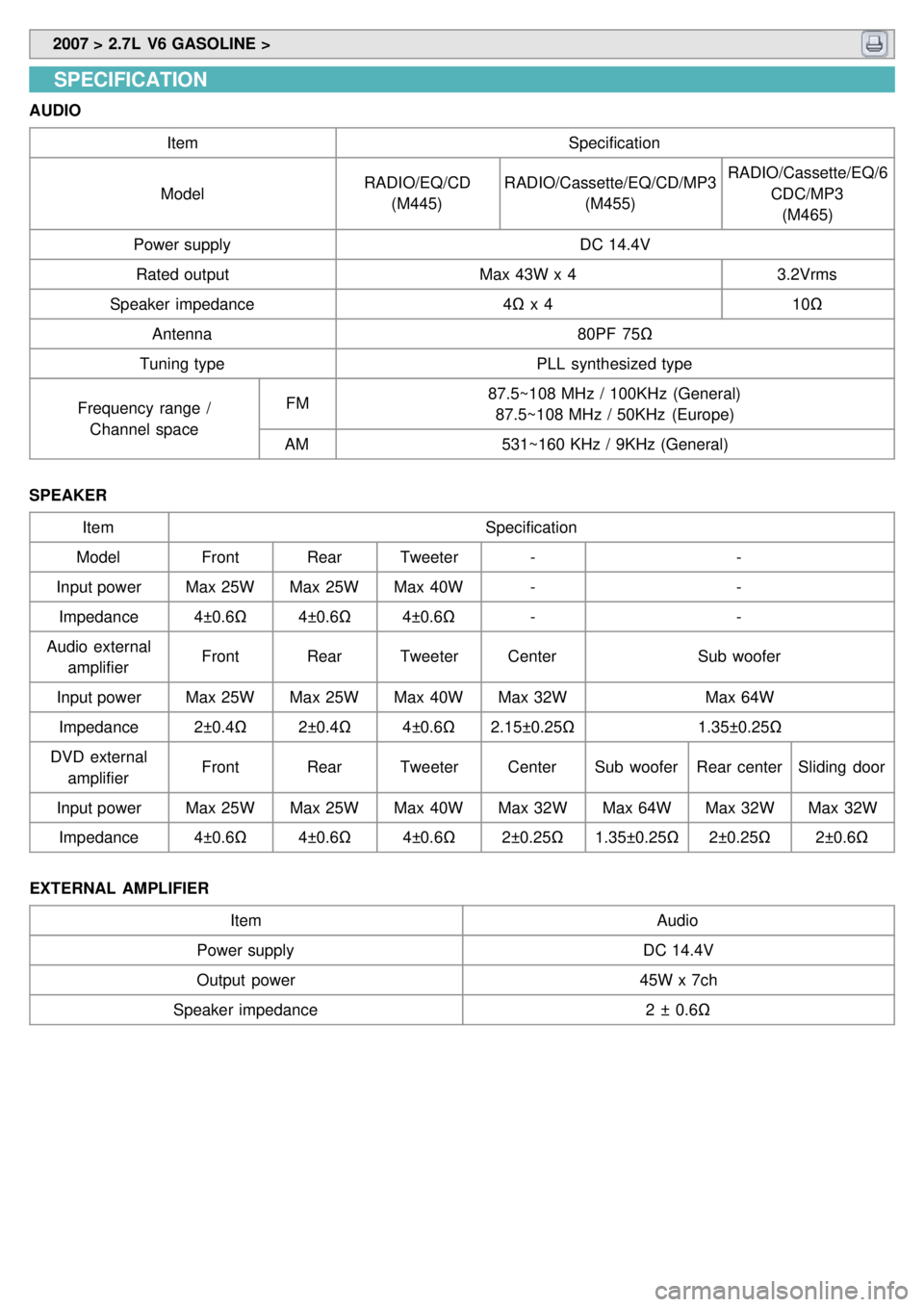
SPECIFICATION
AUDIO
Item Specification
Model RADIO/EQ/CD
(M445) RADIO/Cassette/EQ/CD/MP3
(M455) RADIO/Cassette/EQ/6
CDC/MP3(M465)
Power supply DC 14.4V
Rated output Max 43W x 43.2Vrms
Speaker impedance 4Ω x 4 10Ω
Antenna 80PF 75Ω
Tuning type PLL synthesized type
Frequency range / Channel space FM
87.5~108 MHz / 100KHz (General)
87.5~108 MHz / 50KHz (Europe)
AM 531~160 KHz / 9KHz (General)
SPEAKER Item Specification
Model FrontRearTweeter - -
Input power Max 25WMax 25WMax 40W - -
Impedance 4±0.6Ω4±0.6Ω4±0.6Ω - -
Audio external amplifier Front
RearTweeter Center Sub woofer
Input power Max 25WMax 25WMax 40WMax 32W Max 64W
Impedance 2±0.4Ω2±0.4Ω4±0.6Ω2.15±0.25Ω 1.35±0.25Ω
DVD external amplifier Front
RearTweeter CenterSub woofer Rear centerSliding door
Input power Max 25WMax 25WMax 40WMax 32WMax 64WMax 32WMax 32W
Impedance 4±0.6Ω4±0.6Ω4±0.6Ω2±0.25Ω1.35±0.25Ω 2±0.25Ω2±0.6Ω
EXTERNAL AMPLIFIER Item Audio
Power supply DC 14.4V
Output power 45W x 7ch
Speaker impedance 2 ± 0.6Ω
Page 1182 of 1575
2007 > 2.7L V6 GASOLINE >
REPLACEMENT
1.Remove the right C filler trim(A) and luggage side trim. (Refer to Body group - Interior trim).
2.Remove the diversity(C) after removing 1P connector (A) and radio feeder cable (B).
3.Remove the glass antenna radio amplifier (A) - Left/Right each 1 ea- after removing radio feeder cable (B) and
amplifier wiring (C) from the glass antenna radio amplifier (A).
4.Installation is the reverse of removal.
INSPECTION
GLASS ANTENNA TEST
1. Wrap aluminum foil (A) around the tip of the tester probe (B) as shown.
Page 1184 of 1575
4.Check for continuity in the repaired wire.
5. Apply a second coat of paint in the same way. Let it dry three hours before removing the tape.
DIVERSITY & RADIO AMPLIFIER INSPECTION
1.Disconnect power connector 1P (A) from the diversity.
2. Turn the radio ON.
Measure the voltage between the harness side power connector and body ground.
OK : approximately 12V (ACC+)
3.Remove the radio feeder cable from the diversity and radio amp.
4. Check for continuity between diversity and right side radio amp feeder cable (B).
5. Check for continuity between diversity and left side radio amplifier feeder cable (C).
6. Disconnect the 2P power connector from the glass antenna radio amplifier.