Page 1185 of 1575
7.Check for continuity between terminals of harness side connector and antenna grid terminals (AM, FM).
8. Check the grid lines for continuity.
9. When a poor radio reception is not repaired through the above inspection methods, replace the amp.
If the radio reception is still poor, check the radio cable for short and radio head unit for failure.
ANTENNA CABLE
1.Remove the antenna jack from the audio unit and antenna.
2. Check for continuity between the center poles of antenna cable.
3.Check for continuity between the outer poles of antenna cable. There should be continuity.
4.If there is no continuity, replace the antenna cable.
5. Check for continuity between the center pole of antenna cable and terminal of glass antenna. There should be
continuity.
6.If there is no continuity, replace the antenna amplifier.
7. Check for continuity between the center pole (A) and outer pole (B) of antenna cable. There should be no
continuity.
Page 1231 of 1575

1.The aim of this function is to receive the key fob signal and decode it. There are 8 different data included in the
radio frequency frame sent by the RKE to the IPM module:
a. Central door lock
b. Central door unlock
c. Panic function
d. Driver door window close (long press on RKE lock button)
e. Driver door window open (long press on RKE unlock button)
f. Left sliding door open/close
g. Right sliding door open/close
h. Power tailgate open/close
2. Each vehicle can have at most 2 associated key fobs. The key fob is physically separated from the key itself
(separate device).
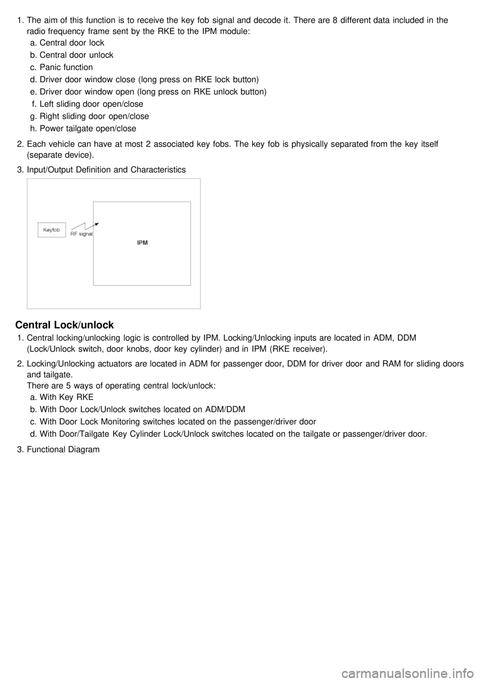
3. Input/Output Definition and Characteristics
Central Lock/unlock
1.Central locking/unlocking logic is controlled by IPM. Locking/Unlocking inputs are located in ADM, DDM
(Lock/Unlock switch, door knobs, door key cylinder) and in IPM (RKE receiver).
2. Locking/Unlocking actuators are located in ADM for passenger door, DDM for driver door and RAM for sliding doors
and tailgate.
There are 5 ways of operating central lock/unlock:
a. With Key RKE
b. With Door Lock/Unlock switches located on ADM/DDM
c. With Door Lock Monitoring switches located on the passenger/driver door
d. With Door/Tailgate Key Cylinder Lock/Unlock switches located on the tailgate or passenger/driver door.
3. Functional Diagram
Page 1504 of 1575

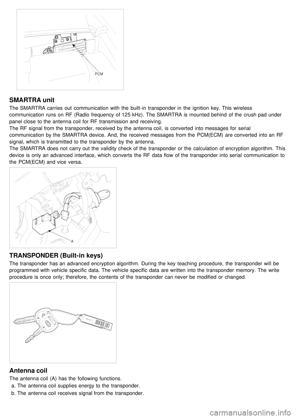
SMARTRA unit
The SMARTRA carries out communication with the built- in transponder in the ignition key. This wireless
communication runs on RF (Radio frequency of 125 kHz). The SMARTRA is mounted behind of the crush pad under
panel close to the antenna coil for RF transmission and receiving.
The RF signal from the transponder, received by the antenna coil, is converted into messages for serial
communication by the SMARTRA device. And, the received messages from the PCM(ECM) are converted into an RF
signal, which is transmitted to the transponder by the antenna.
The SMARTRA does not carry out the validity check of the transponder or the calculation of encryption algorithm. This
device is only an advanced interface, which converts the RF data flow of the transponder into serial communication to
the PCM(ECM) and vice versa.
TRANSPONDER (Built-in keys)
The transponder has an advanced encryption algorithm. During the key teaching procedure, the transponder will be
programmed with vehicle specific data. The vehicle specific data are written into the transponder memory. The write
procedure is once only; therefore, the contents of the transponder can never be modified or changed.
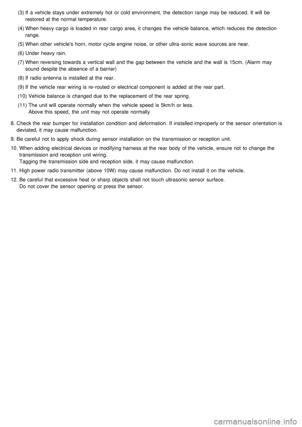
Antenna coil
The antenna coil (A) has the following functions.a. The antenna coil supplies energy to the transponder.
b. The antenna coil receives signal from the transponder.
Page 1538 of 1575

(3)If a vehicle stays under extremely hot or cold environment, the detection range may be reduced. It will be
restored at the normal temperature.
(4) When heavy cargo is loaded in rear cargo area, it changes the vehicle balance, which reduces the detection
range.
(5) When other vehicle's horn, motor cycle engine noise, or other ultra - sonic wave sources are near.
(6) Under heavy rain.
(7) When reversing towards a vertical wall and the gap between the vehicle and the wall is 15cm. (Alarm may
sound despite the absence of a barrier)
(8) If radio antenna is installed at the rear.
(9) If the vehicle rear wiring is re- routed or electrical component is added at the rear part.
(10) Vehicle balance is changed due to the replacement of the rear spring.
(11) The unit will operate normally when the vehicle speed is 5km/h or less.
Above this speed, the unit may not operate normally
8. Check the rear bumper for installation condition and deformation. If installed improperly or the sensor orientation is
deviated, it may cause malfunction.
9. Be careful not to apply shock during sensor installation on the transmission or reception unit.
10. When adding electrical devices or modifying harness at the rear body of the vehicle, ensure not to change the
transmission and reception unit wiring.
Tagging the transmission side and reception side, it may cause malfunction.
11. High power radio transmitter (above 10W) may cause malfunction. Do not install it on the vehicle.
12. Be careful that excessive heat or sharp objects shall not touch ultrasonic sensor surface.
Do not cover the sensor opening or press the sensor.