2007 KIA CARNIVAL Content
[x] Cancel search: ContentPage 665 of 1575

2007 > 2.7L V6 GASOLINE >
INSPECTION
Oil Specification
1. The HFC- 134a system requires synthetic (PAG) compressor oil whereas the R- 12 system requires mineral
compressor oil. The two oils must never be mixed.
2. Compressor (PAG) oil varies according to compressor model. Be sure to use oil specified for the model of
compressor.
Handling of Oil
1.The oil should be free from moisture, dust, metal powder, etc.
2. Do not mix with other oil.
3. The water content in the oil increases when exposed to the air. After use, seal oil from air immediately. (HFC - 134a
Compressor Oil absorbs moisture very easily.)
4. The compressor oil must be stored in steel containers, not in plastic containers.
Compressor oil check
The oil used to lubricate the compressor is circulating with the refrigerant.
Whenever replacing any component of the system or a large amount of gas leakage occurs, add oil to maintain the
original amount of oil.
Oil total volume in system:
120±10cc (4.05±0.34 fl.oz)
Oil Return Operation
There is close affinity between the oil and the refrigerant.
During normal operation, part of the oil recirculates with the refrigerant in the system. When checking the amount of
oil in the system, or replacing any component of the system, the compressor must be run in advance for oil return
operation. The procedure is as follows:
1. Open all the doors and the engine hood.
2. Start the engine and air conditioning switch to "ON" and set the blower motor control knob at its highest position.
3. Run the compressor for more than 20 minutes between 800 and 1,000 rpm in order to operate the system.
4. Stop the engine.
Replacement of Component Parts
When replacing the system component parts, supply the following amount of oil to the component parts to be installed.
Component parts to be installed Amount of Oil
Evaporator 50 cc (1.70 fl.oz)
Condenser 30 cc (1.02 fl.oz)
Receiver/dryer 30 cc (1.02 fl.oz)
Refrigerant line (One piece) 10 cc (0.34 fl.oz)
For compressor replacement, subtract the volume of oil drained from the removed compressor from the specified
volume, and drain the calculated volume of oil from the new compressor:
The specified volume - volume of removed compressor = volume to drain from the new compressor.
Even if no oil is drained from the removed compressor, don’t drain more than 50cc from new compressor.
Page 791 of 1575

2007 > 2.7L V6 GASOLINE >
Precautions
General Precautions
Please read the following precautions carefully before performing the airbag system service. Observe the instructions
described in this manual, or the airbags could accidentally deploy and cause damage or injuries. a. Except when performing electrical inspections, always turn the ignition switch OFF and disconnect the negative
cable from the battery, and wait at least three minutes before beginning work.
The contents in the memory are not erased even if the ignition switch is turned OFF or the battery cables are
disconnected from the battery.
b. Use the replacement parts which are manufactured to the same standards as the original parts and quality.
Do not install used SRS parts from another vehicle.
Use only new parts when making SRS repairs.
c. Carefully inspect any SRS part before you install it.
Do not install any part that shows signs of being dropped or improperly handled, such as dents, cracks or
deformation.
d.Before removing any of the SRS parts (including the disconnection of the connectors), always disconnect the SRS
connector.
Airbag Handling and Storage
Do not disassemble the airbags; it has no serviceable parts. Once an airbag has been deployed, it cannot be repaired
or reused.
For temporary storage of the air bag during service, please observe the following precautions.
a. Store the removed airbag with the pad surface up.
b. Keep free from any oil, grease, detergent, or water to prevent damage to the airbag assembly.
Page 1504 of 1575

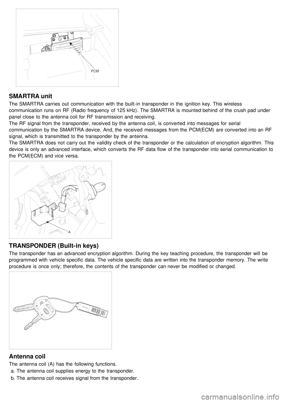
SMARTRA unit
The SMARTRA carries out communication with the built- in transponder in the ignition key. This wireless
communication runs on RF (Radio frequency of 125 kHz). The SMARTRA is mounted behind of the crush pad under
panel close to the antenna coil for RF transmission and receiving.
The RF signal from the transponder, received by the antenna coil, is converted into messages for serial
communication by the SMARTRA device. And, the received messages from the PCM(ECM) are converted into an RF
signal, which is transmitted to the transponder by the antenna.
The SMARTRA does not carry out the validity check of the transponder or the calculation of encryption algorithm. This
device is only an advanced interface, which converts the RF data flow of the transponder into serial communication to
the PCM(ECM) and vice versa.
TRANSPONDER (Built-in keys)
The transponder has an advanced encryption algorithm. During the key teaching procedure, the transponder will be
programmed with vehicle specific data. The vehicle specific data are written into the transponder memory. The write
procedure is once only; therefore, the contents of the transponder can never be modified or changed.
Antenna coil
The antenna coil (A) has the following functions.a. The antenna coil supplies energy to the transponder.
b. The antenna coil receives signal from the transponder.
Page 1508 of 1575

2007 > 2.7L V6 GASOLINE >
TEACHING PROCEDURES
1.Key Teaching Procedure
Key teaching must be done after replacing an inoperative PCM(ECM) or when providing additional keys to the
vehicle owner.
The procedure starts with an PCM(ECM) request for vehicle specific data (PIN code: 6digits) from the tester. The
"virgin" PCM(ECM) stores the vehicle specific data and the key teaching can be started. The "learnt" PCM(ECM)
compares the vehicle specific data from the tester with the stored data. If the data are correct, the teaching can
proceed.
If incorrect vehicle specific data have been sent to the PCM(ECM) three times, the PCM(ECM) will reject the
request of key teaching for one hour. This time cannot be reduced by disconnecting the battery or any other
manipulation. After reconnecting the battery, the timer starts again for one hour.
The key teaching is done by ignition on with the key and additional tester commands. The PCM(ECM) stores the
relevant data in the EEPROM and in the transponder. Then the PCM(ECM) runs the authentication required for
confirmation of the teaching process. The successful programming is then confirmed by a message to the tester.
If the key is already known to the PCM(ECM) from a previous teaching, the authentication will be accepted and the
EEPROM data are updated. There is no changed transponder content (this is impossible for a learnt transponder).
The attempt to repeatedly teach a key, which has been taught already during the same teaching cycle, is
recognized by the PCM(ECM). This rejects the key and a message is sent to the tester.
The PCM(ECM) rejects invalid keys, which are presented for teaching. A message is sent to the tester. The key
can be invalid due to faults in the transponder or other reasons, which result from unsuccessful programming of
data. If the PCM(ECM) detects different authenticators of a transponder and an PCM(ECM), the key is considered
to be invalid.
The maximum number of taught keys is 4
If an error occurs during the Immobilizer Service Menu, the PCM(ECM) status remains unchanged and a specific
fault code is stored.
If the PCM(ECM) status and the key status do not match for teaching of keys, the tester procedure will be stopped
and a specific fault code will be stored at PCM(ECM).