Page 1470 of 1575
2.The vehicle should be placed on a flat floor.
3. Check the suspension spring.
4. Draw vertical lines (Vertical lines passing through respective head lamp centers) and a horizontal line (Horizontal
line passing through center of head lamps) on the screen.
5. With the head lamp and battery in normal condition, aim the head lamps so the brightest portion falls on the
horizontal and vertical lines.
Make vertical and horizontal adjustments to the lower beam using the adjusting wheel.
FRONT FOG LAMP AIMING
The front fog lamps should be aimed as the same manner used to adjust the head lamps.
With the front fog lamps and battery normal condition, aim the front fog lamps by turning the adjusting gear (A).
HEAD LAMP AND FOG LAMP AIMING POINT
Page 1471 of 1575
1.Turn the low beam on with driver.
The cut- off line should be projected in the allowable range (shaded region).
Page 1496 of 1575

2007 > 2.7L V6 GASOLINE >
INSPECTION
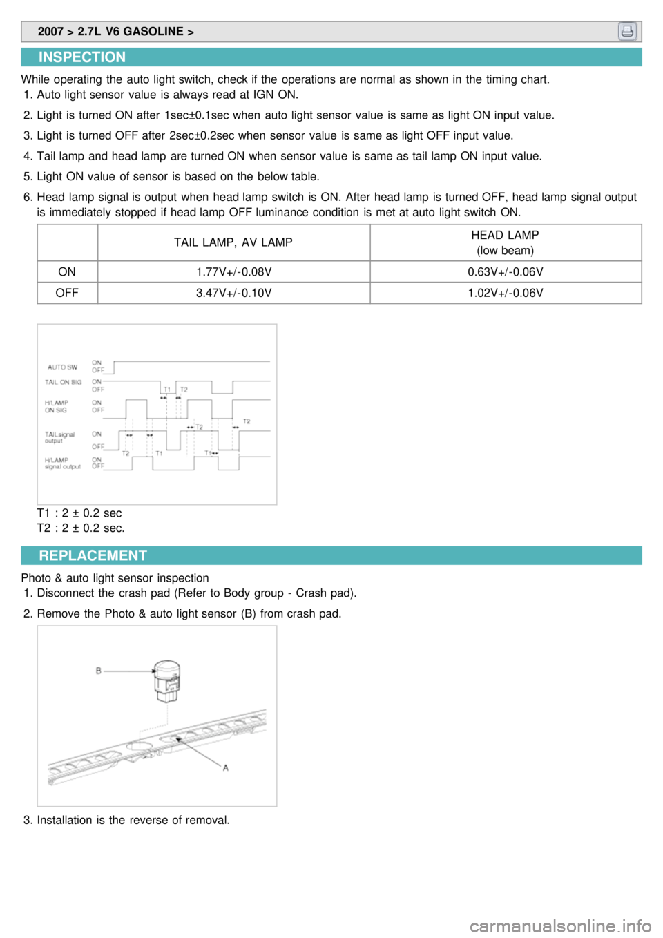
While operating the auto light switch, check if the operations are normal as shown in the timing chart.
1. Auto light sensor value is always read at IGN ON.
2. Light is turned ON after 1sec±0.1sec when auto light sensor value is same as light ON input value.
3. Light is turned OFF after 2sec±0.2sec when sensor value is same as light OFF input value.
4. Tail lamp and head lamp are turned ON when sensor value is same as tail lamp ON input value.
5. Light ON value of sensor is based on the below table.
6. Head lamp signal is output when head lamp switch is ON. After head lamp is turned OFF, head lamp signal output
is immediately stopped if head lamp OFF luminance condition is met at auto light switch ON.
TAIL LAMP, AV LAMP HEAD LAMP
(low beam)
ON 1.77V+/ - 0.08V 0.63V+/ - 0.06V
OFF 3.47V+/ - 0.10V 1.02V+/ - 0.06V
T1 : 2 ± 0.2 sec
T2 : 2 ± 0.2 sec.
REPLACEMENT
Photo & auto light sensor inspection
1. Disconnect the crash pad (Refer to Body group - Crash pad).
2. Remove the Photo & auto light sensor (B) from crash pad.
3.Installation is the reverse of removal.
Page:
< prev 1-8 9-16 17-24