Page 937 of 1575

c.Stop lamp switch circuit.
d. Check the hydraulic circuit for leakage.
Communication with Scan tool is not possible.
(Communication with any system is not possible) a.
Power source circuit
b. Diagnosis line
Communication with Scan tool is not possible.
(Communication with ABS only is not possible) a.
Power source circuit
b. Diagnosis line
c. HECU
When ignition key is turned ON (engine OFF), the ABS
warning lamp does not light up. a.
ABS warning lamp circuit
b. HECU
Even after the engine is started, the ABS warning lamp
remains ON. a.
ABS warning lamp circuit
b. HECU
During ABS operation, the brake pedal may vibrate or may not be able to be depressed. Such phenomena are
due to intermittent changes in hydraulic pressure inside the brake line to prevent the wheels from locking and is
not an abnormality.
DETECTING CONDITION
Trouble Symptoms Possible Cause
Brake operation varies depending on driving conditions and road
surface conditions, so diagnosis can be difficult.However if a normal
DTC is displayed, check the following probable cause. When the
problem is still occurring, replace the ABS control module. a.
Inoperative power source circuit
b. Inoperative wheel speed sensor circuit
c. Inoperative hydraulic circuit for leakage
d. Inoperative HECU
INSPECTION PROCEDURES
DTC INSPECTION
1. Connect the Scan Tool with the data link connector and turn the ignition switch ON.
2. Verify that the system is operating to specifications.
Is the system operating to specifications ?
▶ Check the power source circuit.
▶ Erase the DTC and recheck using Scan Tool.
CHECK THE POWER SOURCE CIRCUIT.
1. Disconnect the connector from the ABS control module.
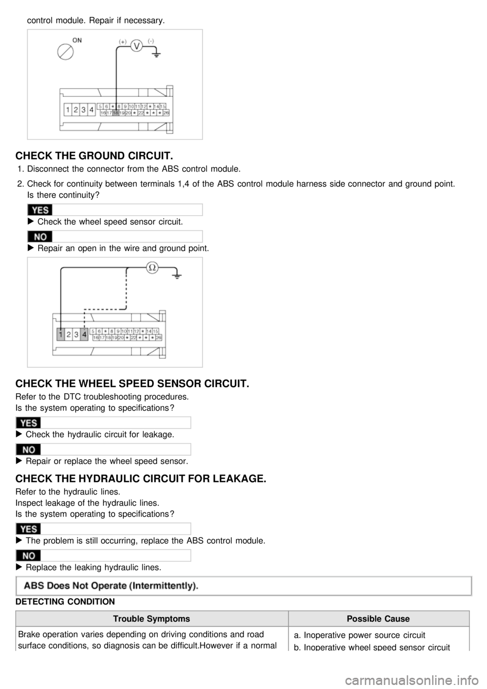
2. Turn the ignition switch ON, measure the voltage between terminal 18 of the ABS control module harness side
connector and body ground.
Specification: approximately B+
Is the voltage within specification?
▶ Check the ground circuit.
▶ Check the harness or connector between the fuse (10A) in the engine compartment junction block and the ABS
control module. Repair if necessary.
Page 938 of 1575

control module. Repair if necessary.
CHECK THE GROUND CIRCUIT.
1.Disconnect the connector from the ABS control module.
2. Check for continuity between terminals 1,4 of the ABS control module harness side connector and ground point.
Is there continuity?
▶ Check the wheel speed sensor circuit.
▶ Repair an open in the wire and ground point.
CHECK THE WHEEL SPEED SENSOR CIRCUIT.
Refer to the DTC troubleshooting procedures.
Is the system operating to specifications ?
▶ Check the hydraulic circuit for leakage.
▶ Repair or replace the wheel speed sensor.
CHECK THE HYDRAULIC CIRCUIT FOR LEAKAGE.
Refer to the hydraulic lines.
Inspect leakage of the hydraulic lines.
Is the system operating to specifications ?
▶ The problem is still occurring, replace the ABS control module.
▶ Replace the leaking hydraulic lines.
DETECTING CONDITION
Trouble Symptoms Possible Cause
Brake operation varies depending on driving conditions and road
surface conditions, so diagnosis can be difficult.However if a normal
DTC is displayed, check the following probable cause. When the a.
Inoperative power source circuit
b. Inoperative wheel speed sensor circuit
Page 939 of 1575

DTC is displayed, check the following probable cause. When the
problem is still occurring, replace the ABS control module.b.
Inoperative wheel speed sensor circuit
c. Inoperative hydraulic circuit for leakage
d. Inoperative HECU
INSPECTION PROCEDURES
DTC INSPECTION
1. Connect the Scan Tool with the data link connector and turn the ignition switch ON.
2. Verify that the system is operating to specifications.
Is the system operating to specifications ?
▶ Check the wheel speed sensor circuit.
▶ Erase the DTC and recheck using Scan Tool.
CHECK THE WHEEL SPEED SENSOR CIRCUIT.
Refer to the DTC troubleshooting procedures.
Is the system operating to specifications ?
▶ Check the stop lamp switch circuit.
▶ Repair or replace the wheel speed sensor.
CHECK THE STOP LAMP SWITCH CIRCUIT.
1. Check that stop lamp lights up when brake pedal is depressed and turns off when brake pedal is released.
2. Measure the voltage between terminal 20 of the ABS control module harness side connector and body ground
when brake pedal is depressed.
Specification: approximately B+
Is the voltage within specification?
▶ Check the hydraulic circuit for leakage.
▶ Repair the stop lamp switch. Repair an open in the wire between the ABS control module and the stop lamp
switch.
CHECK THE HYDRAULIC CIRCUIT FOR LEAKAGE.
Refer to the hydraulic lines.
Inspect leakage of the hydraulic lines.
Is the system operating to specifications ?
▶ The problem is still occurring, replace the ABS control module.
Page 969 of 1575
5.Select the variant coding.
6.Follow the next procedure according to the comment .
7.Confirm the condition , and then push the "REST".
8.If the procedure is finished, the screen is displayed as shown below.
9.IGN off.
10. IGN on.
11. The variant coding is completed.
Page 1334 of 1575

Bound cablesReplace drive unit if necessary
Binding or sticking of components Establish location of binding and replace
necessary components
Grade of vehicle too steep for power
operation Operate sliding door manually
Failure of sliding door motor assembly Replace motor assembly, if necessary
Squeaks, Noises and rattles Foreign material in Sliding Door Remove foreign material
Worn or Loose components Check and tighten loose components
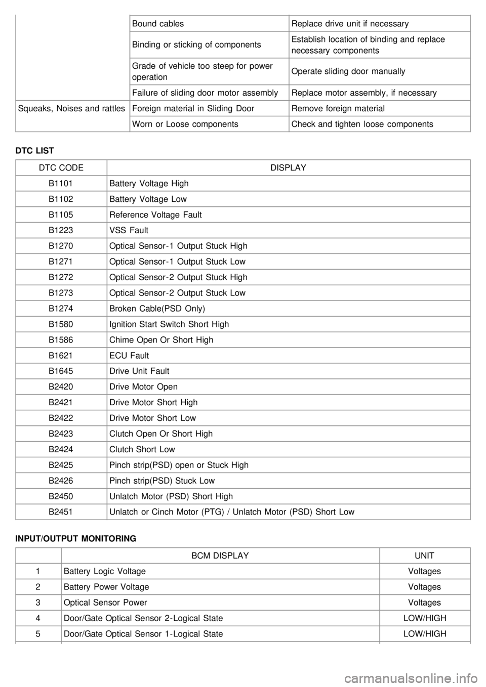
DTC LIST DTC CODE DISPLAY
B1101 Battery Voltage High
B1102 Battery Voltage Low
B1105 Reference Voltage Fault
B1223 VSS Fault
B1270 Optical Sensor - 1 Output Stuck High
B1271 Optical Sensor - 1 Output Stuck Low
B1272 Optical Sensor - 2 Output Stuck High
B1273 Optical Sensor - 2 Output Stuck Low
B1274 Broken Cable(PSD Only)
B1580 Ignition Start Switch Short High
B1586 Chime Open Or Short High
B1621 ECU Fault
B1645 Drive Unit Fault
B2420 Drive Motor Open
B2421 Drive Motor Short High
B2422 Drive Motor Short Low
B2423 Clutch Open Or Short High
B2424 Clutch Short Low
B2425 Pinch strip(PSD) open or Stuck High
B2426 Pinch strip(PSD) Stuck Low
B2450 Unlatch Motor (PSD) Short High
B2451 Unlatch or Cinch Motor (PTG) / Unlatch Motor (PSD) Short Low
INPUT/OUTPUT MONITORING BCM DISPLAY UNIT
1 Battery Logic Voltage Voltages
2 Battery Power Voltage Voltages
3 Optical Sensor Power Voltages
4 Door/Gate Optical Sensor 2 - Logical State LOW/HIGH
5 Door/Gate Optical Sensor 1 - Logical State LOW/HIGH
Page 1374 of 1575

Failure of tailgate motor assemblyMotor clutch does not engage, replace
assembly
Full open switch inoperative, replace switch, if
necessary
Troubleshoot using Body Diagnostic Manual
Replace motor, if necessary
Tailgate does not stay open Failure of tailgate gas struts Replace gas struts
Check for broken attachments
High inside/outside opening
effort Failure of tailgate gas struts
Replace gas struts
Check for broken attachments
Drive unit jammed or did not disengage Troubleshoot using Body Diagnostic Manual
Replace components, if necessary
Binding or sticking of components Establish location of binding and replace
necessary components
Tailgate continues to cinch
closed Failure of latch assembly
Check wire connections and for blown fuse
Check switches with SCAN tool
Tail gate continues to power
close Failure of latch assembly
Check wire connections
Check for foreign matter
Troubleshoot using Body Diagnostic Manual
Control Module Check for diagnostic trouble codes with Scan
tool
Wiring problems (system or vehicle) Troubleshoot using electrical schematics
Refer to wiring diagrams
Tailgate continues to power
open Failure of PTGM or BCM
Check for diagnostic trouble codes and cycle,
see Body Diagnostic Manual for detailed
procedures
Failure of motor assembly Check for continuous drive condition
Wiring problems (system or vehicle) Troubleshoot using electrical schematics
Refer to Wiring Diagrams
Tailgate opens very slowly Battery voltage at PTGM is too low
Check for proper voltage at the PTGM
Charge battery
Failure of tailgate gas struts Replace gas struts, if necessary
Binding or sticking of components Establish location of binding and replace
necessary components
Grade of vehicle too steep for power
operation Operate tailgate manually
Failure of tailgate motor assembly Replace motor assembly, if necessary
Squeaks, Noises and rattles Foreign material in tail gate
compartment
Remove foreign material
Worn/Loose components Check and tighten loose components
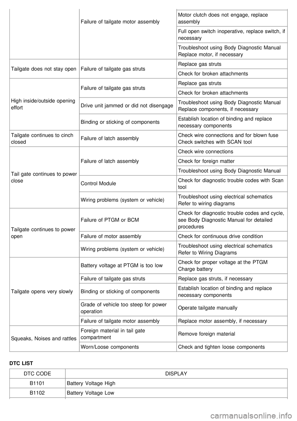
DTC LIST DTC CODE DISPLAY
B1101 Battery Voltage High
B1102 Battery Voltage Low
Page 1375 of 1575

B1105Reference Voltage Fault
B1223 VSS Fault
B1270 Optical Sensor - 1 Output Stuck High
B1271 Optical Sensor - 1 Output Stuck Low
B1272 Optical Sensor - 2 Output Stuck High
B1273 Optical Sensor - 2 Output Stuck Low
B1580 Ignition Start Switch Short High
B1585 Latch Switch Failure
B1621 ECU Defective
B1645 Drive Unit Failure
B2421 Drive Motor Short High
B2422 Drive Motor Short Low
B2423 Clutch Open Or Short High
B2424 Clutch Short Low
B2425 Left pinch strip open or Stuck High
B2426 Left pinch strip stuck Low
B2427 Right Pinch Strip Open Or Stuck High
B2428 Right Pinch Strip Stuck Low
B2450 Unlatch or Cinch Motor short High
B2451 Unlatch or Cinch Motor short Low
B2452 Cinch motor open (PTG Only)
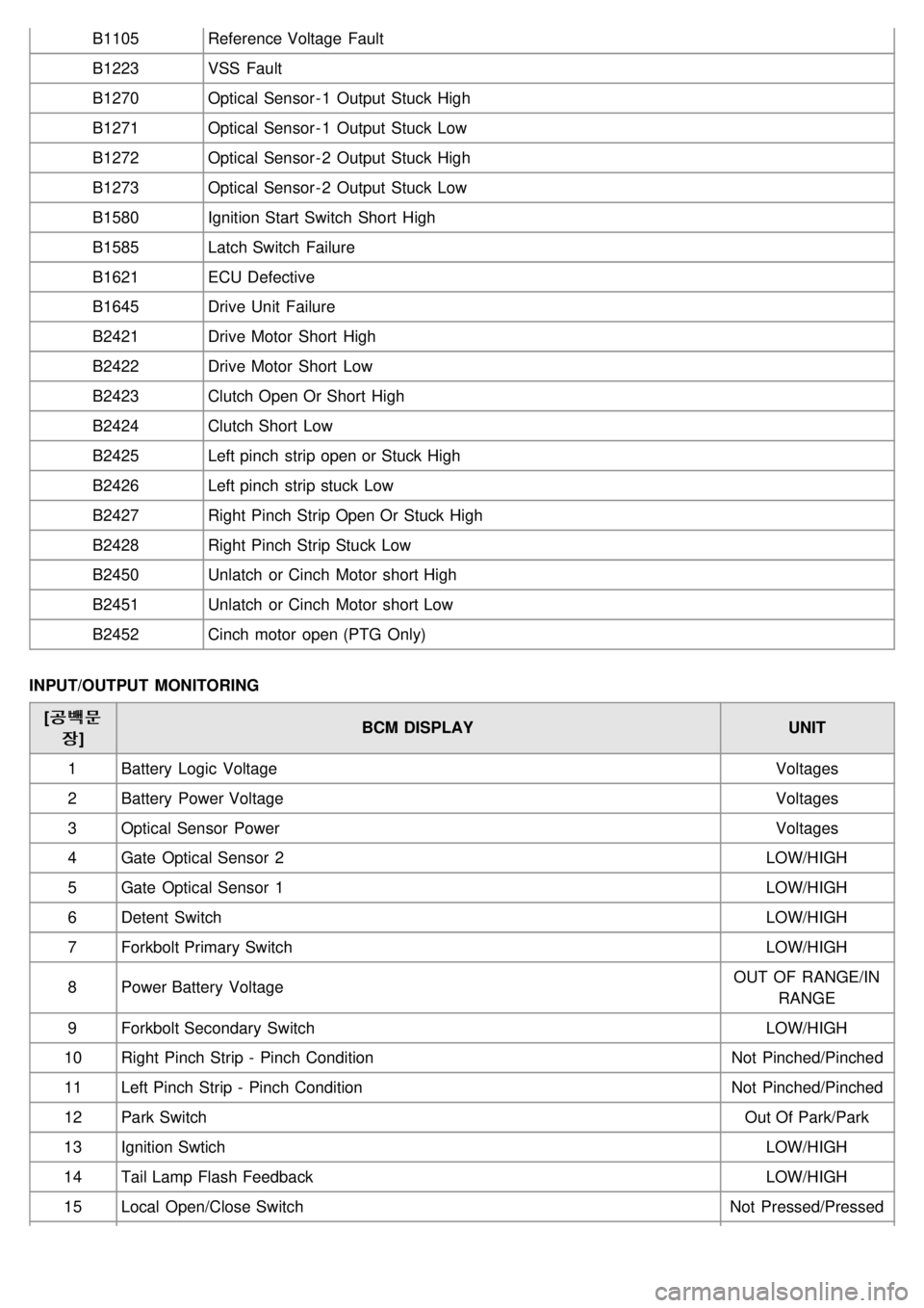
INPUT/OUTPUT MONITORING [�•�Ô�™�•�Ô�™
b
b] BCM DISPLAY
UNIT
1 Battery Logic Voltage Voltages
2 Battery Power Voltage Voltages
3 Optical Sensor Power Voltages
4 Gate Optical Sensor 2 LOW/HIGH
5 Gate Optical Sensor 1 LOW/HIGH
6 Detent Switch LOW/HIGH
7 Forkbolt Primary Switch LOW/HIGH
8 Power Battery Voltage OUT OF RANGE/IN
RANGE
9 Forkbolt Secondary Switch LOW/HIGH
10 Right Pinch Strip - Pinch Condition Not Pinched/Pinched
11 Left Pinch Strip - Pinch Condition Not Pinched/Pinched
12 Park Switch Out Of Park/Park
13 Ignition Swtich LOW/HIGH
14 Tail Lamp Flash Feedback LOW/HIGH
15 Local Open/Close Switch Not Pressed/Pressed
Page 1511 of 1575
(2)PCM(ECM) virgin status.
After replacing new "PCM(ECM)" scantool displays that PCM(ECM) is virgin status in Key Teaching mode.
"VIRGIN" status means that PCM(ECM) has not matched any PIN code before.