Page 618 of 1575
2007 > 2.7L V6 GASOLINE >
REPLACEMENT
1.Drain the power steering fluid.
2. Disconnect the pressure tube (A) and suction tube (B) from the power steering oil pump.
Tightening torque Nm (kgf.m, lb - ft):
55 ~ 65 (4.5 ~ 5.5, 40 ~ 47)
[Diesel]
[Gasoline]
3.Disconnect the pressure tube (A) and return tube from the valve body housing.
Tightening torque Nm (kgf.m, lb - ft):
12 ~ 18 (1.2 ~ 1.8, 9 ~ 13)
4.Remove the brackets of the pressure tube and hose from the sub- frame.
Page 619 of 1575
[Diesel]
[Gasoline]
5.Remove the bracket of the return tube and hose.
[Diesel]
[Gasoline]
Page 623 of 1575
2007 > 2.7L V6 GASOLINE >
REMOVAL
1.Disconnect the pressure tube (A) from the oil pump by loosening the eye bolt.
Tightening torque Nm (kgf- m, lb - ft):
65 ~ 75 (6.5 ~ 7.5, 47 ~ 54)
2. Disconnect the suction hose (B) from the suction pipe.
[Diesel]
[Gasoline]
3.Remove the drive belt.
4. Loosen the power steering pump mounting bolts, and then remove the power steering pump assembly (A) from the
pump bracket.
Tightening torque Nm (kgf.m lb - ft):
17 ~ 26 (1.7 ~ 2.6, 12 ~ 19)
[Diesel]
Page 624 of 1575
Tightening torque Nm (kgf.m lb - ft):
38 ~ 47 (3.8 ~ 4.7, 27 ~ 34)
[Diesel]
Tightening torque Nm (kgf.m lb - ft):
35 ~ 50 (3.5 ~ 5.0, 25 ~ 36)
[Gasoline]
Be careful not to spill fluid from the power steering oil pump.
INSTALLATION
1.Installation is the reverse of removal.
Page 728 of 1575

2007 > 2.7L V6 GASOLINE >
DESCRIPTION
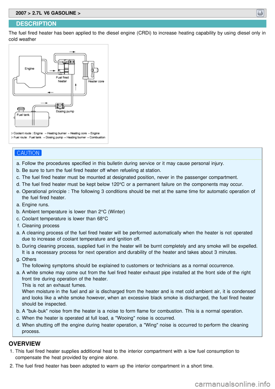
The fuel fired heater has been applied to the diesel engine (CRDi) to increase heating capability by using diesel only in
cold weather
a.Follow the procedures specified in this bulletin during service or it may cause personal injury.
b. Be sure to turn the fuel fired heater off when refueling at station.
c. The fuel fired heater must be mounted at designated position, never in the passenger compartment.
d. The fuel fired heater must be kept below 120°C or a permanent failure on the components may occur.
e. Operational principle : The following 3 conditions should be met at the same time for automatic operation of
the fuel fired heater.
a. Engine runs.
b. Ambient temperature is lower than 2°C (Winter)
c. Coolant temperature is lower than 68°C
f. Cleaning process
a. A cleaning process of the fuel fired heater will be performed automatically when the heater is not operated
due to increase of coolant temperature and ignition off.
b. During cleaning process, supplied fuel in the heater will be burnt completely and any smoke will be expelled.
It is a necessary process for next operation and durability of the heater and takes about 3 minutes.
g. Others
The following symptoms should be explained to customers or technicians as a normal occurrence.
a. A white smoke may come out from the fuel fired heater exhaust pipe installed at the front side of the right
front tire during operation of the heater.
This is not an exhaust fumes.
When moisture in the fuel and air is discharged from the heater and is met cold ambient air, it is condensed
and looks like a white smoke however, when an excessive black smoke is discharged, the fuel fired heater
should be inspected.
b. A "buk- buk" noise from the heater is a noise to form flame for combustion. This is a normal operation.
c. When the heater is operated at full load, a "Wooing" noise is occurred.
d. When shutting off the engine during heater operation, a "Wing" noise is occurred to perform the cleaning
process.
OVERVIEW
1.This fuel fired heater supplies additional heat to the interior compartment with a low fuel consumption to
compensate the heat provided by engine alone.
2. The fuel fired heater has been adopted to warm up the interior compartment in a short time.
Page 734 of 1575
2007 > 2.7L V6 GASOLINE >
SPECIFICATIONS
ITEM OPERATION STATESPECIFICATION
Fuel fired heater body Heater discharge
Full load
5.0kw
Half load 2.5kw
Full load Diesel
Fuel consumption Full load
0.63 l/h
Half load 0.32 l/h
Rated voltage �y12.0V
Operation voltage range �y9.5V~15.0V
Power consumption Full load
37w(Normal)
Half load 13w(Normal)
Permissible ambient temperature At operation
- 40°C~80°C
At storage - 40°C~120°C
Permissible operation pressure �y
0.4bar ~ 2.5bar
Minimum coolant flow volume �y
250 l/h
Permissible CO₂ value �y 8~13 vol %
ITEM SPECIFICATION
Dosing pump Rated voltage
12.0V
Operation voltage range 9.0V ~ 15.0V
Maximum power consumption 4w(Normal)
ITEM SPECIFICATION
Ambient switch Rated voltage
12.0V
Temperature of ON/OFF ON : 2°C(Tolerance : + 3°C, - 2°C)
OFF : 8°C(Tolerance : + 2°C, - 3°C)
Page 736 of 1575
2007 > 2.7L V6 GASOLINE >
DESCRIPTION
PTC (Positive Temperature Coefficient) heater (A) is an electric heater using a PTC element as an auxiliary heating
device that supplements deficiency of interior heat source in highly effective diesel engine (U engine).
An electric heater heats up the interior by directly heating the air that passes through the heater.
PTC = positive Temperature Coefficient
The name itself implies that the element has a proportional resistance change sensitive to temperature. PTC heater is
installed at the exit or the backside of heater core.
OPERATION PRINCIPLE
ECM outputs a PTC on signal. Operate PTC from 1st setting to 3rd setting with an interval of 15 seconds.
Heat up the air, which passes through a heater core.
OPERATION CONDITION
Judge the condition by ambient temperature is below 5°C, coolant temperature is below 70°C, and battery voltage is
above 11V and engine RPM is above 700RPM.
Page 1228 of 1575

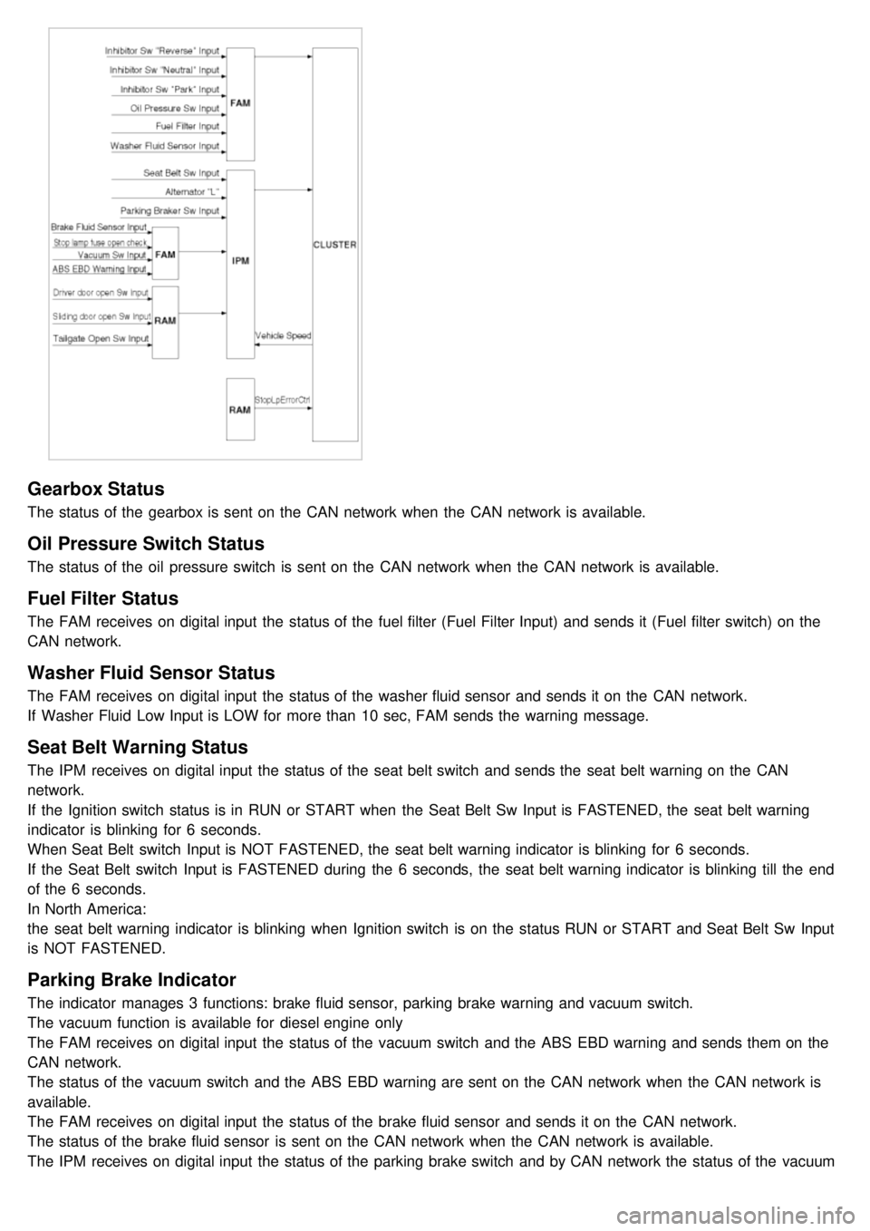
Gearbox Status
The status of the gearbox is sent on the CAN network when the CAN network is available.
Oil Pressure Switch Status
The status of the oil pressure switch is sent on the CAN network when the CAN network is available.
Fuel Filter Status
The FAM receives on digital input the status of the fuel filter (Fuel Filter Input) and sends it (Fuel filter switch) on the
CAN network.
Washer Fluid Sensor Status
The FAM receives on digital input the status of the washer fluid sensor and sends it on the CAN network.
If Washer Fluid Low Input is LOW for more than 10 sec, FAM sends the warning message.
Seat Belt Warning Status
The IPM receives on digital input the status of the seat belt switch and sends the seat belt warning on the CAN
network.
If the Ignition switch status is in RUN or START when the Seat Belt Sw Input is FASTENED, the seat belt warning
indicator is blinking for 6 seconds.
When Seat Belt switch Input is NOT FASTENED, the seat belt warning indicator is blinking for 6 seconds.
If the Seat Belt switch Input is FASTENED during the 6 seconds, the seat belt warning indicator is blinking till the end
of the 6 seconds.
In North America:
the seat belt warning indicator is blinking when Ignition switch is on the status RUN or START and Seat Belt Sw Input
is NOT FASTENED.
Parking Brake Indicator
The indicator manages 3 functions: brake fluid sensor, parking brake warning and vacuum switch.
The vacuum function is available for diesel engine only
The FAM receives on digital input the status of the vacuum switch and the ABS EBD warning and sends them on the
CAN network.
The status of the vacuum switch and the ABS EBD warning are sent on the CAN network when the CAN network is
available.
The FAM receives on digital input the status of the brake fluid sensor and sends it on the CAN network.
The status of the brake fluid sensor is sent on the CAN network when the CAN network is available.
The IPM receives on digital input the status of the parking brake switch and by CAN network the status of the vacuum
switch, the status of the ABS EBD warning, the status of the brake fluid sensor and the speed of the vehicle.