2007 ISUZU KB P190 sensor
[x] Cancel search: sensorPage 3311 of 6020
Engine Management – V6 – Diagnostics Page 6C1-2–33
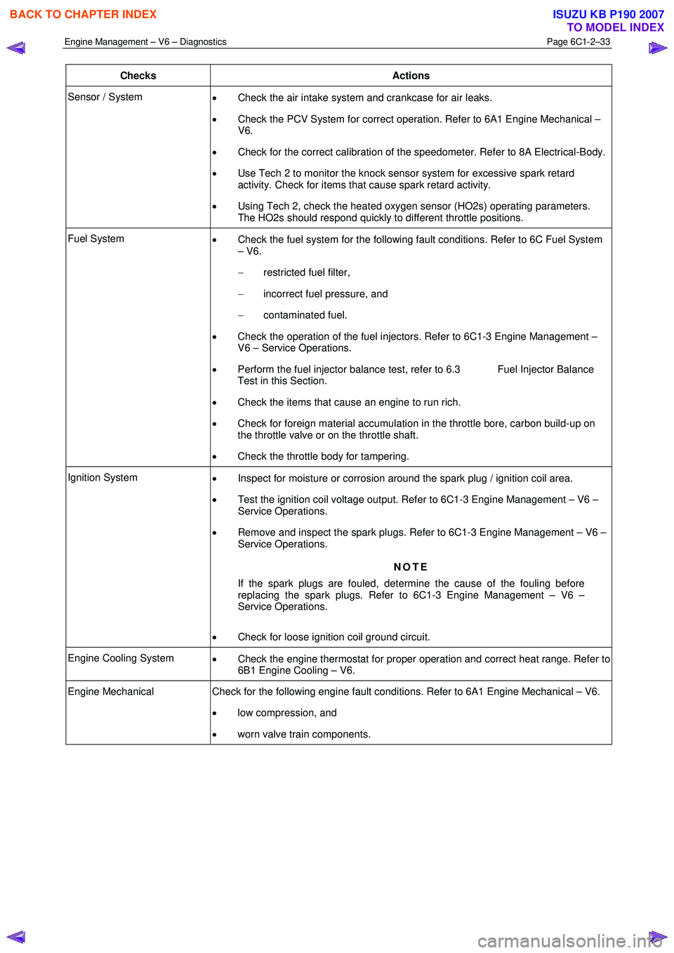
Checks Actions
Sensor / System
• Check the air intake system and crankcase for air leaks.
• Check the PCV System for correct operation. Refer to 6A1 Engine Mechanical –
V6.
• Check for the correct calibration of the speedometer. Refer to 8A Electrical-Body.
• Use Tech 2 to monitor the knock sensor system for excessive spark retard
activity. Check for items that cause spark retard activity.
• Using Tech 2, check the heated oxygen sensor (HO2s) operating parameters.
The HO2s should respond quickly to different throttle positions.
Fuel System • Check the fuel system for the following fault conditions. Refer to 6C Fuel System
– V6.
− restricted fuel filter,
− incorrect fuel pressure, and
− contaminated fuel.
• Check the operation of the fuel injectors. Refer to 6C1-3 Engine Management –
V6 – Service Operations.
• Perform the fuel injector balance test, refer to 6.3 Fuel Injector Balance
Test in this Section.
• Check the items that cause an engine to run rich.
• Check for foreign material accumulation in the throttle bore, carbon build-up on
the throttle valve or on the throttle shaft.
• Check the throttle body for tampering.
Ignition System
• Inspect for moisture or corrosion around the spark plug / ignition coil area.
• Test the ignition coil voltage output. Refer to 6C1-3 Engine Management – V6 –
Service Operations.
• Remove and inspect the spark plugs. Refer to 6C1-3 Engine Management – V6 –
Service Operations.
NOTE
If the spark plugs are fouled, determine the cause of the fouling before
replacing the spark plugs. Refer to 6C1-3 Engine Management – V6 –
Service Operations.
• Check for loose ignition coil ground circuit.
Engine Cooling System
• Check the engine thermostat for proper operation and correct heat range. Refer to
6B1 Engine Cooling – V6.
Engine Mechanical Check for the following engine fault conditions. Refer to 6A1 Engine Mechanical – V6.
• low compression, and
• worn valve train components.
BACK TO CHAPTER INDEX
TO MODEL INDEX
ISUZU KB P190 2007
Page 3312 of 6020
Engine Management – V6 – Diagnostics Page 6C1-2–34
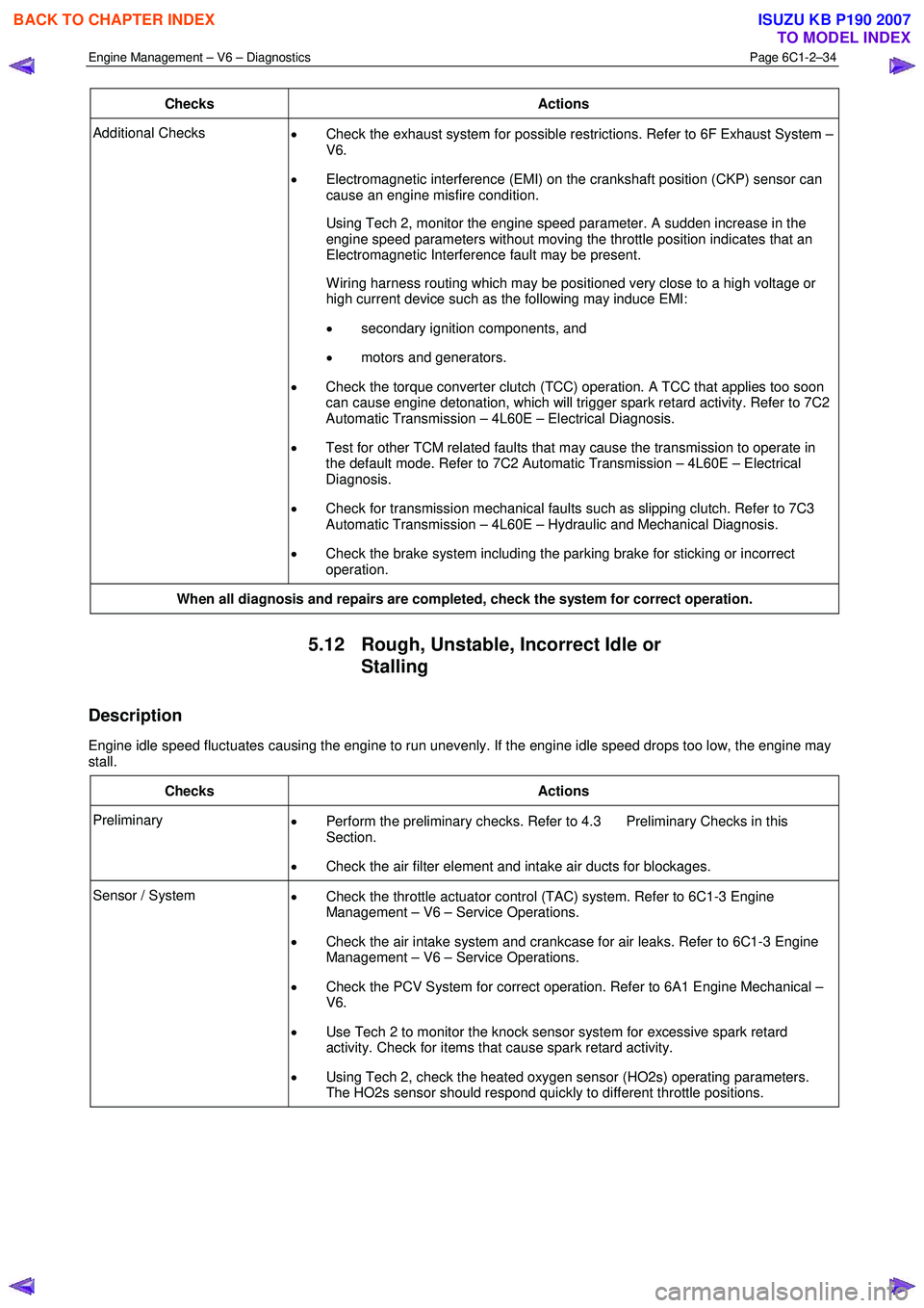
Checks Actions
Additional Checks
• Check the exhaust system for possible restrictions. Refer to 6F Exhaust System –
V6.
• Electromagnetic interference (EMI) on the crankshaft position (CKP) sensor can
cause an engine misfire condition.
Using Tech 2, monitor the engine speed parameter. A sudden increase in the engine speed parameters without moving the throttle position indicates that an
Electromagnetic Interference fault may be present.
W iring harness routing which may be positioned very close to a high voltage or high current device such as the following may induce EMI:
• secondary ignition components, and
• motors and generators.
• Check the torque converter clutch (TCC) operation. A TCC that applies too soon
can cause engine detonation, which will trigger spark retard activity. Refer to 7C2
Automatic Transmission – 4L60E – Electrical Diagnosis.
• Test for other TCM related faults that may cause the transmission to operate in
the default mode. Refer to 7C2 Automatic Transmission – 4L60E – Electrical
Diagnosis.
• Check for transmission mechanical faults such as slipping clutch. Refer to 7C3
Automatic Transmission – 4L60E – Hydraulic and Mechanical Diagnosis.
• Check the brake system including the parking brake for sticking or incorrect
operation.
When all diagnosis and repairs are completed, check the system for correct operation.
5.12 Rough, Unstable, Incorrect Idle or
Stalling
Description
Engine idle speed fluctuates causing the engine to run unevenly. If the engine idle speed drops too low, the engine may
stall.
Checks Actions
Preliminary • Perform the preliminary checks. Refer to 4.3 Preliminary Checks in this
Section.
• Check the air filter element and intake air ducts for blockages.
Sensor / System
• Check the throttle actuator control (TAC) system. Refer to 6C1-3 Engine
Management – V6 – Service Operations.
• Check the air intake system and crankcase for air leaks. Refer to 6C1-3 Engine
Management – V6 – Service Operations.
• Check the PCV System for correct operation. Refer to 6A1 Engine Mechanical –
V6.
• Use Tech 2 to monitor the knock sensor system for excessive spark retard
activity. Check for items that cause spark retard activity.
• Using Tech 2, check the heated oxygen sensor (HO2s) operating parameters.
The HO2s sensor should respond quickly to different throttle positions.
BACK TO CHAPTER INDEX
TO MODEL INDEX
ISUZU KB P190 2007
Page 3313 of 6020
Engine Management – V6 – Diagnostics Page 6C1-2–35
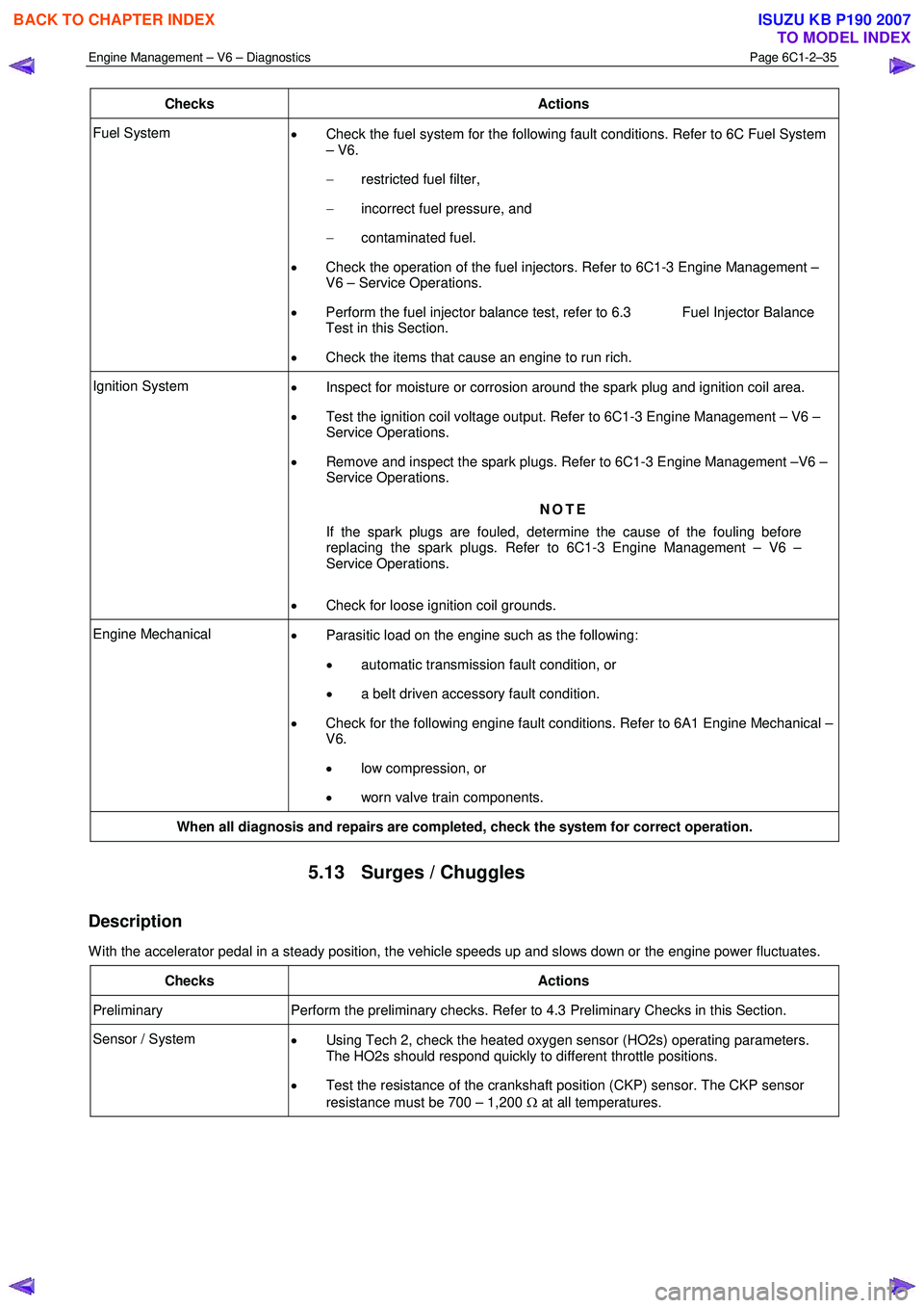
Checks Actions
Fuel System
• Check the fuel system for the following fault conditions. Refer to 6C Fuel System
– V6.
− restricted fuel filter,
− incorrect fuel pressure, and
− contaminated fuel.
• Check the operation of the fuel injectors. Refer to 6C1-3 Engine Management –
V6 – Service Operations.
• Perform the fuel injector balance test, refer to 6.3 Fuel Injector Balance
Test in this Section.
• Check the items that cause an engine to run rich.
Ignition System
• Inspect for moisture or corrosion around the spark plug and ignition coil area.
• Test the ignition coil voltage output. Refer to 6C1-3 Engine Management – V6 –
Service Operations.
• Remove and inspect the spark plugs. Refer to 6C1-3 Engine Management –V6 –
Service Operations.
NOTE
If the spark plugs are fouled, determine the cause of the fouling before
replacing the spark plugs. Refer to 6C1-3 Engine Management – V6 –
Service Operations.
• Check for loose ignition coil grounds.
Engine Mechanical
• Parasitic load on the engine such as the following:
• automatic transmission fault condition, or
• a belt driven accessory fault condition.
• Check for the following engine fault conditions. Refer to 6A1 Engine Mechanical –
V6.
• low compression, or
• worn valve train components.
When all diagnosis and repairs are completed, check the system for correct operation.
5.13 Surges / Chuggles
Description
W ith the accelerator pedal in a steady position, the vehicle speeds up and slows down or the engine power fluctuates.
Checks Actions
Preliminary Perform the preliminary checks. Refer to 4.3 Preliminary Checks in this Section.
Sensor / System
• Using Tech 2, check the heated oxygen sensor (HO2s) operating parameters.
The HO2s should respond quickly to different throttle positions.
• Test the resistance of the crankshaft position (CKP) sensor. The CKP sensor
resistance must be 700 – 1,200 Ω at all temperatures.
BACK TO CHAPTER INDEX
TO MODEL INDEX
ISUZU KB P190 2007
Page 3314 of 6020
Engine Management – V6 – Diagnostics Page 6C1-2–36
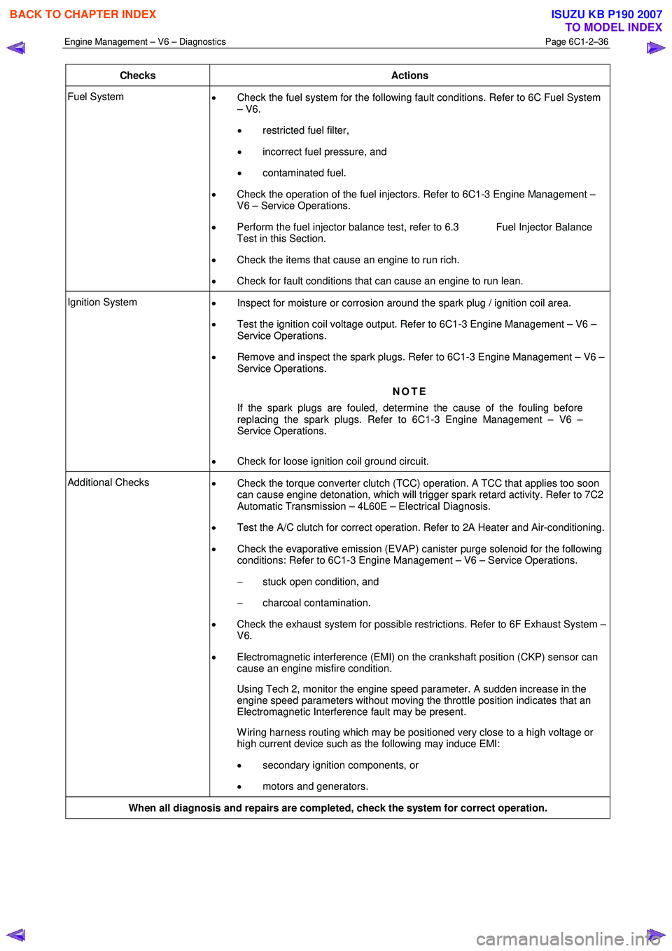
Checks Actions
Fuel System
• Check the fuel system for the following fault conditions. Refer to 6C Fuel System
– V6.
• restricted fuel filter,
• incorrect fuel pressure, and
• contaminated fuel.
• Check the operation of the fuel injectors. Refer to 6C1-3 Engine Management –
V6 – Service Operations.
• Perform the fuel injector balance test, refer to 6.3 Fuel Injector Balance
Test in this Section.
• Check the items that cause an engine to run rich.
• Check for fault conditions that can cause an engine to run lean.
Ignition System
• Inspect for moisture or corrosion around the spark plug / ignition coil area.
• Test the ignition coil voltage output. Refer to 6C1-3 Engine Management – V6 –
Service Operations.
• Remove and inspect the spark plugs. Refer to 6C1-3 Engine Management – V6 –
Service Operations.
NOTE
If the spark plugs are fouled, determine the cause of the fouling before
replacing the spark plugs. Refer to 6C1-3 Engine Management – V6 –
Service Operations.
• Check for loose ignition coil ground circuit.
Additional Checks
• Check the torque converter clutch (TCC) operation. A TCC that applies too soon
can cause engine detonation, which will trigger spark retard activity. Refer to 7C2
Automatic Transmission – 4L60E – Electrical Diagnosis.
• Test the A/C clutch for correct operation. Refer to 2A Heater and Air-conditioning.
• Check the evaporative emission (EVAP) canister purge solenoid for the following
conditions: Refer to 6C1-3 Engine Management – V6 – Service Operations.
− stuck open condition, and
− charcoal contamination.
• Check the exhaust system for possible restrictions. Refer to 6F Exhaust System –
V6.
• Electromagnetic interference (EMI) on the crankshaft position (CKP) sensor can
cause an engine misfire condition.
Using Tech 2, monitor the engine speed parameter. A sudden increase in the engine speed parameters without moving the throttle position indicates that an
Electromagnetic Interference fault may be present.
W iring harness routing which may be positioned very close to a high voltage or high current device such as the following may induce EMI:
• secondary ignition components, or
• motors and generators.
When all diagnosis and repairs are completed, check the system for correct operation.
BACK TO CHAPTER INDEX
TO MODEL INDEX
ISUZU KB P190 2007
Page 3325 of 6020
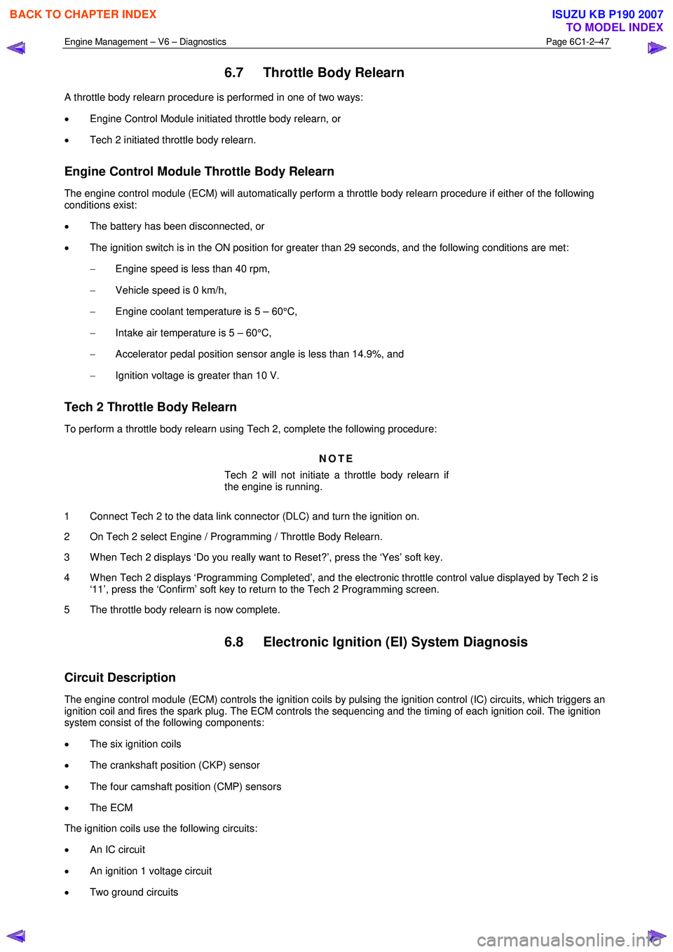
Engine Management – V6 – Diagnostics Page 6C1-2–47
6.7 Throttle Body Relearn
A throttle body relearn procedure is performed in one of two ways:
• Engine Control Module initiated throttle body relearn, or
• Tech 2 initiated throttle body relearn.
Engine Control Module Throttle Body Relearn
The engine control module (ECM) will automatically perform a throttle body relearn procedure if either of the following
conditions exist:
• The battery has been disconnected, or
• The ignition switch is in the ON position for greater than 29 seconds, and the following conditions are met:
− Engine speed is less than 40 rpm,
− Vehicle speed is 0 km/h,
− Engine coolant temperature is 5 – 60°C,
− Intake air temperature is 5 – 60°C,
− Accelerator pedal position sensor angle is less than 14.9%, and
− Ignition voltage is greater than 10 V.
Tech 2 Throttle Body Relearn
To perform a throttle body relearn using Tech 2, complete the following procedure:
NOTE
Tech 2 will not initiate a throttle body relearn if
the engine is running.
1 Connect Tech 2 to the data link connector (DLC) and turn the ignition on.
2 On Tech 2 select Engine / Programming / Throttle Body Relearn.
3 W hen Tech 2 displays ‘Do you really want to Reset?’, press the ‘Yes’ soft key.
4 W hen Tech 2 displays ‘Programming Completed’, and the electronic throttle control value displayed by Tech 2 is ‘11’, press the ‘Confirm’ soft key to return to the Tech 2 Programming screen.
5 The throttle body relearn is now complete.
6.8 Electronic Ignition (EI) System Diagnosis
Circuit Description
The engine control module (ECM) controls the ignition coils by pulsing the ignition control (IC) circuits, which triggers an
ignition coil and fires the spark plug. The ECM controls the sequencing and the timing of each ignition coil. The ignition
system consist of the following components:
• The six ignition coils
• The crankshaft position (CKP) sensor
• The four camshaft position (CMP) sensors
• The ECM
The ignition coils use the following circuits:
• An IC circuit
• An ignition 1 voltage circuit
• Two ground circuits
BACK TO CHAPTER INDEX
TO MODEL INDEX
ISUZU KB P190 2007
Page 3328 of 6020
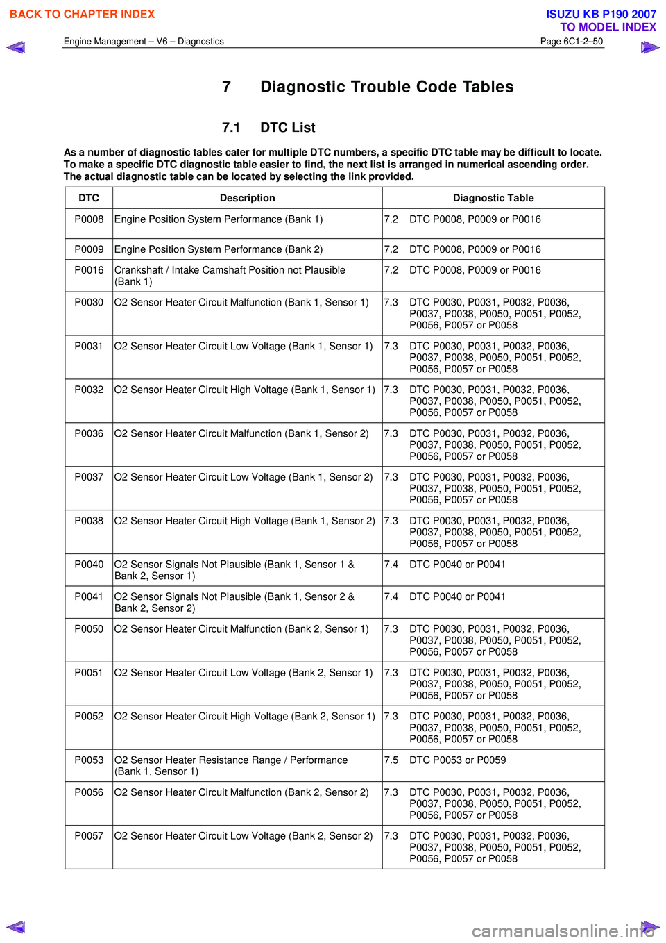
Engine Management – V6 – Diagnostics Page 6C1-2–50
7 Diagnostic Trouble Code Tables
7.1 DTC List
As a number of diagnostic tables cater for multiple DTC numbers, a specific DTC table may be difficult to locate.
To make a specific DTC diagnostic table easier to find, the next list is arranged in numerical ascending order.
The actual diagnostic table can be located by selecting the link provided.
DTC Description Diagnostic Table
P0008 Engine Position System Performance (Bank 1) 7.2 DTC P0008, P0009 or P0016
P0009 Engine Position System Performance (Bank 2) 7.2 DTC P0008, P0009 or P0016
P0016 Crankshaft / Intake Camshaft Position not Plausible
(Bank 1) 7.2 DTC P0008, P0009 or P0016
P0030 O2 Sensor Heater Circuit Malfunction (Bank 1, Sensor 1) 7.3 DTC P0030, P0031, P0032, P0036,
P0037, P0038, P0050, P0051, P0052,
P0056, P0057 or P0058
P0031 O2 Sensor Heater Circuit Low Voltage (Bank 1, Sensor 1) 7.3 DTC P0030, P0031, P0032, P0036, P0037, P0038, P0050, P0051, P0052,
P0056, P0057 or P0058
P0032 O2 Sensor Heater Circuit High Voltage (Bank 1, Sensor 1) 7.3 DTC P0030, P0031, P0032, P0036, P0037, P0038, P0050, P0051, P0052,
P0056, P0057 or P0058
P0036 O2 Sensor Heater Circuit Malfunction (Bank 1, Sensor 2) 7.3 DTC P0030, P0031, P0032, P0036, P0037, P0038, P0050, P0051, P0052,
P0056, P0057 or P0058
P0037 O2 Sensor Heater Circuit Low Voltage (Bank 1, Sensor 2) 7.3 DTC P0030, P0031, P0032, P0036, P0037, P0038, P0050, P0051, P0052,
P0056, P0057 or P0058
P0038 O2 Sensor Heater Circuit High Voltage (Bank 1, Sensor 2) 7.3 DTC P0030, P0031, P0032, P0036, P0037, P0038, P0050, P0051, P0052,
P0056, P0057 or P0058
P0040 O2 Sensor Signals Not Plausible (Bank 1, Sensor 1 & Bank 2, Sensor 1) 7.4 DTC P0040 or P0041
P0041 O2 Sensor Signals Not Plausible (Bank 1, Sensor 2 &
Bank 2, Sensor 2) 7.4 DTC P0040 or P0041
P0050 O2 Sensor Heater Circuit Malfunction (Bank 2, Sensor 1) 7.3 DTC P0030, P0031, P0032, P0036,
P0037, P0038, P0050, P0051, P0052,
P0056, P0057 or P0058
P0051 O2 Sensor Heater Circuit Low Voltage (Bank 2, Sensor 1) 7.3 DTC P0030, P0031, P0032, P0036, P0037, P0038, P0050, P0051, P0052,
P0056, P0057 or P0058
P0052 O2 Sensor Heater Circuit High Voltage (Bank 2, Sensor 1) 7.3 DTC P0030, P0031, P0032, P0036, P0037, P0038, P0050, P0051, P0052,
P0056, P0057 or P0058
P0053 O2 Sensor Heater Resistance Range / Performance (Bank 1, Sensor 1) 7.5 DTC P0053 or P0059
P0056 O2 Sensor Heater Circuit Malfunction (Bank 2, Sensor 2) 7.3 DTC P0030, P0031, P0032, P0036,
P0037, P0038, P0050, P0051, P0052,
P0056, P0057 or P0058
P0057 O2 Sensor Heater Circuit Low Voltage (Bank 2, Sensor 2) 7.3 DTC P0030, P0031, P0032, P0036, P0037, P0038, P0050, P0051, P0052,
P0056, P0057 or P0058
BACK TO CHAPTER INDEX
TO MODEL INDEX
ISUZU KB P190 2007
Page 3329 of 6020
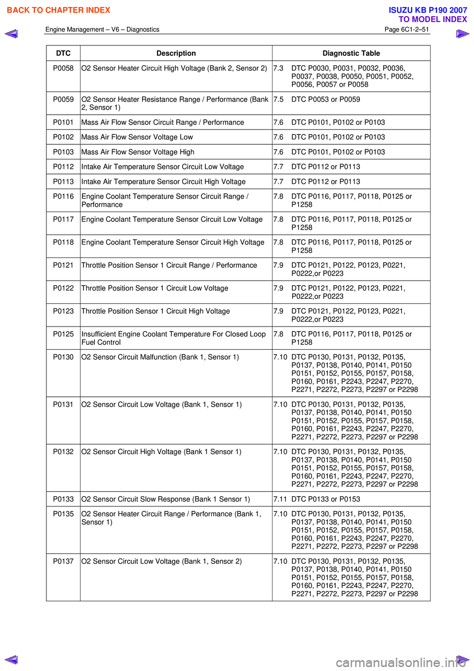
Engine Management – V6 – Diagnostics Page 6C1-2–51
DTC Description Diagnostic Table
P0058 O2 Sensor Heater Circuit High Voltage (Bank 2, Sensor 2) 7.3 DTC P0030, P0031, P0032, P0036,
P0037, P0038, P0050, P0051, P0052,
P0056, P0057 or P0058
P0059 O2 Sensor Heater Resistance Range / Performance (Bank 2, Sensor 1) 7.5 DTC P0053 or P0059
P0101 Mass Air Flow Sensor Circuit Range / Performance 7.6 DTC P0101, P0102 or P0103
P0102 Mass Air Flow Sensor Voltage Low
7.6 DTC P0101, P0102 or P0103
P0103 Mass Air Flow Sensor Voltage High 7.6 DTC P0101, P0102 or P0103
P0112 Intake Air Temperature Sensor Circuit Low Voltage 7.7 DTC P0112 or P0113
P0113 Intake Air Temperature Sensor Circuit High Voltage 7.7 DTC P0112 or P0113
P0116 Engine Coolant Temperature Sensor Circuit Range /
Performance 7.8 DTC P0116, P0117, P0118, P0125 or
P1258
P0117 Engine Coolant Temperature Sensor Circuit Low Voltage 7.8 DTC P0116, P0117, P0118, P0125 or P1258
P0118 Engine Coolant Temperature Sensor Circuit High Voltage 7.8 DTC P0116, P0117, P0118, P0125 or P1258
P0121 Throttle Position Sensor 1 Circuit Range / Performance 7.9 DTC P0121, P0122, P0123, P0221, P0222,or P0223
P0122 Throttle Position Sensor 1 Circuit Low Voltage 7.9 DTC P0121, P0122, P0123, P0221,
P0222,or P0223
P0123 Throttle Position Sensor 1 Circuit High Voltage 7.9 DTC P0121, P0122, P0123, P0221,
P0222,or P0223
P0125 Insufficient Engine Coolant Temperature For Closed Loop Fuel Control 7.8 DTC P0116, P0117, P0118, P0125 or
P1258
P0130 O2 Sensor Circuit Malfunction (Bank 1, Sensor 1) 7.10 DTC P0130, P0131, P0132, P0135, P0137, P0138, P0140, P0141, P0150
P0151, P0152, P0155, P0157, P0158,
P0160, P0161, P2243, P2247, P2270,
P2271, P2272, P2273, P2297 or P2298
P0131 O2 Sensor Circuit Low Voltage (Bank 1, Sensor 1) 7.10 DTC P0130, P0131, P0132, P0135, P0137, P0138, P0140, P0141, P0150
P0151, P0152, P0155, P0157, P0158,
P0160, P0161, P2243, P2247, P2270,
P2271, P2272, P2273, P2297 or P2298
P0132 O2 Sensor Circuit High Voltage (Bank 1 Sensor 1) 7.10 DTC P0130, P0131, P0132, P0135, P0137, P0138, P0140, P0141, P0150
P0151, P0152, P0155, P0157, P0158,
P0160, P0161, P2243, P2247, P2270,
P2271, P2272, P2273, P2297 or P2298
P0133 O2 Sensor Circuit Slow Response (Bank 1 Sensor 1) 7.11 DTC P0133 or P0153
P0135 O2 Sensor Heater Circuit Range / Performance (Bank 1, Sensor 1) 7.10 DTC P0130, P0131, P0132, P0135,
P0137, P0138, P0140, P0141, P0150
P0151, P0152, P0155, P0157, P0158,
P0160, P0161, P2243, P2247, P2270,
P2271, P2272, P2273, P2297 or P2298
P0137 O2 Sensor Circuit Low Voltage (Bank 1, Sensor 2) 7.10 DTC P0130, P0131, P0132, P0135, P0137, P0138, P0140, P0141, P0150
P0151, P0152, P0155, P0157, P0158,
P0160, P0161, P2243, P2247, P2270,
P2271, P2272, P2273, P2297 or P2298
BACK TO CHAPTER INDEX
TO MODEL INDEX
ISUZU KB P190 2007
Page 3330 of 6020
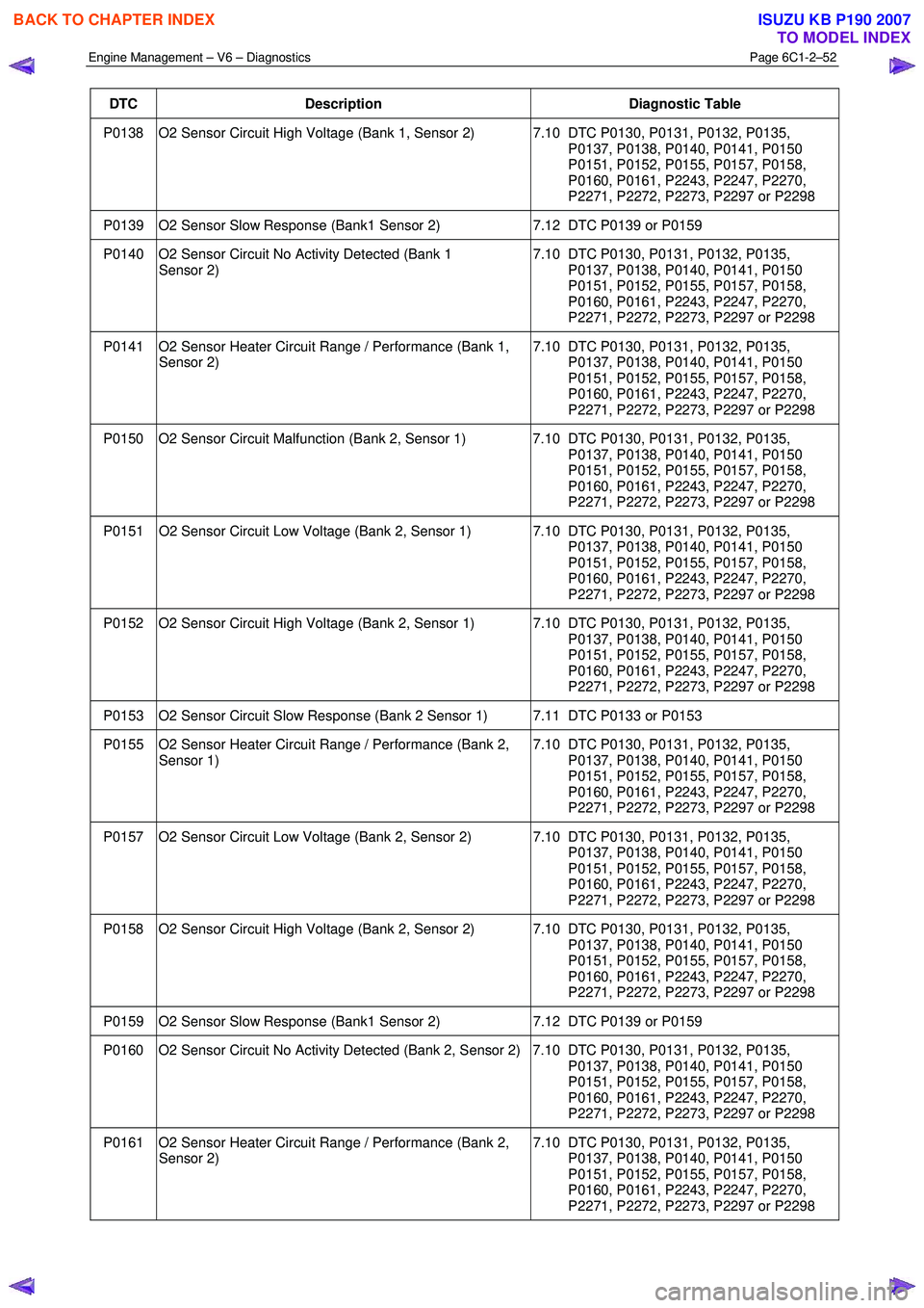
Engine Management – V6 – Diagnostics Page 6C1-2–52
DTC Description Diagnostic Table
P0138 O2 Sensor Circuit High Voltage (Bank 1, Sensor 2) 7.10 DTC P0130, P0131, P0132, P0135,
P0137, P0138, P0140, P0141, P0150
P0151, P0152, P0155, P0157, P0158,
P0160, P0161, P2243, P2247, P2270,
P2271, P2272, P2273, P2297 or P2298
P0139 O2 Sensor Slow Response (Bank1 Sensor 2) 7.12 DTC P0139 or P0159
P0140 O2 Sensor Circuit No Activity Detected (Bank 1
Sensor 2) 7.10 DTC P0130, P0131, P0132, P0135,
P0137, P0138, P0140, P0141, P0150
P0151, P0152, P0155, P0157, P0158,
P0160, P0161, P2243, P2247, P2270,
P2271, P2272, P2273, P2297 or P2298
P0141 O2 Sensor Heater Circuit Range / Performance (Bank 1, Sensor 2) 7.10 DTC P0130, P0131, P0132, P0135,
P0137, P0138, P0140, P0141, P0150
P0151, P0152, P0155, P0157, P0158,
P0160, P0161, P2243, P2247, P2270,
P2271, P2272, P2273, P2297 or P2298
P0150 O2 Sensor Circuit Malfunction (Bank 2, Sensor 1) 7.10 DTC P0130, P0131, P0132, P0135, P0137, P0138, P0140, P0141, P0150
P0151, P0152, P0155, P0157, P0158,
P0160, P0161, P2243, P2247, P2270,
P2271, P2272, P2273, P2297 or P2298
P0151 O2 Sensor Circuit Low Voltage (Bank 2, Sensor 1) 7.10 DTC P0130, P0131, P0132, P0135, P0137, P0138, P0140, P0141, P0150
P0151, P0152, P0155, P0157, P0158,
P0160, P0161, P2243, P2247, P2270,
P2271, P2272, P2273, P2297 or P2298
P0152 O2 Sensor Circuit High Voltage (Bank 2, Sensor 1) 7.10 DTC P0130, P0131, P0132, P0135, P0137, P0138, P0140, P0141, P0150
P0151, P0152, P0155, P0157, P0158,
P0160, P0161, P2243, P2247, P2270,
P2271, P2272, P2273, P2297 or P2298
P0153 O2 Sensor Circuit Slow Response (Bank 2 Sensor 1) 7.11 DTC P0133 or P0153
P0155 O2 Sensor Heater Circuit Range / Performance (Bank 2, Sensor 1) 7.10 DTC P0130, P0131, P0132, P0135,
P0137, P0138, P0140, P0141, P0150
P0151, P0152, P0155, P0157, P0158,
P0160, P0161, P2243, P2247, P2270,
P2271, P2272, P2273, P2297 or P2298
P0157 O2 Sensor Circuit Low Voltage (Bank 2, Sensor 2) 7.10 DTC P0130, P0131, P0132, P0135, P0137, P0138, P0140, P0141, P0150
P0151, P0152, P0155, P0157, P0158,
P0160, P0161, P2243, P2247, P2270,
P2271, P2272, P2273, P2297 or P2298
P0158 O2 Sensor Circuit High Voltage (Bank 2, Sensor 2) 7.10 DTC P0130, P0131, P0132, P0135, P0137, P0138, P0140, P0141, P0150
P0151, P0152, P0155, P0157, P0158,
P0160, P0161, P2243, P2247, P2270,
P2271, P2272, P2273, P2297 or P2298
P0159 O2 Sensor Slow Response (Bank1 Sensor 2) 7.12 DTC P0139 or P0159
P0160 O2 Sensor Circuit No Activity Detected (Bank 2, Sensor 2) 7.10 DTC P0130, P0131, P0132, P0135,
P0137, P0138, P0140, P0141, P0150
P0151, P0152, P0155, P0157, P0158,
P0160, P0161, P2243, P2247, P2270,
P2271, P2272, P2273, P2297 or P2298
P0161 O2 Sensor Heater Circuit Range / Performance (Bank 2, Sensor 2) 7.10 DTC P0130, P0131, P0132, P0135,
P0137, P0138, P0140, P0141, P0150
P0151, P0152, P0155, P0157, P0158,
P0160, P0161, P2243, P2247, P2270,
P2271, P2272, P2273, P2297 or P2298
BACK TO CHAPTER INDEX
TO MODEL INDEX
ISUZU KB P190 2007