2007 ISUZU KB P190 sensor
[x] Cancel search: sensorPage 3270 of 6020
Engine Management – V6 – General Information Page 6C1-1–28
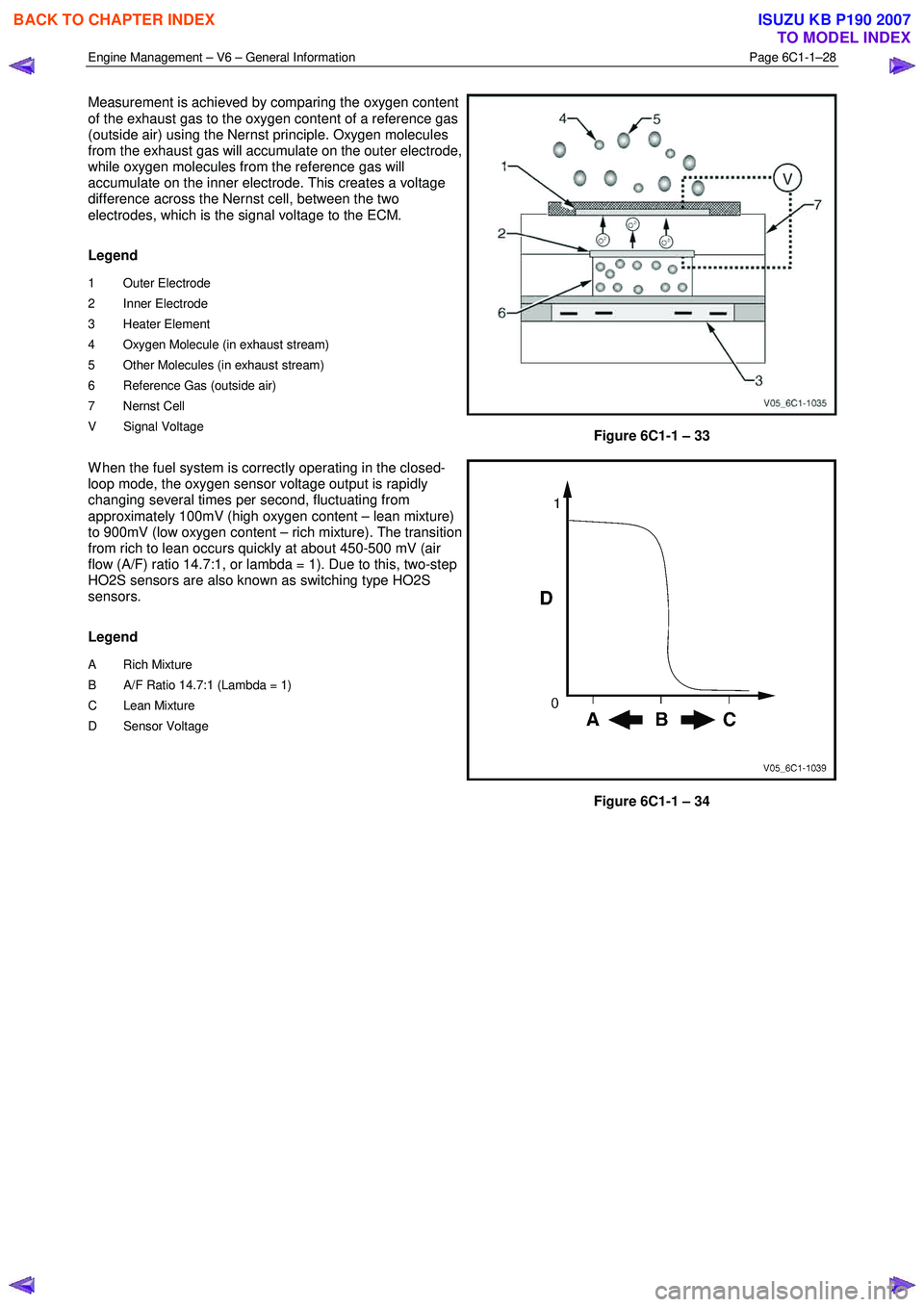
Measurement is achieved by comparing the oxygen content
of the exhaust gas to the oxygen content of a reference gas
(outside air) using the Nernst principle. Oxygen molecules
from the exhaust gas will accumulate on the outer electrode,
while oxygen molecules from the reference gas will
accumulate on the inner electrode. This creates a voltage
difference across the Nernst cell, between the two
electrodes, which is the signal voltage to the ECM.
Legend
1 Outer Electrode
2 Inner Electrode
3 Heater Element
4 Oxygen Molecule (in exhaust stream)
5 Other Molecules (in exhaust stream)
6 Reference Gas (outside air)
7 Nernst Cell
V Signal Voltage
Figure 6C1-1 – 33
W hen the fuel system is correctly operating in the closed-
loop mode, the oxygen sensor voltage output is rapidly
changing several times per second, fluctuating from
approximately 100mV (high oxygen content – lean mixture)
to 900mV (low oxygen content – rich mixture). The transition
from rich to lean occurs quickly at about 450-500 mV (air
flow (A/F) ratio 14.7:1, or lambda = 1). Due to this, two-step
HO2S sensors are also known as switching type HO2S
sensors.
Legend
A Rich Mixture
B A/F Ratio 14.7:1 (Lambda = 1)
C Lean Mixture
D Sensor Voltage
Figure 6C1-1 – 34
BACK TO CHAPTER INDEX
TO MODEL INDEX
ISUZU KB P190 2007
Page 3271 of 6020
Engine Management – V6 – General Information Page 6C1-1–29
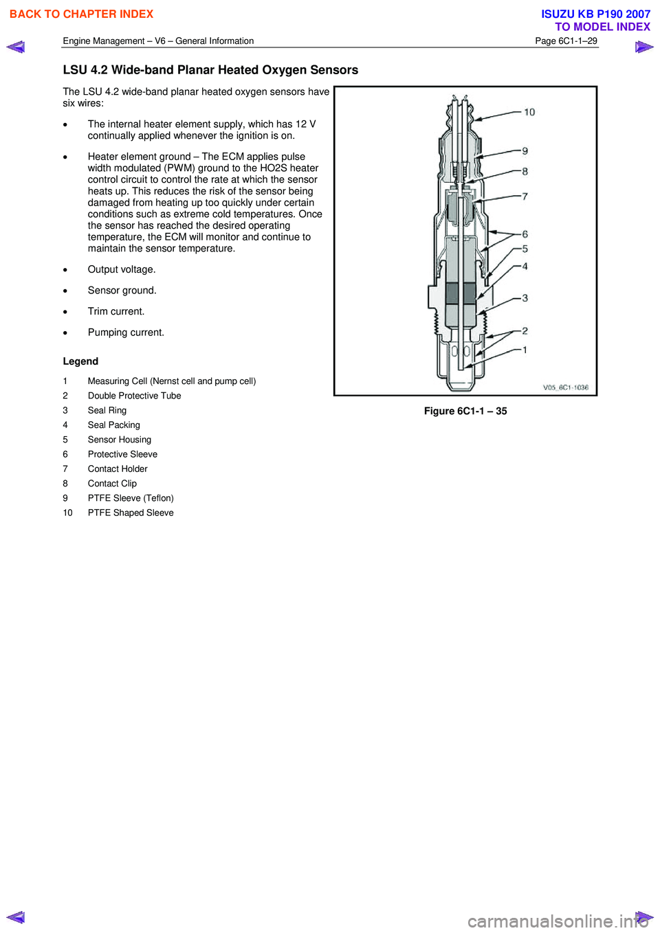
LSU 4.2 Wide-band Planar Heated Oxygen Sensors
The LSU 4.2 wide-band planar heated oxygen sensors have
six wires:
• The internal heater element supply, which has 12 V
continually applied whenever the ignition is on.
• Heater element ground – The ECM applies pulse
width modulated (PW M) ground to the HO2S heater
control circuit to control the rate at which the sensor
heats up. This reduces the risk of the sensor being
damaged from heating up too quickly under certain
conditions such as extreme cold temperatures. Once
the sensor has reached the desired operating
temperature, the ECM will monitor and continue to
maintain the sensor temperature.
• Output voltage.
• Sensor ground.
• Trim current.
• Pumping current.
Legend
1 Measuring Cell (Nernst cell and pump cell)
2 Double Protective Tube
3 Seal Ring
4 Seal Packing
5 Sensor Housing
6 Protective Sleeve
7 Contact Holder
8 Contact Clip
9 PTFE Sleeve (Teflon)
10 PTFE Shaped Sleeve
Figure 6C1-1 – 35
BACK TO CHAPTER INDEX
TO MODEL INDEX
ISUZU KB P190 2007
Page 3272 of 6020
Engine Management – V6 – General Information Page 6C1-1–30
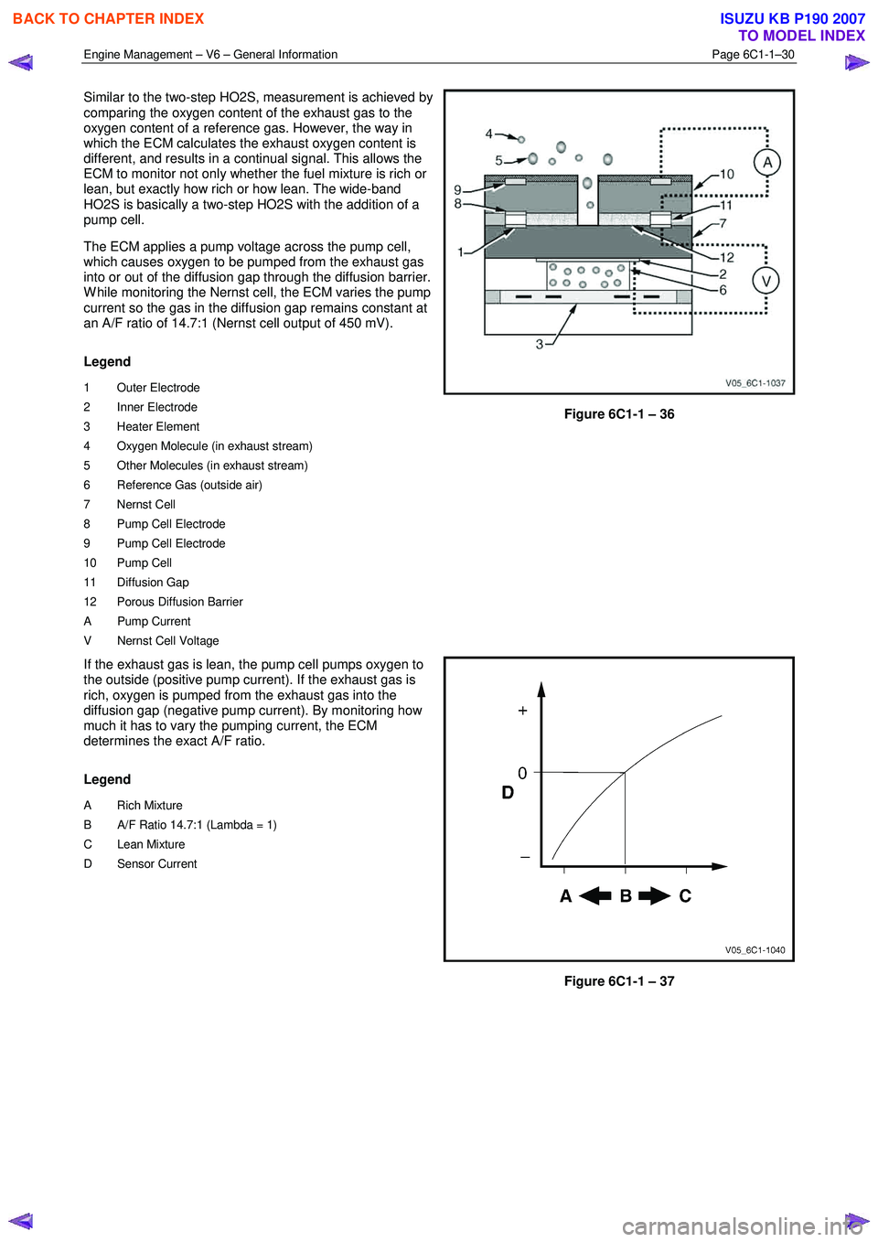
Similar to the two-step HO2S, measurement is achieved by
comparing the oxygen content of the exhaust gas to the
oxygen content of a reference gas. However, the way in
which the ECM calculates the exhaust oxygen content is
different, and results in a continual signal. This allows the
ECM to monitor not only whether the fuel mixture is rich or
lean, but exactly how rich or how lean. The wide-band
HO2S is basically a two-step HO2S with the addition of a
pump cell.
The ECM applies a pump voltage across the pump cell,
which causes oxygen to be pumped from the exhaust gas
into or out of the diffusion gap through the diffusion barrier.
W hile monitoring the Nernst cell, the ECM varies the pump
current so the gas in the diffusion gap remains constant at
an A/F ratio of 14.7:1 (Nernst cell output of 450 mV).
Legend
1 Outer Electrode
2 Inner Electrode
3 Heater Element
4 Oxygen Molecule (in exhaust stream)
5 Other Molecules (in exhaust stream)
6 Reference Gas (outside air)
7 Nernst Cell
8 Pump Cell Electrode
9 Pump Cell Electrode
10 Pump Cell
11 Diffusion Gap
12 Porous Diffusion Barrier
A Pump Current
V Nernst Cell Voltage
Figure 6C1-1 – 36
If the exhaust gas is lean, the pump cell pumps oxygen to
the outside (positive pump current). If the exhaust gas is
rich, oxygen is pumped from the exhaust gas into the
diffusion gap (negative pump current). By monitoring how
much it has to vary the pumping current, the ECM
determines the exact A/F ratio.
Legend
A Rich Mixture
B A/F Ratio 14.7:1 (Lambda = 1)
C Lean Mixture
D Sensor Current
Figure 6C1-1 – 37
BACK TO CHAPTER INDEX
TO MODEL INDEX
ISUZU KB P190 2007
Page 3273 of 6020
Engine Management – V6 – General Information Page 6C1-1–31
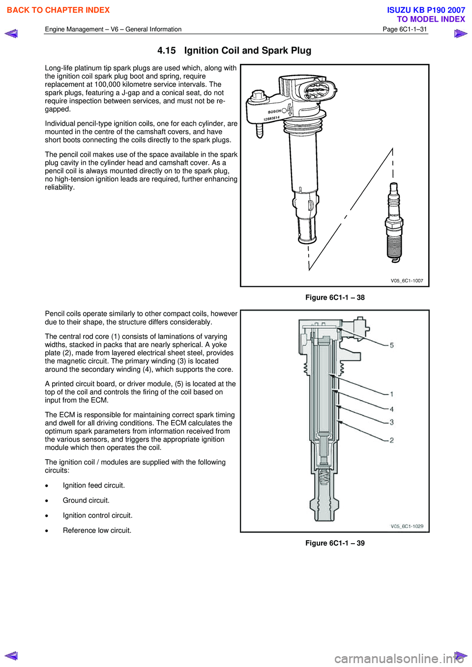
4.15 Ignition Coil and Spark Plug
Long-life platinum tip spark plugs are used which, along with
the ignition coil spark plug boot and spring, require
replacement at 100,000 kilometre service intervals. The
spark plugs, featuring a J-gap and a conical seat, do not
require inspection between services, and must not be re-
gapped.
Individual pencil-type ignition coils, one for each cylinder, are
mounted in the centre of the camshaft covers, and have
short boots connecting the coils directly to the spark plugs.
The pencil coil makes use of the space available in the spark
plug cavity in the cylinder head and camshaft cover. As a
pencil coil is always mounted directly on to the spark plug,
no high-tension ignition leads are required, further enhancing
reliability.
Figure 6C1-1 – 38
Pencil coils operate similarly to other compact coils, however
due to their shape, the structure differs considerably.
The central rod core (1) consists of laminations of varying
widths, stacked in packs that are nearly spherical. A yoke
plate (2), made from layered electrical sheet steel, provides
the magnetic circuit. The primary winding (3) is located
around the secondary winding (4), which supports the core.
A printed circuit board, or driver module, (5) is located at the
top of the coil and controls the firing of the coil based on
input from the ECM.
The ECM is responsible for maintaining correct spark timing
and dwell for all driving conditions. The ECM calculates the
optimum spark parameters from information received from
the various sensors, and triggers the appropriate ignition
module which then operates the coil.
The ignition coil / modules are supplied with the following
circuits:
• Ignition feed circuit.
• Ground circuit.
• Ignition control circuit.
• Reference low circuit.
Figure 6C1-1 – 39
BACK TO CHAPTER INDEX
TO MODEL INDEX
ISUZU KB P190 2007
Page 3274 of 6020
Engine Management – V6 – General Information Page 6C1-1–32
4.16 Intake Air Temperature Sensor
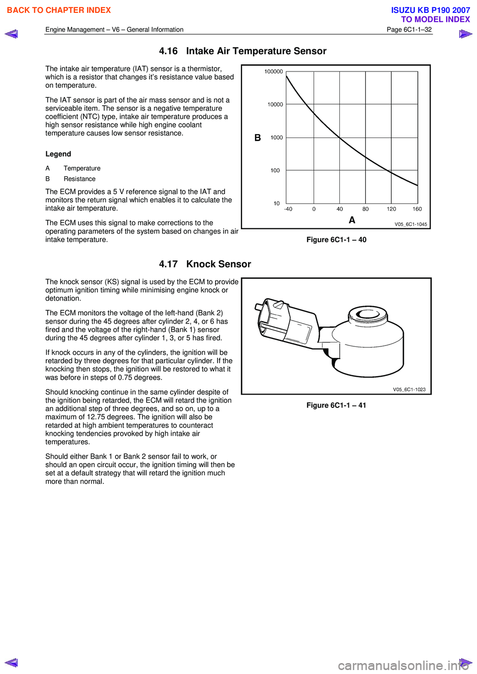
The intake air temperature (IAT) sensor is a thermistor,
which is a resistor that changes it’s resistance value based
on temperature.
The IAT sensor is part of the air mass sensor and is not a
serviceable item. The sensor is a negative temperature
coefficient (NTC) type, intake air temperature produces a
high sensor resistance while high engine coolant
temperature causes low sensor resistance.
Legend
A Temperature
B Resistance
The ECM provides a 5 V reference signal to the IAT and
monitors the return signal which enables it to calculate the
intake air temperature.
The ECM uses this signal to make corrections to the
operating parameters of the system based on changes in air
intake temperature.
Figure 6C1-1 – 40
4.17 Knock Sensor
The knock sensor (KS) signal is used by the ECM to provide
optimum ignition timing while minimising engine knock or
detonation.
The ECM monitors the voltage of the left-hand (Bank 2)
sensor during the 45 degrees after cylinder 2, 4, or 6 has
fired and the voltage of the right-hand (Bank 1) sensor
during the 45 degrees after cylinder 1, 3, or 5 has fired.
If knock occurs in any of the cylinders, the ignition will be
retarded by three degrees for that particular cylinder. If the
knocking then stops, the ignition will be restored to what it
was before in steps of 0.75 degrees.
Should knocking continue in the same cylinder despite of
the ignition being retarded, the ECM will retard the ignition
an additional step of three degrees, and so on, up to a
maximum of 12.75 degrees. The ignition will also be
retarded at high ambient temperatures to counteract
knocking tendencies provoked by high intake air
temperatures.
Should either Bank 1 or Bank 2 sensor fail to work, or
should an open circuit occur, the ignition timing will then be
set at a default strategy that will retard the ignition much
more than normal.
Figure 6C1-1 – 41
BACK TO CHAPTER INDEX
TO MODEL INDEX
ISUZU KB P190 2007
Page 3275 of 6020
Engine Management – V6 – General Information Page 6C1-1–33
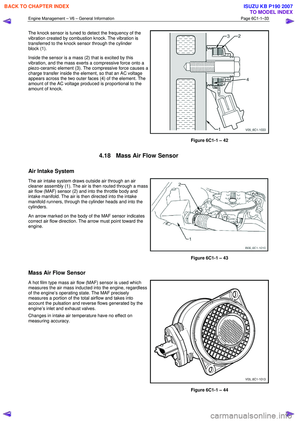
The knock sensor is tuned to detect the frequency of the
vibration created by combustion knock. The vibration is
transferred to the knock sensor through the cylinder
block (1).
Inside the sensor is a mass (2) that is excited by this
vibration, and the mass exerts a compressive force onto a
piezo-ceramic element (3). The compressive force causes a
charge transfer inside the element, so that an AC voltage
appears across the two outer faces (4) of the element. The
amount of the AC voltage produced is proportional to the
amount of knock.
Figure 6C1-1 – 42
4.18 Mass Air Flow Sensor
Air Intake System
The air intake system draws outside air through an air
cleaner assembly (1). The air is then routed through a mass
air flow (MAF) sensor (2) and into the throttle body and
intake manifold. The air is then directed into the intake
manifold runners, through the cylinder heads and into the
cylinders.
An arrow marked on the body of the MAF sensor indicates
correct air flow direction. The arrow must point toward the
engine.
Figure 6C1-1 – 43
Mass Air Flow Sensor
A hot film type mass air flow (MAF) sensor is used which
measures the air mass inducted into the engine, regardless
of the engine’s operating state. The MAF precisely
measures a portion of the total airflow and takes into
account the pulsation and reverse flows generated by the
engine’s inlet and exhaust valves.
Changes in intake air temperature have no effect on
measuring accuracy.
Figure 6C1-1 – 44
BACK TO CHAPTER INDEX
TO MODEL INDEX
ISUZU KB P190 2007
Page 3276 of 6020
Engine Management – V6 – General Information Page 6C1-1–34
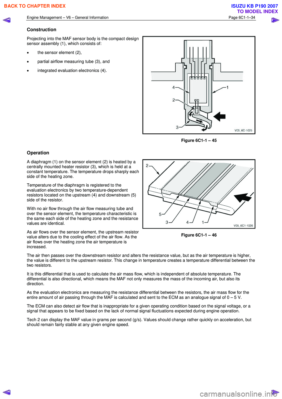
Construction
Projecting into the MAF sensor body is the compact design
sensor assembly (1), which consists of:
• the sensor element (2),
• partial airflow measuring tube (3), and
• integrated evaluation electronics (4).
Figure 6C1-1 – 45
Operation
A diaphragm (1) on the sensor element (2) is heated by a
centrally mounted heater resistor (3), which is held at a
constant temperature. The temperature drops sharply each
side of the heating zone.
Temperature of the diaphragm is registered to the
evaluation electronics by two temperature-dependent
resistors located on the upstream (4) and downstream (5)
side of the resistor.
W ith no air flow through the air flow measuring tube and
over the sensor element, the temperature characteristic is
the same each side of the heating zone and the resistance
values are identical.
As air flows over the sensor element, the upstream resistor
value alters due to the cooling effect of the air flow. As the
air flows over the heating zone the air temperature is
increased.
Figure 6C1-1 – 46
The air then passes over the downstream resistor and alters the resistance value, but as the air temperature is higher,
the value is different to the upstream resistor. This change in temperature creates a temperature differential between the
two resistors.
It is this differential that is used to calculate the air mass flow, which is independent of absolute temperature. The
differential is also directional, which means the MAF not only measures the mass of the incoming air, but also its
direction.
As the evaluation electronics are measuring the resistance differential between the resistors, the air mass flow for the
entire amount of air passing through the MAF is calculated and sent to the ECM as an analogue signal of 0 – 5 V.
The ECM can also detect air flow that is inappropriate for a given operating condition based on the signal voltage, or a
signal that appears to be fixed based on the lack of normal signal fluctuations expected during engine operation.
Tech 2 can display the MAF value in grams per second (g/s). Values should change rather quickly on acceleration, but
should remain fairly stable at any given engine speed.
BACK TO CHAPTER INDEX
TO MODEL INDEX
ISUZU KB P190 2007
Page 3277 of 6020
Engine Management – V6 – General Information Page 6C1-1–35
5 Abbreviations and Glossary of
Te r m s
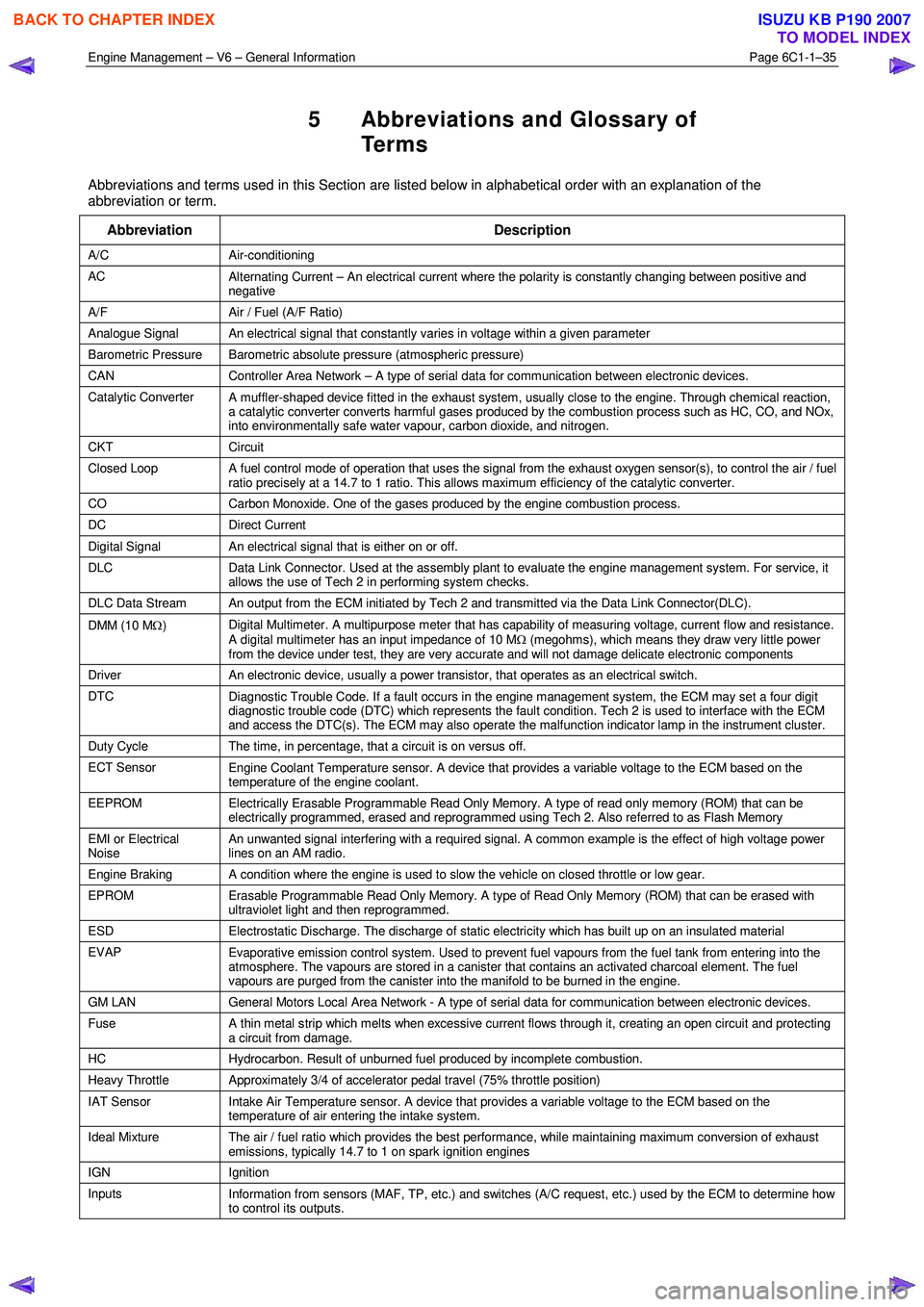
Abbreviations and terms used in this Section are listed below in alphabetical order with an explanation of the
abbreviation or term.
Abbreviation Description
A/C Air-conditioning
AC Alternating Current – An electrical current where the polarity is constantly changing between positive and
negative
A/F Air / Fuel (A/F Ratio)
Analogue Signal An electrical signal that constantly varies in voltage within a given parameter
Barometric Pressure Barometric absolute pressure (atmospheric pressure)
CAN Controller Area Network – A type of serial data for communication between electronic devices.
Catalytic Converter
A muffler-shaped device fitted in the exhaust system, usually close to the engine. Through chemical reaction,
a catalytic converter converts harmful gases produced by the combustion process such as HC, CO, and NOx,
into environmentally safe water vapour, carbon dioxide, and nitrogen.
CKT Circuit
Closed Loop A fuel control mode of operation that uses the signal from the exhaust oxygen sensor(s), to control the air / fuel
ratio precisely at a 14.7 to 1 ratio. This allows maximum efficiency of the catalytic converter.
CO Carbon Monoxide. One of the gases produced by the engine combustion process.
DC Direct Current
Digital Signal An electrical signal that is either on or off.
DLC
Data Link Connector. Used at the assembly plant to evaluate the engine management system. For service, it
allows the use of Tech 2 in performing system checks.
DLC Data Stream An output from the ECM initiated by Tech 2 and transmitted via the Data Link Connector(DLC).
DMM (10 M Ω) Digital Multimeter. A multipurpose meter that has capability of measuring voltage, current flow and resistance.
A digital multimeter has an input impedance of 10 M Ω (megohms), which means they draw very little power
from the device under test, they are very accurate and will not damage delicate electronic components
Driver An electronic device, usually a power transistor, that operates as an electrical switch.
DTC
Diagnostic Trouble Code. If a fault occurs in the engine management system, the ECM may set a four digit
diagnostic trouble code (DTC) which represents the fault condition. Tech 2 is used to interface with the ECM
and access the DTC(s). The ECM may also operate the malfunction indicator lamp in the instrument cluster.
Duty Cycle The time, in percentage, that a circuit is on versus off.
ECT Sensor
Engine Coolant Temperature sensor. A device that provides a variable voltage to the ECM based on the
temperature of the engine coolant.
EEPROM Electrically Erasable Programmable Read Only Memory. A type of read only memory (ROM) that can be
electrically programmed, erased and reprogrammed using Tech 2. Also referred to as Flash Memory
EMI or Electrical
Noise An unwanted signal interfering with a required signal. A common example is the effect of high voltage power
lines on an AM radio.
Engine Braking A condition where the engine is used to slow the vehicle on closed throttle or low gear.
EPROM Erasable Programmable Read Only Memory. A type of Read Only Memory (ROM) that can be erased with
ultraviolet light and then reprogrammed.
ESD Electrostatic Discharge. The discharge of static electricity which has built up on an insulated material
EVAP
Evaporative emission control system. Used to prevent fuel vapours from the fuel tank from entering into the
atmosphere. The vapours are stored in a canister that contains an activated charcoal element. The fuel
vapours are purged from the canister into the manifold to be burned in the engine.
GM LAN General Motors Local Area Network - A type of serial data for communication between electronic devices.
Fuse
A thin metal strip which melts when excessive current flows through it, creating an open circuit and protecting
a circuit from damage.
HC Hydrocarbon. Result of unburned fuel produced by incomplete combustion.
Heavy Throttle Approximately 3/4 of accelerator pedal travel (75% throttle position)
IAT Sensor
Intake Air Temperature sensor. A device that provides a variable voltage to the ECM based on the
temperature of air entering the intake system.
Ideal Mixture The air / fuel ratio which provides the best performance, while maintaining maximum conversion of exhaust
emissions, typically 14.7 to 1 on spark ignition engines
IGN Ignition
Inputs Information from sensors (MAF, TP, etc.) and switches (A/C request, etc.) used by the ECM to determine how
to control its outputs.
BACK TO CHAPTER INDEX
TO MODEL INDEX
ISUZU KB P190 2007