2007 ISUZU KB P190 sensor
[x] Cancel search: sensorPage 3262 of 6020
Engine Management – V6 – General Information Page 6C1-1–20
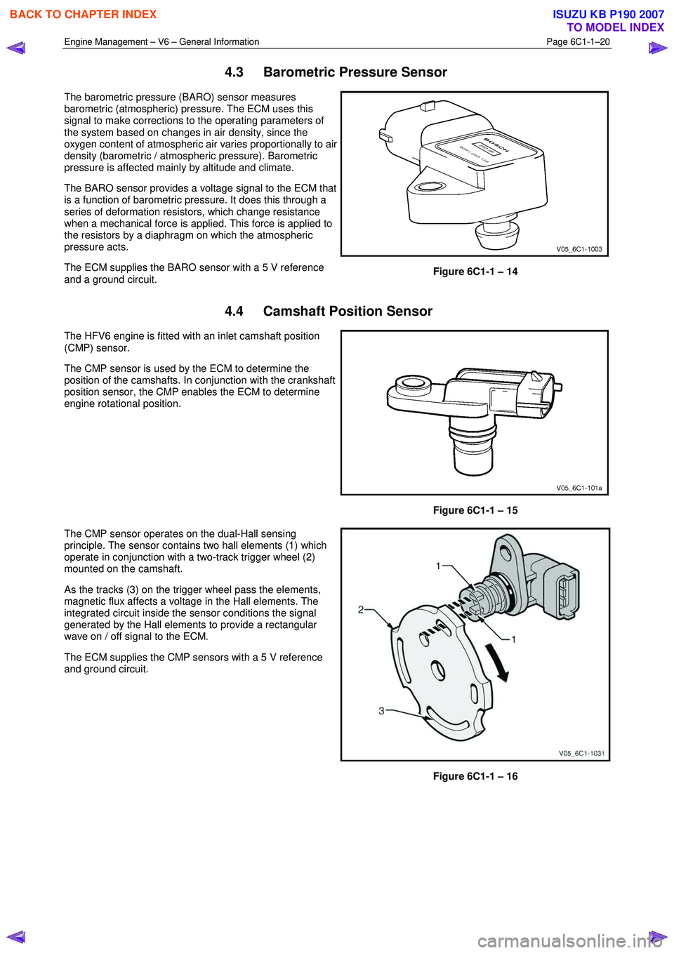
4.3 Barometric Pressure Sensor
The barometric pressure (BARO) sensor measures
barometric (atmospheric) pressure. The ECM uses this
signal to make corrections to the operating parameters of
the system based on changes in air density, since the
oxygen content of atmospheric air varies proportionally to air
density (barometric / atmospheric pressure). Barometric
pressure is affected mainly by altitude and climate.
The BARO sensor provides a voltage signal to the ECM that
is a function of barometric pressure. It does this through a
series of deformation resistors, which change resistance
when a mechanical force is applied. This force is applied to
the resistors by a diaphragm on which the atmospheric
pressure acts.
The ECM supplies the BARO sensor with a 5 V reference
and a ground circuit.
Figure 6C1-1 – 14
4.4 Camshaft Position Sensor
The HFV6 engine is fitted with an inlet camshaft position
(CMP) sensor.
The CMP sensor is used by the ECM to determine the
position of the camshafts. In conjunction with the crankshaft
position sensor, the CMP enables the ECM to determine
engine rotational position.
Figure 6C1-1 – 15
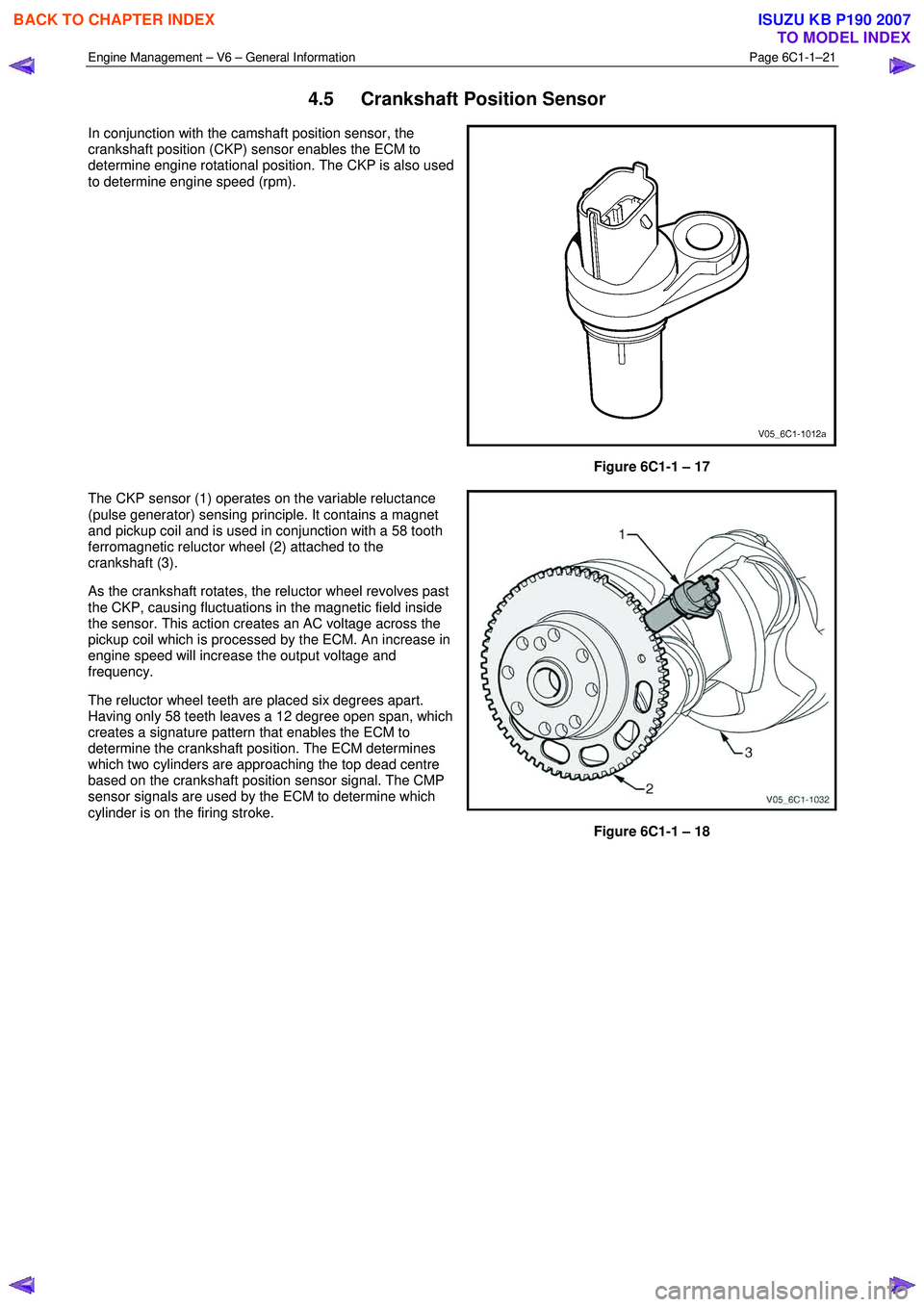
The CMP sensor operates on the dual-Hall sensing
principle. The sensor contains two hall elements (1) which
operate in conjunction with a two-track trigger wheel (2)
mounted on the camshaft.
As the tracks (3) on the trigger wheel pass the elements,
magnetic flux affects a voltage in the Hall elements. The
integrated circuit inside the sensor conditions the signal
generated by the Hall elements to provide a rectangular
wave on / off signal to the ECM.
The ECM supplies the CMP sensors with a 5 V reference
and ground circuit.
Figure 6C1-1 – 16
BACK TO CHAPTER INDEX
TO MODEL INDEX
ISUZU KB P190 2007
Page 3263 of 6020
Engine Management – V6 – General Information Page 6C1-1–21
4.5 Crankshaft Position Sensor
In conjunction with the camshaft position sensor, the
crankshaft position (CKP) sensor enables the ECM to
determine engine rotational position. The CKP is also used
to determine engine speed (rpm).
Figure 6C1-1 – 17
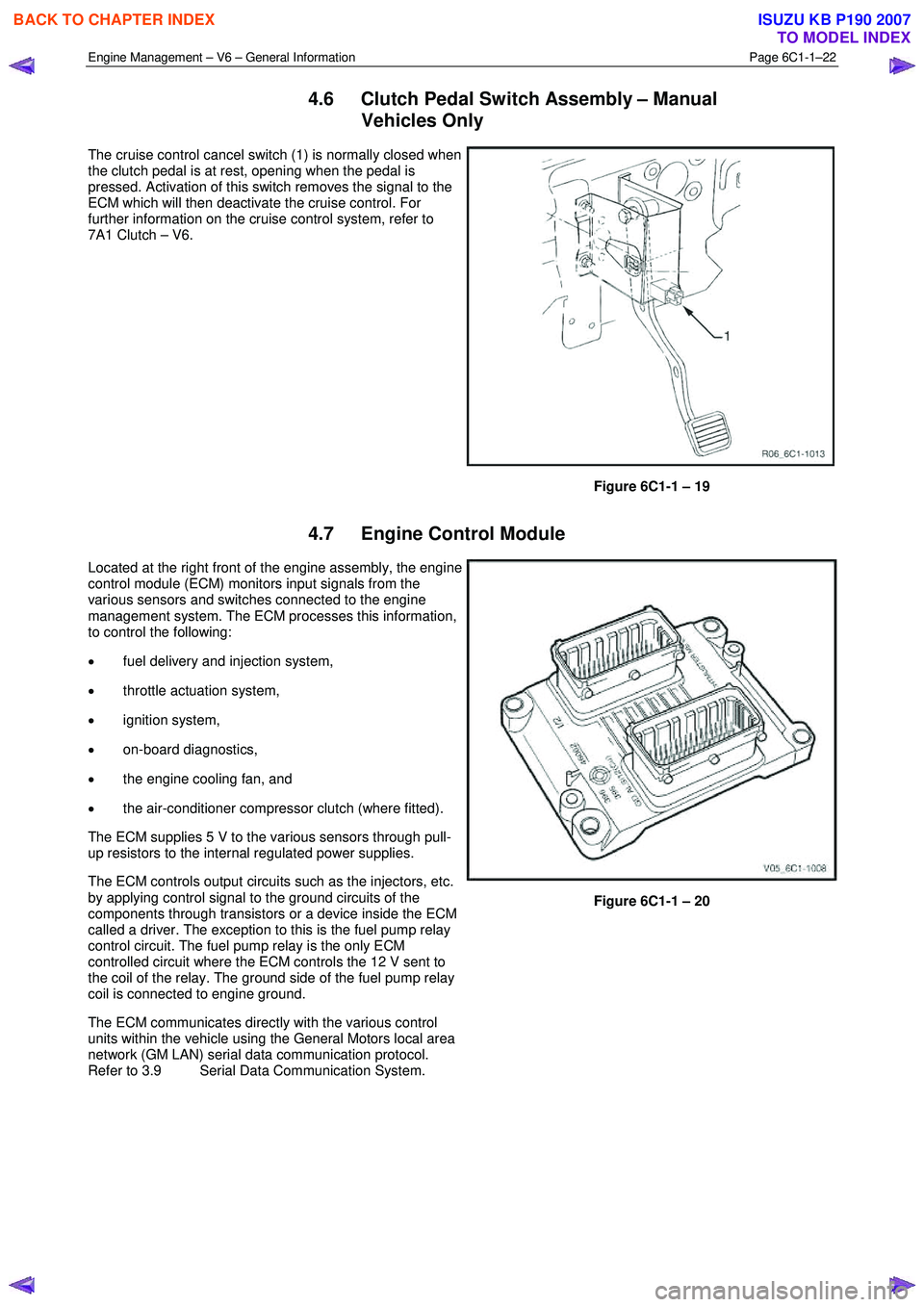
The CKP sensor (1) operates on the variable reluctance
(pulse generator) sensing principle. It contains a magnet
and pickup coil and is used in conjunction with a 58 tooth
ferromagnetic reluctor wheel (2) attached to the
crankshaft (3).
As the crankshaft rotates, the reluctor wheel revolves past
the CKP, causing fluctuations in the magnetic field inside
the sensor. This action creates an AC voltage across the
pickup coil which is processed by the ECM. An increase in
engine speed will increase the output voltage and
frequency.
The reluctor wheel teeth are placed six degrees apart.
Having only 58 teeth leaves a 12 degree open span, which
creates a signature pattern that enables the ECM to
determine the crankshaft position. The ECM determines
which two cylinders are approaching the top dead centre
based on the crankshaft position sensor signal. The CMP
sensor signals are used by the ECM to determine which
cylinder is on the firing stroke.
Figure 6C1-1 – 18
BACK TO CHAPTER INDEX
TO MODEL INDEX
ISUZU KB P190 2007
Page 3264 of 6020
Engine Management – V6 – General Information Page 6C1-1–22
4.6 Clutch Pedal Switch Assembly – Manual
Vehicles Only
The cruise control cancel switch (1) is normally closed when
the clutch pedal is at rest, opening when the pedal is
pressed. Activation of this switch removes the signal to the
ECM which will then deactivate the cruise control. For
further information on the cruise control system, refer to
7A1 Clutch – V6.
Figure 6C1-1 – 19
4.7 Engine Control Module
Located at the right front of the engine assembly, the engine
control module (ECM) monitors input signals from the
various sensors and switches connected to the engine
management system. The ECM processes this information,
to control the following:
• fuel delivery and injection system,
• throttle actuation system,
• ignition system,
• on-board diagnostics,
• the engine cooling fan, and
• the air-conditioner compressor clutch (where fitted).
The ECM supplies 5 V to the various sensors through pull-
up resistors to the internal regulated power supplies.
The ECM controls output circuits such as the injectors, etc.
by applying control signal to the ground circuits of the
components through transistors or a device inside the ECM
called a driver. The exception to this is the fuel pump relay
control circuit. The fuel pump relay is the only ECM
controlled circuit where the ECM controls the 12 V sent to
the coil of the relay. The ground side of the fuel pump relay
coil is connected to engine ground.
The ECM communicates directly with the various control
units within the vehicle using the General Motors local area
network (GM LAN) serial data communication protocol.
Refer to 3.9 Serial Data Communication System.
Figure 6C1-1 – 20
BACK TO CHAPTER INDEX
TO MODEL INDEX
ISUZU KB P190 2007
Page 3265 of 6020
Engine Management – V6 – General Information Page 6C1-1–23
4.8 Engine Coolant Temperature Sensor
The engine coolant temperature (ECT) sensor is a
thermistor, which is a resistor that changes it’s resistance
value based on temperature.
Figure 6C1-1 – 21
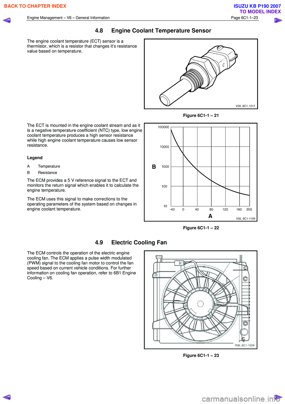
The ECT is mounted in the engine coolant stream and as it
is a negative temperature coefficient (NTC) type, low engine
coolant temperature produces a high sensor resistance
while high engine coolant temperature causes low sensor
resistance.
Legend
A Temperature
B Resistance
The ECM provides a 5 V reference signal to the ECT and
monitors the return signal which enables it to calculate the
engine temperature.
The ECM uses this signal to make corrections to the
operating parameters of the system based on changes in
engine coolant temperature.
Figure 6C1-1 – 22
4.9 Electric Cooling Fan
The ECM controls the operation of the electric engine
cooling fan. The ECM applies a pulse width modulated
(PW M) signal to the cooling fan motor to control the fan
speed based on current vehicle conditions. For further
information on cooling fan operation, refer to 6B1 Engine
Cooling – V6.
Figure 6C1-1 – 23
BACK TO CHAPTER INDEX
TO MODEL INDEX
ISUZU KB P190 2007
Page 3266 of 6020
Engine Management – V6 – General Information Page 6C1-1–24
4.10 Engine Oil Level and Temperature
Sensor
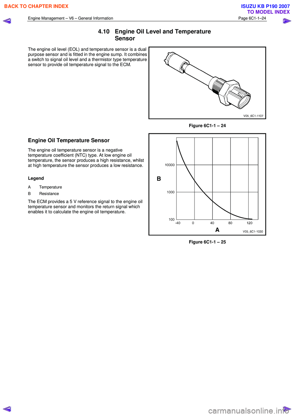
The engine oil level (EOL) and temperature sensor is a dual
purpose sensor and is fitted in the engine sump. It combines
a switch to signal oil level and a thermistor type temperature
sensor to provide oil temperature signal to the ECM.
Figure 6C1-1 – 24
Engine Oil Temperature Sensor
The engine oil temperature sensor is a negative
temperature coefficient (NTC) type. At low engine oil
temperature, the sensor produces a high resistance, whilst
at high temperature the sensor produces a low resistance.
Legend
A Temperature
B Resistance
The ECM provides a 5 V reference signal to the engine oil
temperature sensor and monitors the return signal which
enables it to calculate the engine oil temperature.
Figure 6C1-1 – 25
BACK TO CHAPTER INDEX
TO MODEL INDEX
ISUZU KB P190 2007
Page 3267 of 6020
Engine Management – V6 – General Information Page 6C1-1–25
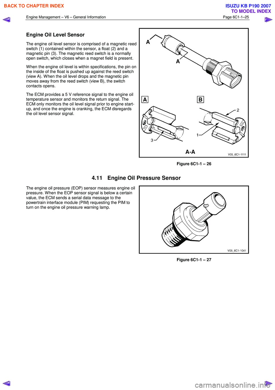
Engine Oil Level Sensor
The engine oil level sensor is comprised of a magnetic reed
switch (1) contained within the sensor, a float (2) and a
magnetic pin (3). The magnetic reed switch is a normally
open switch, which closes when a magnet field is present.
W hen the engine oil level is within specifications, the pin on
the inside of the float is pushed up against the reed switch
(view A). W hen the oil level drops and the magnetic pin
moves away from the reed switch (view B), the switch
contacts opens.
The ECM provides a 5 V reference signal to the engine oil
temperature sensor and monitors the return signal. The
ECM only monitors the oil level signal prior to engine start-
up, and once the engine is cranking, the ECM disregards
the oil level sensor signal.
Figure 6C1-1 – 26
4.11 Engine Oil Pressure Sensor
The engine oil pressure (EOP) sensor measures engine oil
pressure. W hen the EOP sensor signal is below a certain
value, the ECM sends a serial data message to the
powertrain interface module (PIM) requesting the PIM to
turn on the engine oil pressure warning lamp.
Figure 6C1-1 – 27
BACK TO CHAPTER INDEX
TO MODEL INDEX
ISUZU KB P190 2007
Page 3268 of 6020
Engine Management – V6 – General Information Page 6C1-1–26
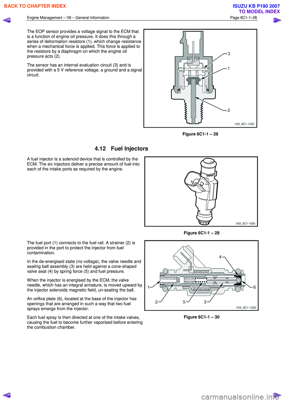
The EOP sensor provides a voltage signal to the ECM that
is a function of engine oil pressure. It does this through a
series of deformation resistors (1), which change resistance
when a mechanical force is applied. This force is applied to
the resistors by a diaphragm on which the engine oil
pressure acts (2).
The sensor has an internal evaluation circuit (3) and is
provided with a 5 V reference voltage, a ground and a signal
circuit.
Figure 6C1-1 – 28
4.12 Fuel Injectors
A fuel injector is a solenoid device that is controlled by the
ECM. The six injectors deliver a precise amount of fuel into
each of the intake ports as required by the engine.
Figure 6C1-1 – 29
The fuel port (1) connects to the fuel rail. A strainer (2) is
provided in the port to protect the injector from fuel
contamination.
In the de-energised state (no voltage), the valve needle and
sealing ball assembly (3) are held against a cone-shaped
valve seat (4) by spring force (5) and fuel pressure.
W hen the injector is energised by the ECM, the valve
needle, which has an integral armature, is moved upward by
the injector solenoids magnetic field, un-seating the ball.
An orifice plate (6), located at the base of the injector has
openings that are arranged in such a way that two fuel
sprays emerge from the injector.
Each fuel spray is then directed at one of the intake valves,
causing the fuel to become further vaporised before entering
the combustion chamber.
Figure 6C1-1 – 30
BACK TO CHAPTER INDEX
TO MODEL INDEX
ISUZU KB P190 2007
Page 3269 of 6020
Engine Management – V6 – General Information Page 6C1-1–27
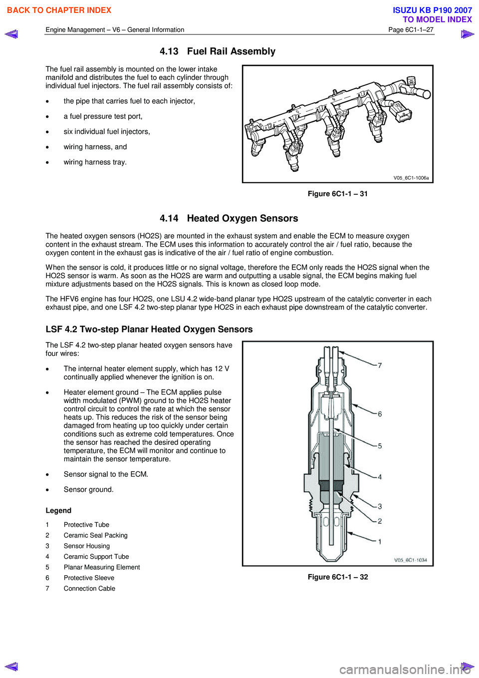
4.13 Fuel Rail Assembly
The fuel rail assembly is mounted on the lower intake
manifold and distributes the fuel to each cylinder through
individual fuel injectors. The fuel rail assembly consists of:
• the pipe that carries fuel to each injector,
• a fuel pressure test port,
• six individual fuel injectors,
• wiring harness, and
• wiring harness tray.
Figure 6C1-1 – 31
4.14 Heated Oxygen Sensors
The heated oxygen sensors (HO2S) are mounted in the exhaust system and enable the ECM to measure oxygen
content in the exhaust stream. The ECM uses this information to accurately control the air / fuel ratio, because the
oxygen content in the exhaust gas is indicative of the air / fuel ratio of engine combustion.
W hen the sensor is cold, it produces little or no signal voltage, therefore the ECM only reads the HO2S signal when the
HO2S sensor is warm. As soon as the HO2S are warm and outputting a usable signal, the ECM begins making fuel
mixture adjustments based on the HO2S signals. This is known as closed loop mode.
The HFV6 engine has four HO2S, one LSU 4.2 wide-band planar type HO2S upstream of the catalytic converter in each
exhaust pipe, and one LSF 4.2 two-step planar type HO2S in each exhaust pipe downstream of the catalytic converter.
LSF 4.2 Two-step Planar Heated Oxygen Sensors
The LSF 4.2 two-step planar heated oxygen sensors have
four wires:
• The internal heater element supply, which has 12 V
continually applied whenever the ignition is on.
• Heater element ground – The ECM applies pulse
width modulated (PW M) ground to the HO2S heater
control circuit to control the rate at which the sensor
heats up. This reduces the risk of the sensor being
damaged from heating up too quickly under certain
conditions such as extreme cold temperatures. Once
the sensor has reached the desired operating
temperature, the ECM will monitor and continue to
maintain the sensor temperature.
• Sensor signal to the ECM.
• Sensor ground.
Legend
1 Protective Tube
2 Ceramic Seal Packing
3 Sensor Housing
4 Ceramic Support Tube
5 Planar Measuring Element
6 Protective Sleeve
7 Connection Cable
Figure 6C1-1 – 32
BACK TO CHAPTER INDEX
TO MODEL INDEX
ISUZU KB P190 2007