2007 ISUZU KB P190 clock
[x] Cancel search: clockPage 3187 of 6020

Engine Cooling – V6 Engine Page 6B1–52
2 Disconnect the transmission cooler pipes from the
transmission.
• Release the verifier disk (2) by pulling back with
the fingers, then slide back down the cooler line
(1).
• Open the cooler line release tool J-41623-B and
slip over cooler line to be disconnected from the
transmission, above the verifier disk (2), as
shown.
• Slide the release tool along the line to engage
with the quick-connect fitting.
• W hile pushing inwards, rotate the tool about one
sixth of a turn to release the spring clip holding
the line.
• W ith the release tool held in this position, pull
back on the cooler line to release.
• Repeat this process with the remaining line and
quick-connect fitting.
3 Plug both pipe openings and hoses to minimise fluid loss and prevent foreign matter entry.
Figure 6B1 –
––
–
59
4 Disconnect the transmission cooler hose/line assemblies from the radiator quick connect fittings as
follows:
• Pull back the verifier disc (1) from the quick
connect fitting (2) and slide it back along the line.
• Open the release tool, Tool No J-41623-B (3),
slip it over the cooler line to be disconnected
from the radiator, ahead of the verifier disc.
• Slide the release tool along the cooler line and
engage it with the quick-connect fitting (2).
• W hile pushing inwards, rotate the release tool
clockwise, about one sixth of a turn to release
the spring clip holding the cooler line.
• W ith the release tool held in this position, pull
back on the cooler line to release it.
• Plug the openings to prevent fluid loss and/or
contamination.
• Repeat the procedure to remove the remaining
cooler line.
NOTE
If the spring clip and/or O-ring seal in the quick-
connect fitting is damaged during the removal
process, the complete fitting must be replaced.
5 Unclip the outlet cooler line (4) from the radiator fan shroud (5).
Figure 6B1 –
––
–
60
BACK TO CHAPTER INDEX
TO MODEL INDEX
ISUZU KB P190 2007
Page 3200 of 6020
Engine Cooling – V6 Engine Page 6B1–65
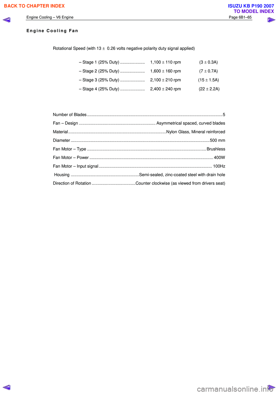
Engine Cooling Fan
Rotational Speed (with 13 ± 0.26 volts negative polarity duty signal applied)
– Stage 1 (25% Duty) ..................... 1,100 ± 110 rpm (3 ± 0.3A)
– Stage 2 (25% Duty) ..................... 1,600 ± 160 rpm (7 ± 0.7A)
– Stage 3 (25% Duty) ..................... 2,100 ± 210 rpm (15 ± 1.5A)
– Stage 4 (25% Duty) ..................... 2,400 ± 240 rpm (22 ± 2.2A)
Number of Blades ............................................................................................................... .... 5
Fan – Design ................................................................. Asymmetrical spaced, curved blades
Material ................................................................................... Nylon Glass, Mineral reinforced
Diameter ...................................................................................................................... 5 00 mm
Fan Motor – Type ..................................................................................................... Brushless
Fan Motor – Power ......................................................................................................... 400W
Fan Motor – Input signal ................................................................................................ 100Hz
Housing ..........................................................Semi-sealed, zinc-coated steel with drain hole
Direction of Rotation .....................................Counter clockwise (as viewed from drivers seat)
BACK TO CHAPTER INDEX
TO MODEL INDEX
ISUZU KB P190 2007
Page 3227 of 6020
Fuel System – V6 Page 6C – 25
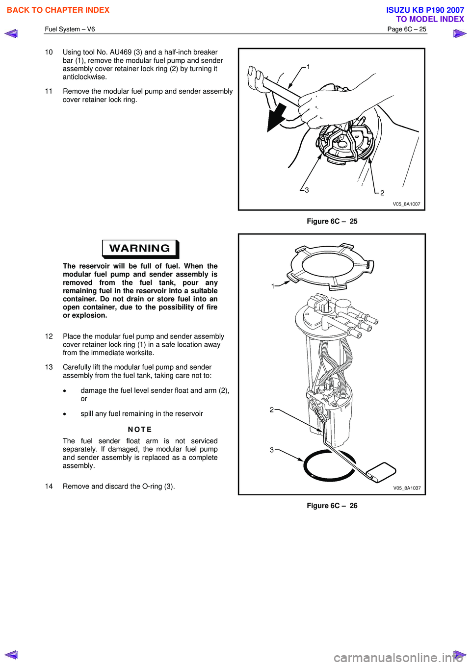
10 Using tool No. AU469 (3) and a half-inch breaker
bar (1), remove the modular fuel pump and sender
assembly cover retainer lock ring (2) by turning it
anticlockwise.
11 Remove the modular fuel pump and sender assembly cover retainer lock ring.
Figure 6C – 25
The reservoir will be full of fuel. When the
modular fuel pump and sender assembly is
removed from the fuel tank, pour any
remaining fuel in the reservoir into a suitable
container. Do not drain or store fuel into an
open container, due to the possibility of fire
or explosion.
12 Place the modular fuel pump and sender assembly cover retainer lock ring (1) in a safe location away
from the immediate worksite.
13 Carefully lift the modular fuel pump and sender assembly from the fuel tank, taking care not to:
• damage the fuel level sender float and arm (2),
or
• spill any fuel remaining in the reservoir
NOTE
The fuel sender float arm is not serviced
separately. If damaged, the modular fuel pump
and sender assembly is replaced as a complete
assembly.
14 Remove and discard the O-ring (3).
Figure 6C – 26
BACK TO CHAPTER INDEX
TO MODEL INDEX
ISUZU KB P190 2007
Page 3228 of 6020
Fuel System – V6 Page 6C – 26
Fuel vapour remains in the fuel tank even
when completely empty. Seal all openings in
the fuel tank using suitable material or a
plastic plug. Ensure no naked flames or other
ignition sources are nearby. Ensure all
cellular phones (and transmission devices
that may cause any metal objects to become
unintentional receiving antennas) are
switched off.
15 Place a suitable material over the opening in the fuel tank to prevent any foreign matter from entering the fuel system.
Fuel Level Sender Assembly
Test
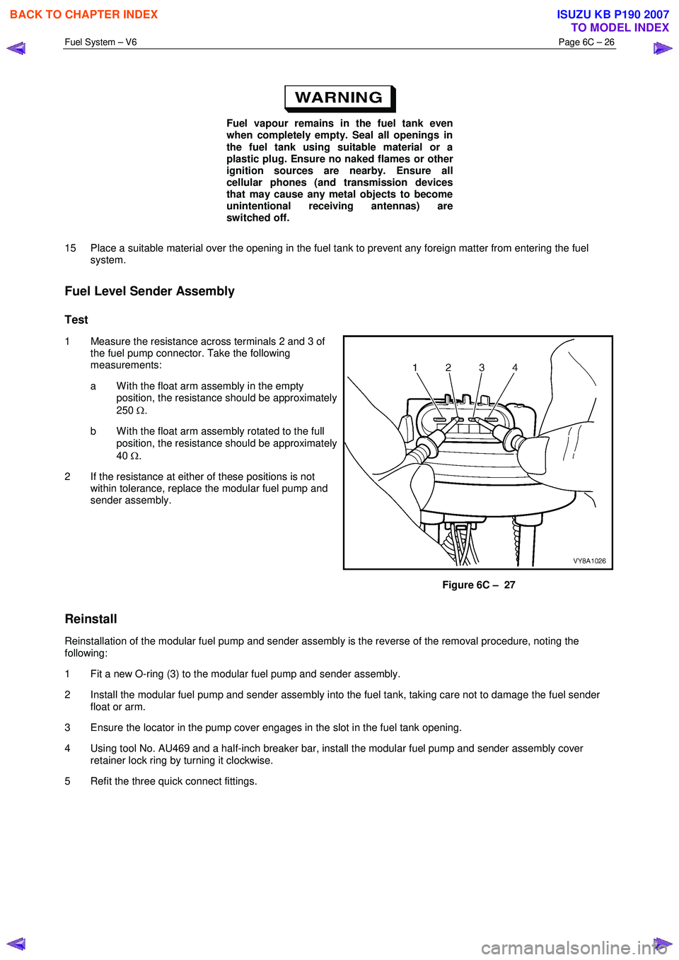
1 Measure the resistance across terminals 2 and 3 of the fuel pump connector. Take the following
measurements:
a W ith the float arm assembly in the empty position, the resistance should be approximately
250 Ω.
b W ith the float arm assembly rotated to the full position, the resistance should be approximately
40 Ω.
2 If the resistance at either of these positions is not within tolerance, replace the modular fuel pump and
sender assembly.
Figure 6C – 27
Reinstall
Reinstallation of the modular fuel pump and sender assembly is the reverse of the removal procedure, noting the
following:
1 Fit a new O-ring (3) to the modular fuel pump and sender assembly.
2 Install the modular fuel pump and sender assembly into the fuel tank, taking care not to damage the fuel sender float or arm.
3 Ensure the locator in the pump cover engages in the slot in the fuel tank opening.
4 Using tool No. AU469 and a half-inch breaker bar, install the modular fuel pump and sender assembly cover retainer lock ring by turning it clockwise.
5 Refit the three quick connect fittings.
BACK TO CHAPTER INDEX
TO MODEL INDEX
ISUZU KB P190 2007
Page 3234 of 6020
Fuel System – V6 Page 6C – 32
4.8 Fuel Filler Cap
The fuel filler cap is a 'screw on' type, with an integrated tightening torque limiting mechanism. W hen installing the fuel
filler cap, tighten it until a ratcheting (clicking) sound is audible, indicating the fuel filler cap is properly tightened. Th e fuel
filler cap is tethered to the fuel filler pocket.
Remove
The fuel filler cap requires a quarter of a turn anticlockwise to be removed.
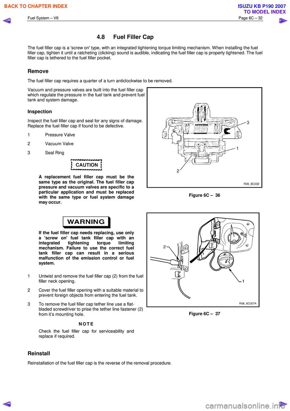
Vacuum and pressure valves are built into the fuel filler cap
which regulate the pressure in the fuel tank and prevent fuel
tank and system damage.
Inspection
Inspect the fuel filler cap and seal for any signs of damage.
Replace the fuel filler cap if found to be defective.
1 Pressure Valve
2 Vacuum Valve
3 Seal Ring
A replacement fuel filler cap must be the
same type as the original. The fuel filler cap
pressure and vacuum valves are specific to a
particular application and must be replaced
with the same type or fuel system damage
may occur.
Figure 6C – 36
If the fuel filler cap needs replacing, use only
a 'screw on' fuel tank filler cap with an
integrated tightening torque limiting
mechanism. Failure to use the correct fuel
tank filler cap can result in a serious
malfunction of the emission control or fuel
system.
1 Untwist and remove the fuel filler cap (2) from the fuel filler neck opening.
2 Cover the fuel filler opening with a suitable material to prevent foreign objects from entering the fuel tank.
3 To remove the fuel filler cap tether line use a flat- bladed screwdriver to prise the tether line fastener (2)
from it’s mounting hole.
NOTE
Check the fuel filler cap for serviceability and
replace if required.
Figure 6C – 37
Reinstall
Reinstallation of the fuel filler cap is the reverse of the removal procedure.
BACK TO CHAPTER INDEX
TO MODEL INDEX
ISUZU KB P190 2007
Page 3602 of 6020

Charging System – V6 Page 6D1-1-15
4 Major Service Operations
4.1 Generator
Remove
Refer to 1.2 WARNING, CAUTION and NOTES
before disconnecting the battery.
1 Disconnect the battery ground lead P-5. Refer to 8A Electrical Body and Chassis.
2 Insert a ½ inch drive socket bar into the tensioner arm and rotate the tensioner arm clockwise.
3 Remove the drive belt from the generator pulley and release the tensioner. Refer to 6A1 Engine Mechanical – V6 for further details as required.
4 Pull the battery harness cap back from generator terminal P-9 (3), remove the nut (4) and remove the
positive lead (2) from the generator (5).
5 Disengage the connector retaining clip and remove the connector E-4, (1) from the generator.
Figure 6D1-1 4
6 Remove the three bolts (1, 2, 4) retaining the generator (3) to the generator bracket.
7 Remove the generator assembly from the vehicle.
Figure 6D1-1 5
BACK TO CHAPTER INDEX
TO MODEL INDEX
ISUZU KB P190 2007
Page 3606 of 6020
Charging System – V6 Page 6D1-1-19
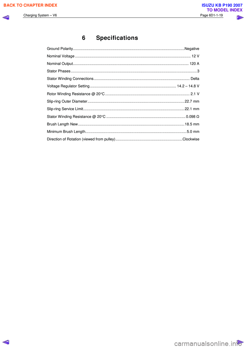
6 Specifications
Ground Polarity...........................................................................................................Negative
Nominal Voltage ............................................................................................................... 1 2 V
Nominal Output............................................................................................................... 12 0 A
Stator Phases .................................................................................................................. ....... 3
Stator W inding Connections ............................................................................................ Delta
Voltage Regulator Setting................................................................................... 14.2 – 14.8 V
Rotor W inding Resistance @ 20 °C ................................................................................. 2.1 V
Slip-ring Outer Diameter ............................................................................................. 22.7 mm
Slip-ring Service Limit ................................................................................................. 22.1 mm
Stator W inding Resistance @ 20 °C ............................................................................ 0.098 Ω
Brush Length New ...................................................................................................... 18.5 mm
Minimum Brush Length................................................................................................. 5.0 mm
Direction of Rotation (viewed from pulley) ................................................................Clockwise
BACK TO CHAPTER INDEX
TO MODEL INDEX
ISUZU KB P190 2007
Page 3638 of 6020
Starting System – V6 Page 6D1-2–30
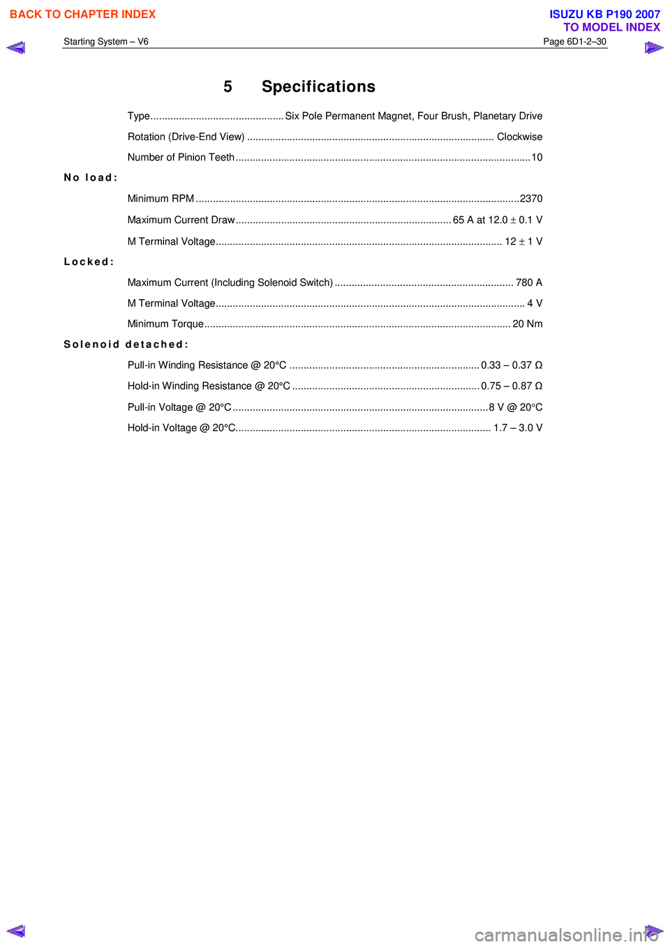
5 Specifications
Type............................................... Six Pole Permanent Magnet, Four Brush, Planetary Drive
Rotation (Drive-End View) ....................................................................................... Clockwise
Number of Pinion Teeth ........................................................................................................ 1 0
No load:
Minimum RPM .................................................................................................................. 23 70
Maximum Current Draw ............................................................................ 65 A at 12.0 ± 0.1 V
M Terminal Voltage..................................................................................................... 12 ± 1 V
Locked:
Maximum Current (Including Solenoid Switch) ............................................................... 780 A
M Terminal Voltage............................................................................................................. 4 V
Minimum Torque ............................................................................................................ 20 Nm
Solenoid detached:
Pull-in Winding Resistance @ 20°C ................................................................... 0.33 – 0.37 Ω
Hold-in Winding Resistance @ 20°C .................................................................. 0.75 – 0.87 Ω
Pull-in Voltage @ 20°C .......................................................................................... 8 V @ 20 °C
Hold-in Voltage @ 20°C.......................................................................................... 1.7 – 3.0 V
BACK TO CHAPTER INDEX
TO MODEL INDEX
ISUZU KB P190 2007