Page 2949 of 6020
Engine Mechanical – V6 Page 6A1–172
Page 6A1–172
2 Using Tool No. EN46111 (1), rotate the crankshaft in
a clockwise direction until the crankshaft sprocket
timing mark (2) is aligned with the indexing mark (3)
on the oil pump housing.
Figure 6A1 – 263
CAUTION
In order to install Tool No. EN 46105 onto the
camshafts, rotate the camshafts. There
should be no need to rotate the camshaft
more than 45 degrees.
Figure 6A1 – 264
3 Install Tool No. EN 46105–1 (1) onto the rear of the right-hand cylinder head camshafts (2).
Figure 6A1 – 265
BACK TO CHAPTER INDEX
TO MODEL INDEX
ISUZU KB P190 2007
Page 2954 of 6020
Engine Mechanical – V6 Page 6A1–177
Page 6A1–177
17 Reset the right-hand secondary timing chain
tensioner.
NOTE
To reset the tensioner, use a suitably sized flat
blade screwdriver (1) or Tool No. J 45027 to
wind the plunger in a clockwise direction, into
the tensioner shaft (2).
Figure 6A1 – 278
18 Install the tensioner s haft (1) into the right-hand
secondary timing chain tensioner body (2).
Figure 6A1 – 279
19 Compress the tensioner shaft into the body and lock the tensioner by inserting Tool No. EN 46112 into the
access hole in the side of the tensioner body.
20 Slowly release pressure on the right-hand secondary timing chain tensioner. The tensioner should remain
compressed.
Figure 6A1 – 280
BACK TO CHAPTER INDEX
TO MODEL INDEX
ISUZU KB P190 2007
Page 2972 of 6020

Engine Mechanical – V6 Page 6A1–195
Page 6A1–195
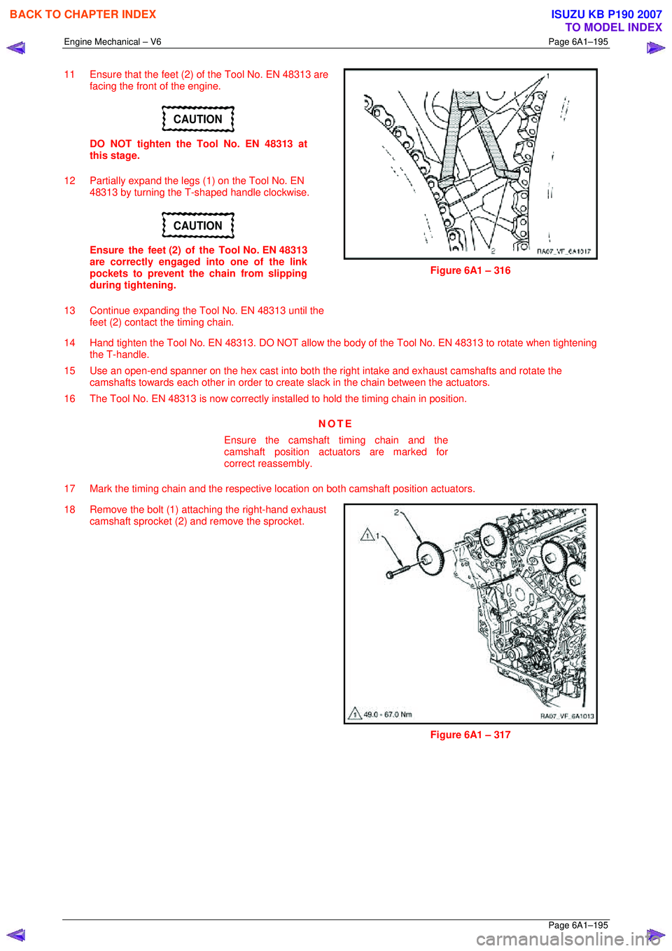
11 Ensure that the feet (2) of the Tool No. EN 48313 are
facing the front of the engine.
CAUTION
DO NOT tighten the Tool No. EN 48313 at
this stage.
12 Partially expand the legs (1) on the Tool No. EN 48313 by turning the T-shaped handle clockwise.
CAUTION
Ensure the feet (2) of the Tool No. EN 48313
are correctly engaged into one of the link
pockets to prevent the chain from slipping
during tightening.
13 Continue expanding the Tool No. EN 48313 until the feet (2) contact the timing chain.
Figure 6A1 – 316
14 Hand tighten the Tool No. EN 48313. DO NOT allow the body of the Tool No. EN 48313 to rotate when tightening
the T-handle.
15 Use an open-end spanner on the hex cast into both the right intake and exhaust camshafts and rotate the
camshafts towards each other in order to creat e slack in the chain between the actuators.
16 The Tool No. EN 48313 is now correctly inst alled to hold the timing chain in position.
NOTE
Ensure the camshaft timing chain and the
camshaft position actuators are marked for
correct reassembly.
17 Mark the timing chain and the respective location on both camshaft position actuators.
18 Remove the bolt (1) attaching the right-hand exhaust camshaft sprocket (2) and remove the sprocket.
Figure 6A1 – 317
BACK TO CHAPTER INDEX
TO MODEL INDEX
ISUZU KB P190 2007
Page 2975 of 6020

Engine Mechanical – V6 Page 6A1–198
Page 6A1–198
11 Ensure that the feet (2) of the Tool No. EN 48313 are
facing the front of the engine.
CAUTION
DO NOT tighten the Tool No. EN 48313 at
this stage.
12 Partially expand the legs (1) on the Tool No. EN 48313 by turning the T-shaped handle clockwise.
CAUTION
Ensure the feet (2) of the Tool No. EN 48313
are correctly engaged into one of the link
pockets to prevent the chain from slipping
during tightening.
Figure 6A1 – 323
13 Continue expanding the Tool No. EN 48313 until the feet (2) contact the timing chain.
14 Hand tighten the Tool No. EN 48313. DO NOT allow the body of the Tool No. EN 48313 to rotate when tightening
the T-handle.
15 Use an open-end spanner on the hex cast into both the left intake and exhaust camshafts and rotate the camshafts
towards each other in order create sla ck in the chain between the actuators.
16 The Tool No. EN 48313 is now correctly inst alled to hold the timing chain in position.
NOTE
Ensure the camshaft timing chain and the
camshaft position actuators are marked for
correct reassembly.
17 Mark the timing chain and the respective location on both camshaft position actuators.
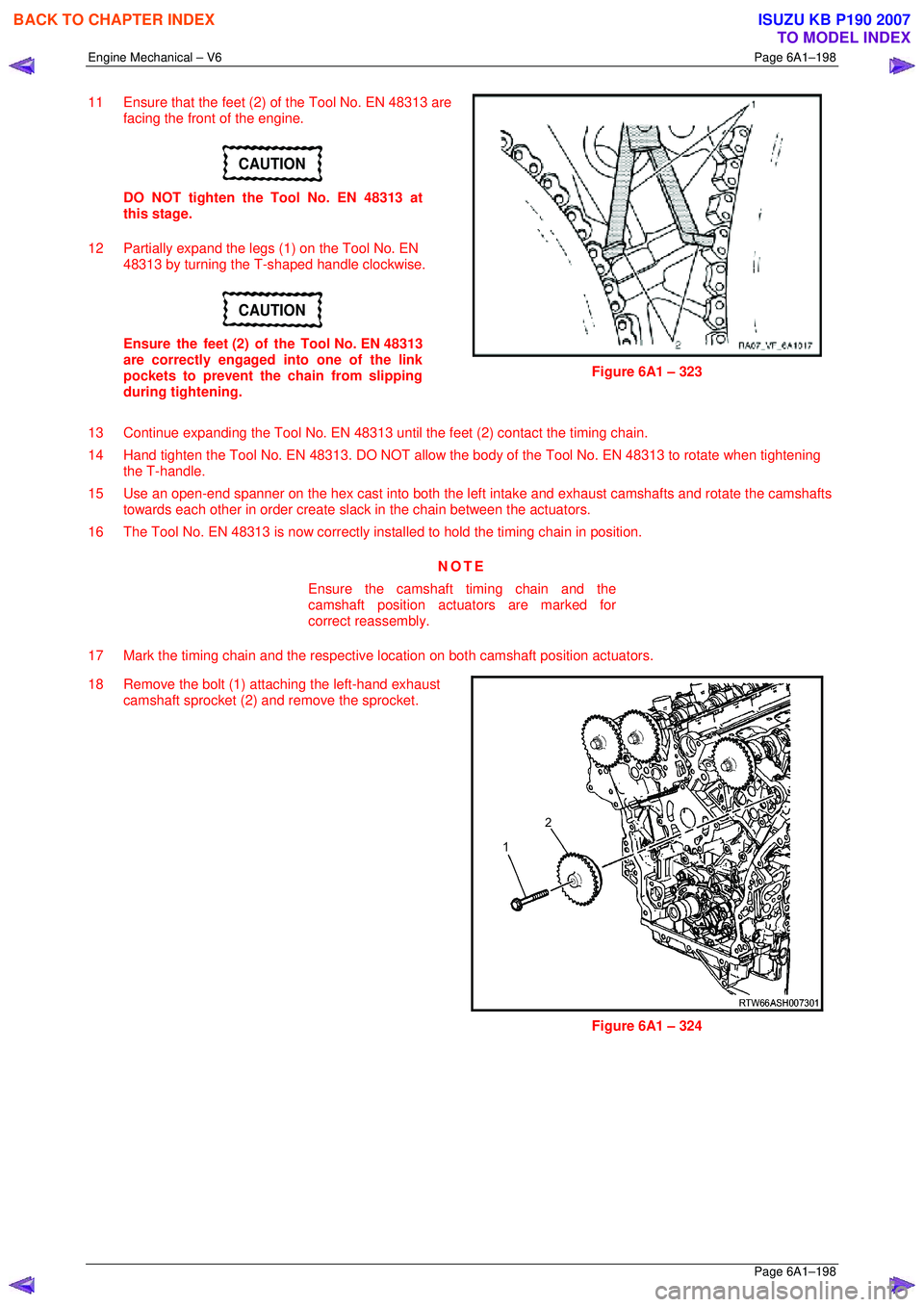
18 Remove the bolt (1) attaching the left-hand exhaust camshaft sprocket (2) and remove the sprocket.
Figure 6A1 – 324
BACK TO CHAPTER INDEX
TO MODEL INDEX
ISUZU KB P190 2007
Page 3025 of 6020
Engine Mechanical – V6 Page 6A1–248
Page 6A1–248
50 Unplug the connector from the oil level sensor (1).
51 Remove the attaching bolt (2) holding the ground cable to the engine block.
Figure 6A1 – 429
52 Remove the accessory drive belt using a socket wrench (1), to reduce tension rotate the drive belt
tensioner (2) clockwise, then while holding the
tensioner in the reduced tens ion position, remove the
accessory drive belt (3).
Figure 6A1 – 430
53 Remove the power steering pump bolts (two places),
remove the pump (1) from the mounting bracket and
disconnect the power steering hoses (two places)
from the pump body.
NOTE
Plug the open ends of the power steering hoses
to prevent the ingre ss of contaminants.
Figure 6A1 – 431
BACK TO CHAPTER INDEX
TO MODEL INDEX
ISUZU KB P190 2007
Page 3143 of 6020

Engine Cooling – V6 Engine Page 6B1–8
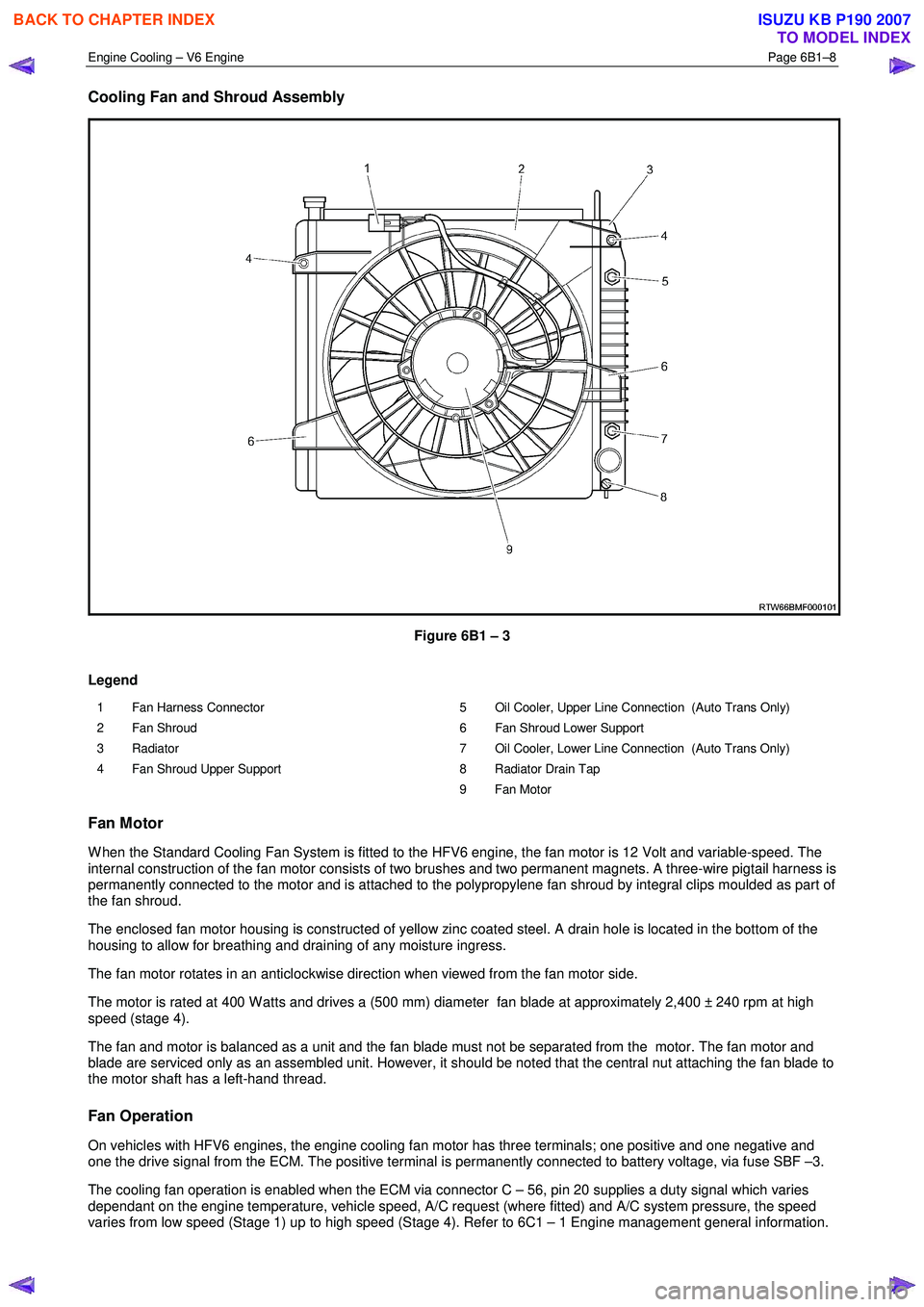
Cooling Fan and Shroud Assembly
Figure 6B1 – 3
Legend
1 Fan Harness Connector
2 Fan Shroud
3 Radiator
4 Fan Shroud Upper Support 5 Oil Cooler, Upper Line Connection (Auto Trans Only)
6 Fan Shroud Lower Support
7 Oil Cooler, Lower Line Connection (Auto Trans Only)
8 Radiator Drain Tap
9 Fan Motor
Fan Motor
W hen the Standard Cooling Fan System is fitted to the HFV6 engine, the fan motor is 12 Volt and variable-speed. The
internal construction of the fan motor consists of two brushes and two permanent magnets. A three-wire pigtail harness is
permanently connected to the motor and is attached to the polypropylene fan shroud by integral clips moulded as part of
the fan shroud.
The enclosed fan motor housing is constructed of yellow zinc coated steel. A drain hole is located in the bottom of the
housing to allow for breathing and draining of any moisture ingress.
The fan motor rotates in an anticlockwise direction when viewed from the fan motor side.
The motor is rated at 400 W atts and drives a (500 mm) diameter fan blade at approximately 2,400 ± 240 rpm at high
speed (stage 4).
The fan and motor is balanced as a unit and the fan blade must not be separated from the motor. The fan motor and
blade are serviced only as an assembled unit. However, it should be noted that the central nut attaching the fan blade to
the motor shaft has a left-hand thread.
Fan Operation
On vehicles with HFV6 engines, the engine cooling fan motor has three terminals; one positive and one negative and
one the drive signal from the ECM. The positive terminal is permanently connected to battery voltage, via fuse SBF –3.
The cooling fan operation is enabled when the ECM via connector C – 56, pin 20 supplies a duty signal which varies
dependant on the engine temperature, vehicle speed, A/C request (where fitted) and A/C system pressure, the speed
varies from low speed (Stage 1) up to high speed (Stage 4). Refer to 6C1 – 1 Engine management general information.
BACK TO CHAPTER INDEX
TO MODEL INDEX
ISUZU KB P190 2007
Page 3151 of 6020

Engine Cooling – V6 Engine Page 6B1–16
3 Service Operations
3.1 Service Notes
Safety
• To avoid serious personal injury, never
remove the coolant filler pressure cap on
the coolant outlet housing when the
engine is hot, even if the cooling system
should require filling. Sudden release of
cooling system pressure is very
dangerous.
• The vehicle is fitted with an electric
radiator cooling fan. When working around
the engine compartment, keep clear of the
fan as it may start without warning.
Before removing the coolant filler cap, allow the engine to cool, then place a shop rag over the coolant filler cap and then
slowly turn the cap anticlockwise, approximately 1½ turns, until the pressure relief position is reached. The pressure
relief position will allow any remaining pressure within the system to escape into the coolant recovery reservoir. Continue
to rotate the cap anticlockwise until the cap can be safely removed.
Periodic Servicing
The cooling system requires little attention except for maintaining the coolant to the correct level in the recovery reservoir
and periodic servicing at the time or distance intervals as outlined in 0B Lubrication and Service.
Periodic servicing includes:
1 Checking coolant level. Refer to 3.3 Draining and Filling Cooling System in this Section.
2 Checking coolant concentration. Refer to 3.2 Coolant Maintenance – Testing Coolant Concentration in this Section.
3 Pressure test cooling system and coolant filler cap. Refer to 3.7 Pressure Testing in this Section.
4 Tighten hose clamps and inspect all hoses. Refer to 3.6 Coolant Hoses in this Section. Replace hoses if swollen or deteriorated.
Always wear protective safety glasses when
working with spring type hose clamps. Failure
to do so could result in eye injury.
5 Clean out cooling system, refer to 3.4 Cleaning Cooling System – Cooling System Flush, in this Section and refill. Refer to 3.3 Draining and Filling Cooling System in this Section.
Environmental Issues
To reduce environmental impact and maintenance cost, whenever the coolant is drained from any engine, the service
records are to be checked to determine when the coolant was last changed. If more than six months life is left before the
next coolant change, then the following procedure is to be followed:
1 W hen draining the coolant from the engine, use a clean container to hold at least 12 litres of coolant and ensure that the coolant is not contaminated in the draining process.
2 After repairs have been completed, refill the engine cooling system with the drained coolant.
BACK TO CHAPTER INDEX
TO MODEL INDEX
ISUZU KB P190 2007
Page 3176 of 6020
Engine Cooling – V6 Engine Page 6B1–41
Figure 6B1 – 42 shows the drive belt routing for the HFV6 engine without air conditioning.
Figure 6B1 – 43
Legend
1 Coolant Pump
2 Generator
3 Idler 4 Power Steering
5 Crankshaft
6 Tensioner
4 Remove the drive belt from the coolant pump pulley:
a Rotate the drive belt tensioner pulley clockwise (arrow) using a 1/2” drive
extension in order to release the drive
belt tension.
b Remove the drive belt from the coolant pump pulley.
c Slowly release the drive belt tensioner.
Figure 6B1 – 44
BACK TO CHAPTER INDEX
TO MODEL INDEX
ISUZU KB P190 2007