2007 ISUZU KB P190 clock
[x] Cancel search: clockPage 3925 of 6020
Automatic Transmission – 4L60E – On-vehicle Servicing Page 7C4–12
4 Remove the knob together with the button (5) and spring (6) from the selector lever assembly (7).
5 Turn the sleeve (8) counter clockwise to remove it, make note of the number of turns required to free it.
6 Remove the harness connectors from the base plate (9).
7 Remove the upper housing (10) which is held in place by four latched fasteners.
8 Remove the attaching screw (11) and spring plate (12).
9 Remove the grooved pin (13).
10 Using a small flat blade screwdriver, gently prise the upper end of the selector cable (14) from the pin on the selector lever linkage (15).
11 Remove the selector lever assembly by pressing the rod down (lever in the N position).
12 If required, remove the lamp (16) from its socket by aligning the groove in the socket and the protruding part of the lamp.
13 If required, remove the nut (17), four places, and the shift selector base plate.
Reinstall
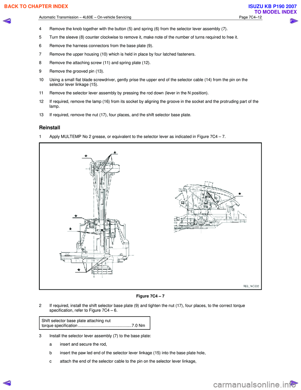
1 Apply MULTEMP No 2 grease, or equivalent to the selector lever as indicated in Figure 7C4 – 7.
Figure 7C4 – 7
2 If required, install the shift selector base plate (9) and tighten the nut (17), four places, to the correct torque specification, refer to Figure 7C4 – 6.
Shift selector base plate attaching nut
torque specification ..............................................7.0 Nm
3 Install the selector lever assembly (7) to the base plate: a insert and secure the rod,
b insert the paw led end of the selector lever linkage (15) into the base plate hole,
c attach the end of the selector cable to the pin on the selector lever linkage,
BACK TO CHAPTER INDEX
TO MODEL INDEX
ISUZU KB P190 2007
Page 3926 of 6020
Automatic Transmission – 4L60E – On-vehicle Servicing Page 7C4–13
d Install the grooved pin (13) in the selector lever.
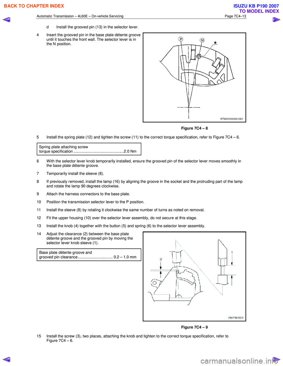
4 Insert the grooved pin in the base plate détente groove until it touches the front wall. The selector lever is in
the N position.
Figure 7C4 – 8
5 Install the spring plate (12) and tighten the screw (11) to the correct torque specification, refer to Figure 7C4 – 6.
Spring plate attaching screw
torque specification ..............................................2.0 Nm
6 W ith the selector lever knob temporarily installed, ensure the grooved pin of the selector lever moves smoothly in the base plate détente groove.
7 Temporarily install the sleeve (8).
8 If previously removed, install the lamp (16) by aligning the groove in the socket and the protruding part of the lamp and rotate the lamp 90 degrees clockwise.
9 Attach the harness connectors to the base plate.
10 Position the transmission selector lever to the P position.
11 Install the sleeve (8) by rotating it clockwise the same number of turns as noted on removal.
12 Fit the upper housing (10) over the selector lever assembly, do not secure at this stage.
13 Install the knob (4) together with the button (5) and spring (6) to the selector lever assembly.
14 Adjust the clearance (2) between the base plate détente groove and the grooved pin by moving the
selector lever knob sleeve (1).
Base plate détente groove and
grooved pin clearance................................ 0.2 – 1.0 mm
Figure 7C4 – 9
15 Install the screw (3), two places, attaching the knob and tighten to the correct torque specification, refer to Figure 7C4 – 6.
BACK TO CHAPTER INDEX
TO MODEL INDEX
ISUZU KB P190 2007
Page 3932 of 6020
Automatic Transmission – 4L60E – On-vehicle Servicing Page 7C4–19
Reinstall
1 Lubricate a new O-ring seal with petroleum jelly and install it to the vehicle speed sensor.
2 Install the speed sensor to the transmission extension housing.
3 Install the attaching bolt and tighten to the correct torque specification.
Vehicle speed sensor attaching bolt
torque specification ............................................ 12.0 Nm
4 Connect the connector to the speed sensor.
5 Lower the vehicle to the ground.
3.6 Manual Shaft Oil Seal
Replace
NOTE
This procedure requires the use of special tool
No. AU583.
1 Raise the vehicle and support in a safe manner, refer to 0A General Information for the location of support points.
2 Remove the neutral start and back-up lamp switch, refer to 3.4 Neutral Start and Back-up Lamp Switch.
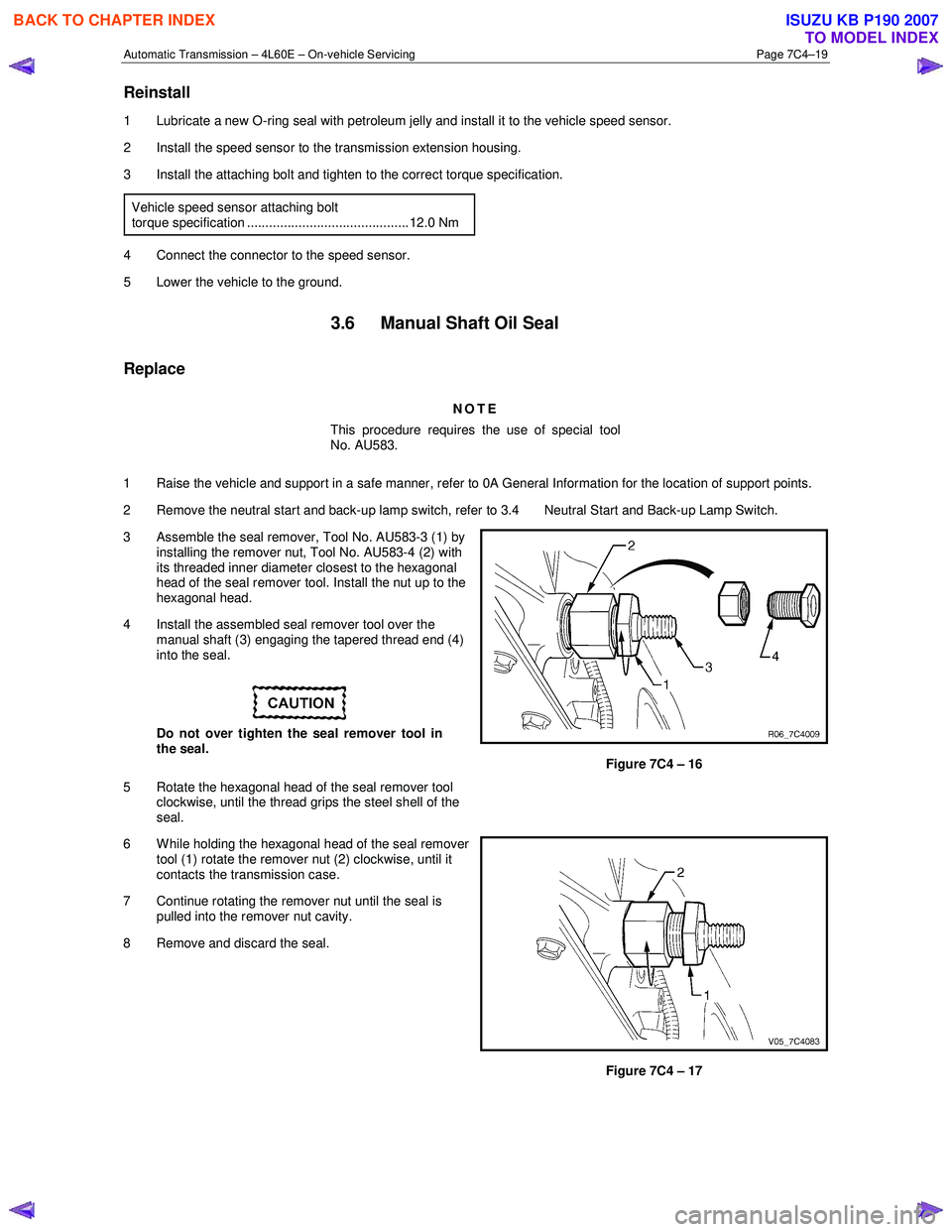
3 Assemble the seal remover, Tool No. AU583-3 (1) by installing the remover nut, Tool No. AU583-4 (2) with
its threaded inner diameter closest to the hexagonal
head of the seal remover tool. Install the nut up to the
hexagonal head.
4 Install the assembled seal remover tool over the manual shaft (3) engaging the tapered thread end (4)
into the seal.
Do not over tighten the seal remover tool in
the seal.
5 Rotate the hexagonal head of the seal remover tool clockwise, until the thread grips the steel shell of the
seal.
Figure 7C4 – 16
6 W hile holding the hexagonal head of the seal remover tool (1) rotate the remover nut (2) clockwise, until it
contacts the transmission case.
7 Continue rotating the remover nut until the seal is pulled into the remover nut cavity.
8 Remove and discard the seal.
Figure 7C4 – 17
BACK TO CHAPTER INDEX
TO MODEL INDEX
ISUZU KB P190 2007
Page 3954 of 6020
Automatic Transmission – 4L60E – On-vehicle Servicing Page 7C4–41
3.17 Transmission Cooler Line/Hose
Assemblies
Remove
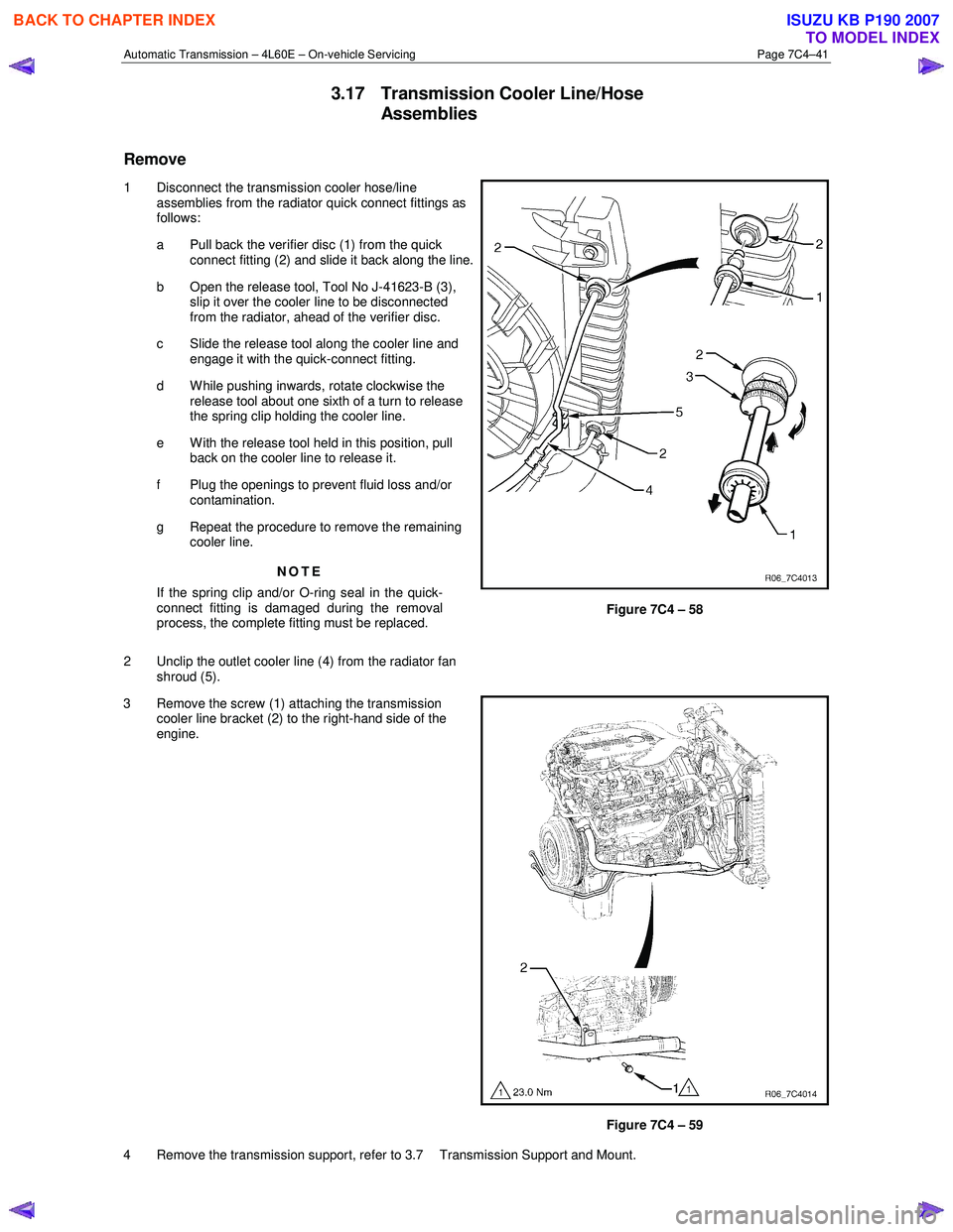
1 Disconnect the transmission cooler hose/line assemblies from the radiator quick connect fittings as
follows:
a Pull back the verifier disc (1) from the quick connect fitting (2) and slide it back along the line.
b Open the release tool, Tool No J-41623-B (3), slip it over the cooler line to be disconnected
from the radiator, ahead of the verifier disc.
c Slide the release tool along the cooler line and engage it with the quick-connect fitting.
d W hile pushing inwards, rotate clockwise the release tool about one sixth of a turn to release
the spring clip holding the cooler line.
e With the release tool held in this position, pull back on the cooler line to release it.
f Plug the openings to prevent fluid loss and/or contamination.
g Repeat the procedure to remove the remaining cooler line.
NOTE
If the spring clip and/or O-ring seal in the quick-
connect fitting is damaged during the removal
process, the complete fitting must be replaced.
2 Unclip the outlet cooler line (4) from the radiator fan shroud (5).
Figure 7C4 – 58
3 Remove the screw (1) attaching the transmission cooler line bracket (2) to the right-hand side of the
engine.
Figure 7C4 – 59
4 Remove the transmission support, refer to 3.7 Transmission Support and Mount.
BACK TO CHAPTER INDEX
TO MODEL INDEX
ISUZU KB P190 2007
Page 3955 of 6020
Automatic Transmission – 4L60E – On-vehicle Servicing Page 7C4–42
5 Carefully lower the rear of the transmission sufficiently to get access to the cooler lines.
6 Place a suitable sized drip tray underneath the transmission.
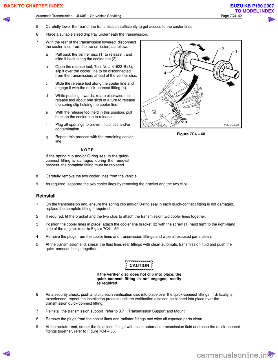
7 W ith the rear of the transmission lowered, disconnect the cooler lines from the transmission, as follows:
a Pull back the verifier disc (1) to release it and slide it back along the cooler line (2).
b Open the release tool, Tool No J-41623-B (3), slip it over the cooler line to be disconnected
from the transmission, ahead of the verifier disc.
c Slide the release tool along the cooler line and engage it with the quick-connect fitting (4).
d W hile pushing inwards, rotate clockwise the release tool about one sixth of a turn to release
the spring clip holding the cooler line.
e With the release tool held in this position, pull back on the cooler line to release it.
f Plug all openings to prevent fluid loss and/or contamination.
g Repeat this process with the remaining cooler line.
NOTE
If the spring clip and/or O-ring seal in the quick-
connect fitting is damaged during the removal
process, the complete fitting must be replaced.
Figure 7C4 – 60
8 Carefully remove the two cooler lines from the vehicle.
9 As required, separate the two cooler lines by removing the bracket and the two clips.
Reinstall
1 On the transmission end, ensure the spring clip and/or O-ring seal in each quick-connect fitting is not damaged, replace the complete fitting if required.
2 If required, fit the bracket and the two clips to attach the transmission two cooler lines together.
3 Position the cooler lines in place, attach the cooler line bracket (2) with the screw (1) hand tight to the right-hand side of the engine, refer to Figure 7C4 – 59.
4 Remove the plugs from the cooler lines and transmission fittings and wipe all exposed parts clean.
5 At the transmission end, smear the fluid lines rear fittings with clean automatic transmission fluid and push the quick-connect fittings together.
If the verifier disc does not clip into place, the
quick-connect fitting is not engaged, rectify
as required.
6 As a security check, push and clip each verification disc into place over the quick-connect fittings. If difficulty is experienced, repeat the installation process until the verification disc can be clipped into place over the
transmission quick-connect fitting.
7 Reinstall the transmission support, refer to 3.7 Transmission Support and Mount.
8 Remove the plugs from the cooler lines and radiator fittings and wipe all exposed parts clean.
9 At the radiator end, smear the fluid lines fittings with clean automatic transmission fluid and push the quick-connect fittings together, refer to Figure 7C4 – 58.
BACK TO CHAPTER INDEX
TO MODEL INDEX
ISUZU KB P190 2007
Page 4111 of 6020
7A3-26 ON-VEHICLE SERVICE (AW30–40LE)
Remove or Disconnect
1. Block the wheels.
2. Disconnect the negative battery cable.
3. Remove the rear console and the front console.
4. Remove the 2 screws fixing the select lever knob.
5. Remove the knob together with the knob button and spring from the lever.
6. Turn the sleeve counterclockwise to remove it. Make a note of the number of turns required to free
the sleeve.
7. Remove the harness connectors from the base plate.
8. Remove the upper housing (held in place by 4 latched fasteners).
9. Remove the lamp assembly by turning it counterclockwise.
10. Remove the spring plate.
11. Remove the grooved pin.
12. Disconnect the shift cable from the select lever.
13. Remove the lever assembly by pressing the rod down (lever in N position).
14. Remove the harness connectors from the shift lock unit, then remove the shift lock unit.
15. Remove the interlock controller.
16. If the replacement of shift lock release button o
r
shift lock button spring is required, remove the
position indicator housing, the shift lock button
spring and shift lock release button can be
removed.
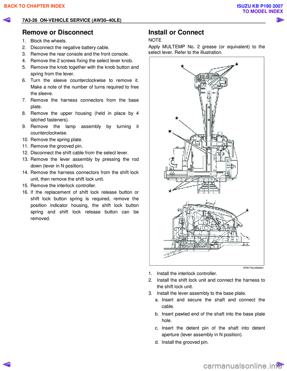
Install or Connect
NOTE
Apply MULTEMP No. 2 grease (or equivalent) to the
select lever. Refer to the illustration.
RTW 77ALH000201
1. Install the interlock controller.
2. Install the shift lock unit and connect the harness to the shift lock unit.
3. Install the lever assembly to the base plate. a. Insert and secure the shaft and connect the cable.
b. Insert pawled end of the shaft into the base plate hole.
c. Insert the detent pin of the shaft into detent aperture (lever assembly in N position).
d. Install the grooved pin.
BACK TO CHAPTER INDEX
TO MODEL INDEX
ISUZU KB P190 2007
Page 4112 of 6020
ON-VEHICLE SERVICE (AW30–40LE) 7A3-27
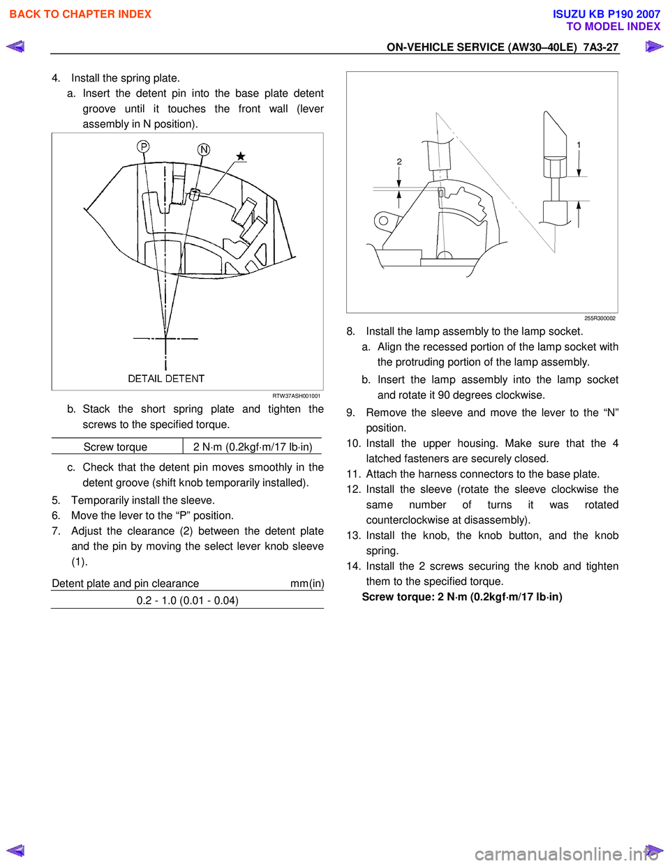
4. Install the spring plate.
a. Insert the detent pin into the base plate detent groove until it touches the front wall (leve
r
assembly in N position).
RTW 37ASH001001
b. Stack the short spring plate and tighten thescrews to the specified torque.
Screw torque 2 N ⋅m (0.2kgf ⋅m/17 lb ⋅in)
c. Check that the detent pin moves smoothly in the
detent groove (shift knob temporarily installed).
5. Temporarily install the sleeve.
6. Move the lever to the “P” position.
7. Adjust the clearance (2) between the detent plate and the pin by moving the select lever knob sleeve
(1).
Detent plate and pin clearance mm(in
)
0.2 - 1.0 (0.01 - 0.04)
255R300002
8. Install the lamp assembly to the lamp socket.
a.
Align the recessed portion of the lamp socket with
the protruding portion of the lamp assembly.
b. Insert the lamp assembly into the lamp socket and rotate it 90 degrees clockwise.
9. Remove the sleeve and move the lever to the “N” position.
10. Install the upper housing. Make sure that the 4 latched fasteners are securely closed.
11. Attach the harness connectors to the base plate.
12. Install the sleeve (rotate the sleeve clockwise the same number of turns it was rotated
counterclockwise at disassembly).
13. Install the knob, the knob button, and the knob spring.
14. Install the 2 screws securing the knob and tighten them to the specified torque.
Screw torque: 2 N ⋅
⋅⋅
⋅
m (0.2kgf ⋅
⋅⋅
⋅
m/17 lb ⋅
⋅⋅
⋅
in)
BACK TO CHAPTER INDEX
TO MODEL INDEX
ISUZU KB P190 2007
Page 4161 of 6020
7A4–26 UNIT REPAIR (AW30–40LE)
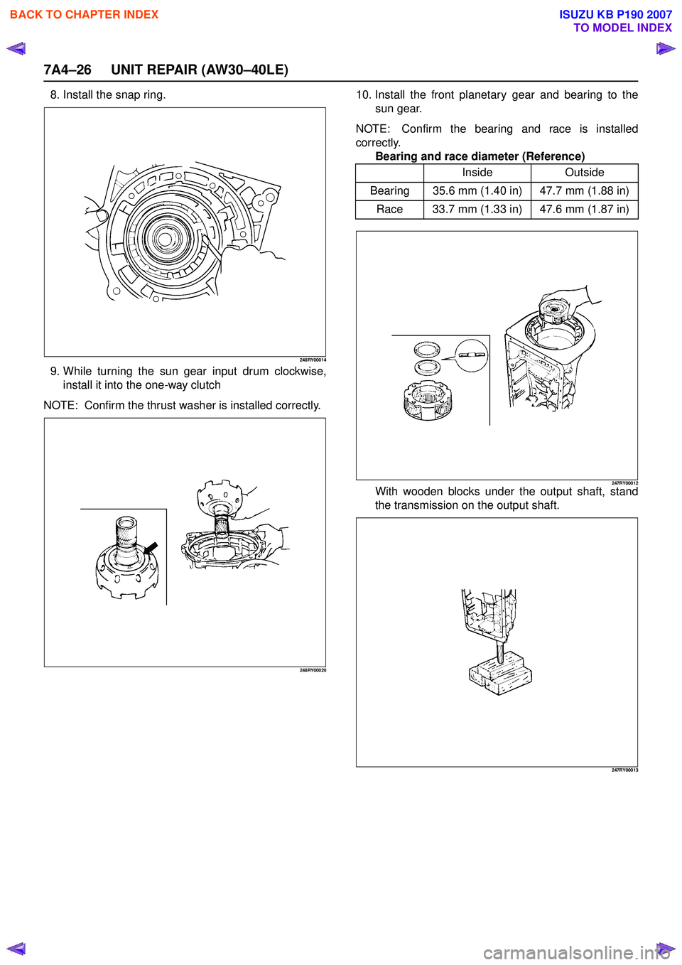
8. Install the snap ring.
248RY00014
9. While turning the sun gear input drum clockwise,install it into the one-way clutch
NOTE: Confirm the thrust washer is installed correctly.
248RY00020
10. Install the front planetary gear and bearing to the sun gear.
NOTE: Confirm the bearing and race is installed
correctly. Bearing and race diameter (Reference)
247RY00012With wooden blocks under the output shaft, stand
the transmission on the output shaft.
247RY00013
Inside Outside
Bearing 35.6 mm (1.40 in) 47.7 mm (1.88 in) Race 33.7 mm (1.33 in) 47.6 mm (1.87 in)
BACK TO CHAPTER INDEX
TO MODEL INDEX
ISUZU KB P190 2007