2007 ISUZU KB P190 clock
[x] Cancel search: clockPage 4449 of 6020
TRANSMISSION CONTROL SYSTEM (JR405E) 7A2-165
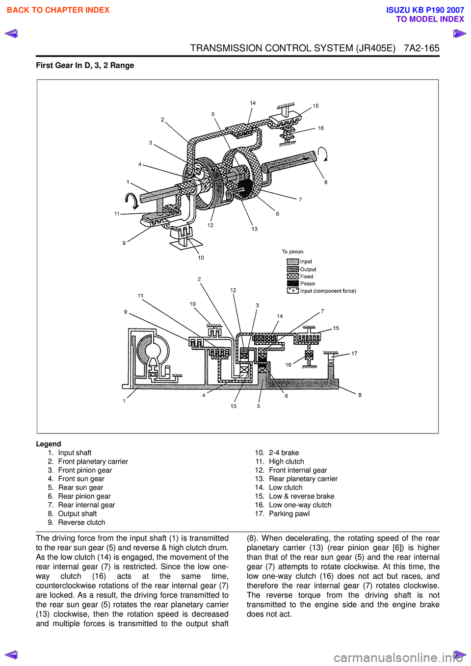
First Gear In D, 3, 2 Range
Legend1. Input shaft
2. Front planetary carrier
3. Front pinion gear
4. Front sun gear
5. Rear sun gear
6. Rear pinion gear
7. Rear internal gear
8. Output shaft
9. Reverse clutch 10. 2-4 brake
11. High clutch
12. Front internal gear
13. Rear planetary carrier
14. Low clutch
15. Low & reverse brake
16. Low one-way clutch
17. Parking pawl
The driving force from the input shaft (1) is transmitted
to the rear sun gear (5) and reverse & high clutch drum.
As the low clutch (14) is engaged, the movement of the
rear internal gear (7) is restricted. Since the low one-
way clutch (16) acts at the same time,
counterclockwise rotations of the rear internal gear (7)
are locked. As a result, the driving force transmitted to
the rear sun gear (5) rotates the rear planetary carrier
(13) clockwise, then the rotation speed is decreased
and multiple forces is transmitted to the output shaft (8). When decelerating, the rotating speed of the rear
planetary carrier (13) (rear pinion gear [6]) is higher
than that of the rear sun gear (5) and the rear internal
gear (7) attempts to rotate clockwise. At this time, the
low one-way clutch (16) does not act but races, and
therefore the rear internal gear (7) rotates clockwise.
The reverse torque from the driving shaft is not
transmitted to the engine side and the engine brake
does not act.
BACK TO CHAPTER INDEX
TO MODEL INDEX
ISUZU KB P190 2007
Page 4451 of 6020
TRANSMISSION CONTROL SYSTEM (JR405E) 7A2-167
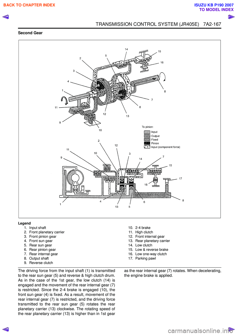
Second Gear
Legend1. Input shaft
2. Front planetary carrier
3. Front pinion gear
4. Front sun gear
5. Rear sun gear
6. Rear pinion gear
7. Rear internal gear
8. Output shaft
9. Reverse clutch 10. 2-4 brake
11. High clutch
12. Front internal gear
13. Rear planetary carrier
14. Low clutch
15. Low & reverse brake
16. Low one-way clutch
17. Parking pawl
The driving force from the input shaft (1) is transmitted
to the rear sun gear (5) and reverse & high clutch drum.
As in the case of the 1st gear, the low clutch (14) is
engaged and the movement of the rear internal gear (7)
is restricted. Since the 2-4 brake is engaged (10), the
front sun gear (4) is fixed. As a result, movement of the
rear internal gear (7) is restricted, and the driving force
transmitted to the rear sun gear (5) rotates the rear
planetary carrier (13) clockwise. The rotating speed of
the rear planetary carrier (13) is higher than in 1st gear as the rear internal gear (7) rotates. When decelerating,
the engine brake is applied.
BACK TO CHAPTER INDEX
TO MODEL INDEX
ISUZU KB P190 2007
Page 4453 of 6020

TRANSMISSION CONTROL SYSTEM (JR405E) 7A2-169
Fourth Gear
Legend1. Input shaft
2. Front planetary carrier
3. Front pinion gear
4. Front sun gear
5. Rear sun gear
6. Rear pinion gear
7. Rear internal gear
8. Output shaft
9. Reverse clutch 10. 2-4 brake
11. High clutch
12. Front internal gear
13. Rear planetary carrier
14. Low clutch
15. Low & reverse brake
16. Low one-way clutch
17. Parking pawl
The driving force from the input shaft (1) is transmitted
to the rear sun gear (5) and reverse & high clutch drum.
Since the 2-4 brake (10) is engaged, the front sun gear
(4) is fixed. In addition to this the high clutch (11) is
engaged. As a result, the front pinion gear (6) rotates
itself together with other gears clockwise. This rotation
increases the speed of rotation of the front internal gear
(12) and is transmitted to the output shaft (8).
BACK TO CHAPTER INDEX
TO MODEL INDEX
ISUZU KB P190 2007
Page 4465 of 6020
ON-VEHICLE SERVICE (JR405E) 7A3-11
Remove or Disconnect
1. Block the wheels.
2. Disconnect the negative battery cable.
3. Remove the rear console and the front console.
4. Remove the 2 screws fixing the select lever knob.
5. Remove the knob together with the knob button and spring from the lever.
6. Turn the sleeve counterclockwise to remove it. Make a note of the number of turns required to free
the sleeve.
7. Remove the harness connectors from the base plate.
8. Remove the upper housing (held in place by 4 latched fasteners).
9. Remove the lamp assembly by turning it counterclockwise.
10. Remove the spring plate.
11. Remove the grooved pin.
12. Disconnect the shift cable from the select lever.
13. Remove the lever assembly by pressing the rod down (lever in N position).
14. Remove the harness connectors from the shift lock unit, then remove the shift lock unit.
15. Remove the interlock controller.
16. If the replacement of shift lock release button o
r
shift lock button spring is required, remove the
position indicator housing, the shift lock button
spring and shift lock release button can be
removed.
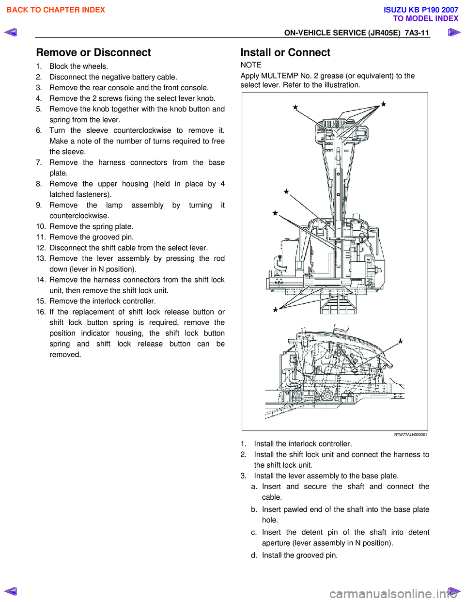
Install or Connect
NOTE
Apply MULTEMP No. 2 grease (or equivalent) to the
select lever. Refer to the illustration.
RTW 77ALH000201
1. Install the interlock controller.
2. Install the shift lock unit and connect the harness to the shift lock unit.
3. Install the lever assembly to the base plate. a. Insert and secure the shaft and connect the cable.
b. Insert pawled end of the shaft into the base plate hole.
c. Insert the detent pin of the shaft into detent aperture (lever assembly in N position).
d. Install the grooved pin.
BACK TO CHAPTER INDEX
TO MODEL INDEX
ISUZU KB P190 2007
Page 4466 of 6020
7A3-12 ON-VEHICLE SERVICE (JR405E)
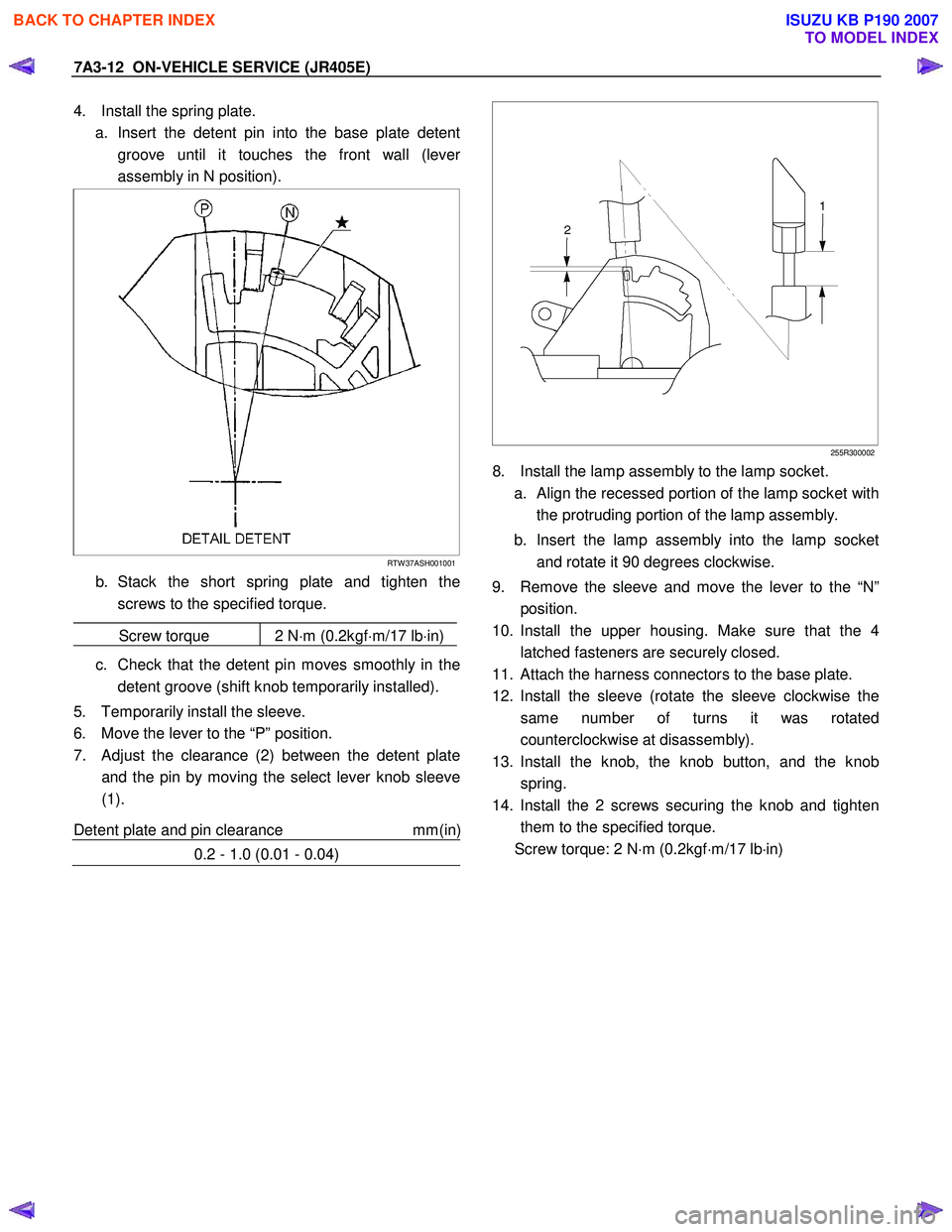
4. Install the spring plate.
a. Insert the detent pin into the base plate detent groove until it touches the front wall (leve
r
assembly in N position).
RTW 37ASH001001
b. Stack the short spring plate and tighten thescrews to the specified torque.
Screw torque 2 N ⋅m (0.2kgf ⋅m/17 lb ⋅in)
c. Check that the detent pin moves smoothly in the
detent groove (shift knob temporarily installed).
5. Temporarily install the sleeve.
6. Move the lever to the “P” position.
7. Adjust the clearance (2) between the detent plate and the pin by moving the select lever knob sleeve
(1).
Detent plate and pin clearance mm(in
)
0.2 - 1.0 (0.01 - 0.04)
255R300002
8. Install the lamp assembly to the lamp socket.
a.
Align the recessed portion of the lamp socket with
the protruding portion of the lamp assembly.
b. Insert the lamp assembly into the lamp socket and rotate it 90 degrees clockwise.
9. Remove the sleeve and move the lever to the “N” position.
10. Install the upper housing. Make sure that the 4 latched fasteners are securely closed.
11. Attach the harness connectors to the base plate.
12. Install the sleeve (rotate the sleeve clockwise the same number of turns it was rotated
counterclockwise at disassembly).
13. Install the knob, the knob button, and the knob spring.
14. Install the 2 screws securing the knob and tighten them to the specified torque.
Screw torque: 2 N ⋅m (0.2kgf ⋅m/17 lb ⋅in)
BACK TO CHAPTER INDEX
TO MODEL INDEX
ISUZU KB P190 2007
Page 4525 of 6020
7A4-48 UNIT REPAIR (JR405E)
25C&L-SUB27
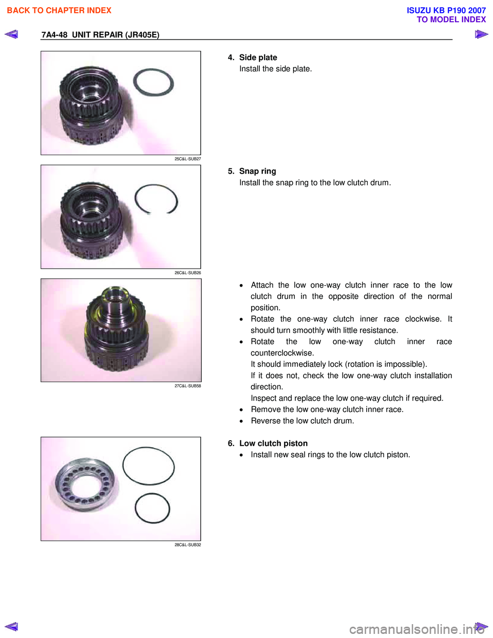
4. Side plate
Install the side plate.
26C&L-SUB26
5. Snap ring
Install the snap ring to the low clutch drum.
27C&L-SUB58
•
Attach the low one-way clutch inner race to the low
clutch drum in the opposite direction of the normal
position.
• Rotate the one-way clutch inner race clockwise. It
should turn smoothly with little resistance.
• Rotate the low one-way clutch inner race
counterclockwise.
It should immediately lock (rotation is impossible).
If it does not, check the low one-way clutch installation
direction.
Inspect and replace the low one-way clutch if required.
• Remove the low one-way clutch inner race.
• Reverse the low clutch drum.
28C&L-SUB32
6. Low clutch piston
• Install new seal rings to the low clutch piston.
BACK TO CHAPTER INDEX
TO MODEL INDEX
ISUZU KB P190 2007
Page 4809 of 6020
CLUTCH 7C-31
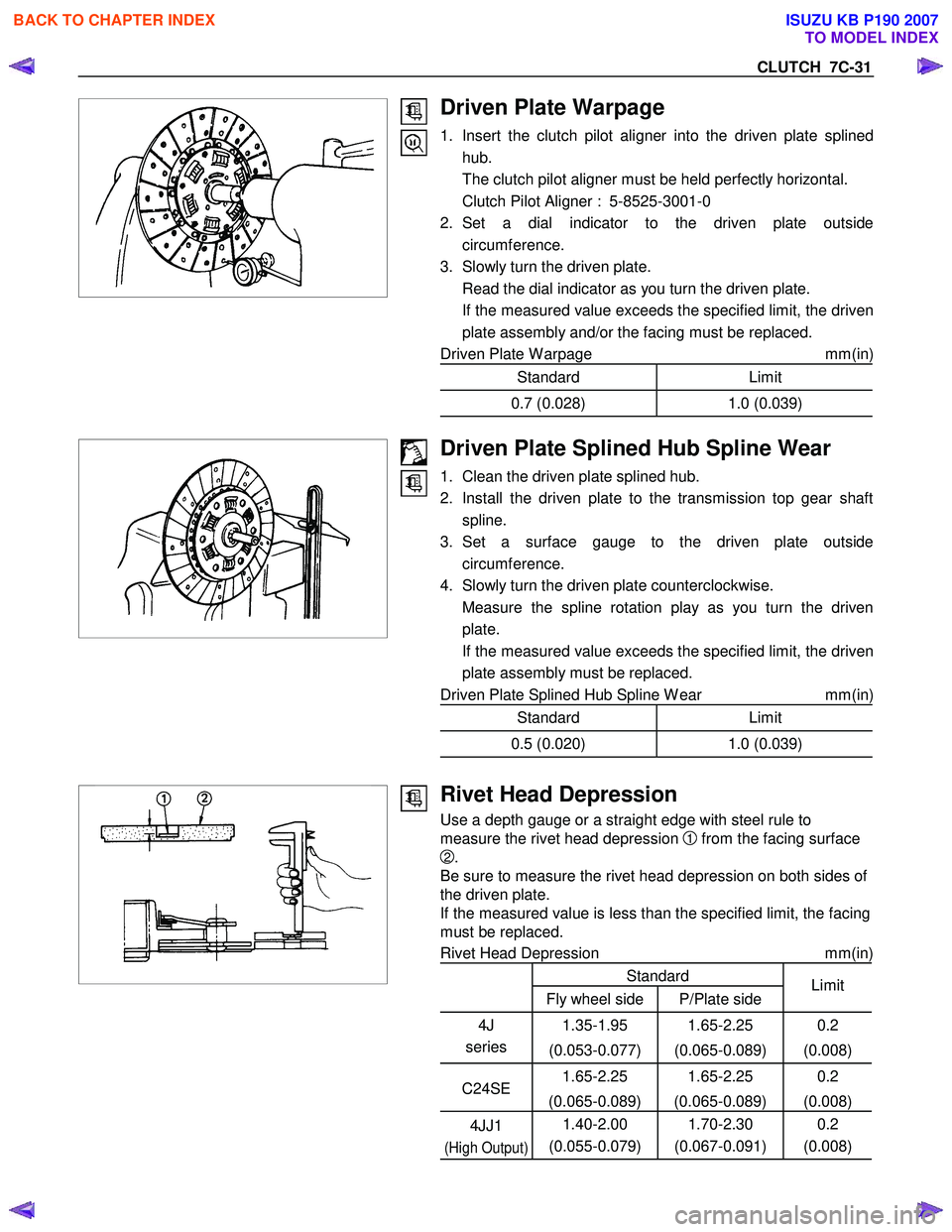
Driven Plate Warpage
1. Insert the clutch pilot aligner into the driven plate splinedhub.
The clutch pilot aligner must be held perfectly horizontal.
Clutch Pilot Aligner : 5-8525-3001-0
2. Set a dial indicator to the driven plate outside circumference.
3. Slowly turn the driven plate.
Read the dial indicator as you turn the driven plate.
If the measured value exceeds the specified limit, the driven plate assembly and/or the facing must be replaced.
Driven Plate W arpage mm(in)
Standard Limit
0.7 (0.028)1.0 (0.039)
Driven Plate Splined Hub Spline Wear
1. Clean the driven plate splined hub.
2. Install the driven plate to the transmission top gear shaft spline.
3. Set a surface gauge to the driven plate outside circumference.
4. Slowly turn the driven plate counterclockwise.
Measure the spline rotation play as you turn the driven plate.
If the measured value exceeds the specified limit, the driven plate assembly must be replaced.
Driven Plate Splined Hub Spline W ear mm(in)
Standard Limit
0.5 (0.020)1.0 (0.039)
Rivet Head Depression
Use a depth gauge or a straight edge with steel rule to
measure the rivet head depression
1 from the facing surface
2.
Be sure to measure the rivet head depression on both sides of
the driven plate.
If the measured value is less than the specified limit, the facing
must be replaced.
Rivet Head Depression mm(in)
Standard
Fly wheel side P/Plate side Limit
4J
series 1.35-1.95
(0.053-0.077) 1.65-2.25
(0.065-0.089) 0.2
(0.008)
C24SE 1.65-2.25
(0.065-0.089) 1.65-2.25
(0.065-0.089) 0.2
(0.008)
4JJ1
(High Output)
1.40-2.00
(0.055-0.079) 1.70-2.30
(0.067-0.091) 0.2
(0.008)
BACK TO CHAPTER INDEX
TO MODEL INDEX
ISUZU KB P190 2007
Page 4941 of 6020
ELECTRICAL-BODY AND CHASSIS 8A-3
PAGE
Power Window ............................................................................................................8A- 41 5
Audio, Clock and Cigarette Lighter ...........................................................................8A- 440
Power Door Mirror ......................................................................................................8A- 464
Rear Defogger .............................................................................................................8A- 480
Supplemental Restraint System (SRS)-Air Bag ........................................................8A- 491
Transfer Case Control Module ...................................................................................8A- 498
Anti-Lock Brake System .............................................................................................8A- 514
Immobilizer ..................................................................................................................8 A- 519
Keyless Entry ..............................................................................................................8A- 529
Data Link Connector ...................................................................................................8A- 553
Anti Theft ..................................................................................................................... .8A- 561
Key Inter Lock .............................................................................................................8A- 588
DRM ........................................................................................................................... ...8A- 592
Trailer Hitch ................................................................................................................. 8A- 595
Power Train Interface Module (PIM) ..........................................................................8A- 600
Connector List ................................................................................................................ .8A- 606
BACK TO CHAPTER INDEX
TO MODEL INDEX
ISUZU KB P190 2007