Page 5174 of 6020
8A-236 ELECTRICAL-BODY AND CHASSIS
HIGH MOUNTED STOPLIGHT
Remove the bulb socket
1. Remove the high mounted stoplight ASM. • Remove the screws.
• Disconnect the connector.
2. Remove the bulb socket.
• Turn the bulb
1 counterclockwise to remove it.
Installation
Follow the removal procedure in the reverse order to install the
rear combination light.
Pay close attention to the important points mentioned in the
following paragraphs.
Bulb
Be absolutely sure that each bulb is correctly installed.
This will prevent a poor contact and an open circuit.
DOOR MIRROR - TURN SIGNAL LIGHT
Removal
1. Pull the lower outside corner of the mirror toward you.
RUW 580SH000701
2. Press the blade of an ordinary screwdriver (2) into the
mirror outside groove near the mirror base hole (1).
BACK TO CHAPTER INDEX TO MODEL INDEXISUZU KB P190 2007
Page 5175 of 6020

ELECTRICAL-BODY AND CHASSIS 8A-237
RUW 580SH000801
3. Turn the blade of the screwdriver 90 degrees to separate
the parts (1).
RUW 580SH000901
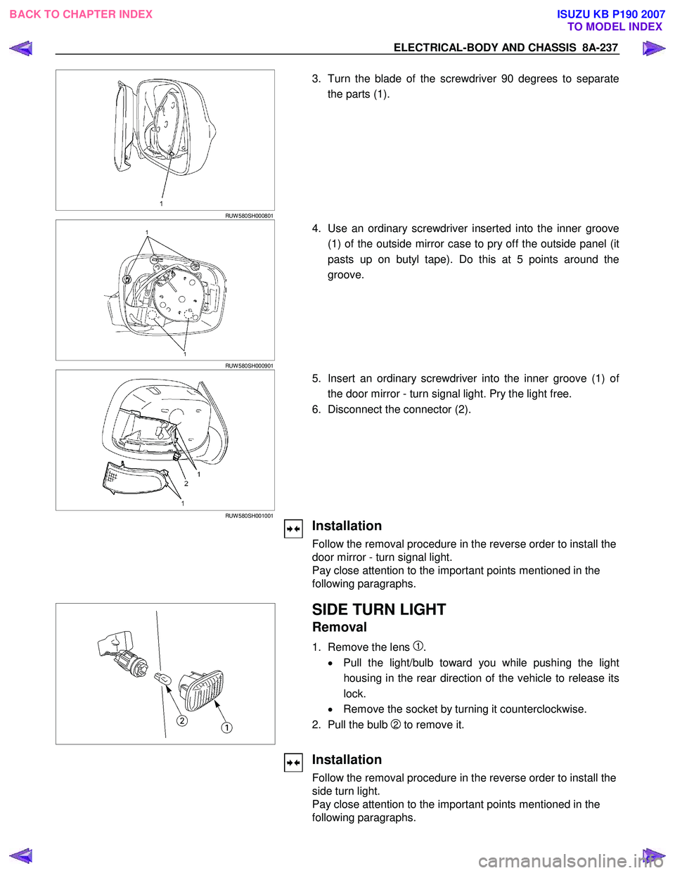
4. Use an ordinary screwdriver inserted into the inner groove
(1) of the outside mirror case to pry off the outside panel (it
pasts up on butyl tape). Do this at 5 points around the
groove.
RUW 580SH001001
5. Insert an ordinary screwdriver into the inner groove (1) of
the door mirror - turn signal light. Pry the light free.
6. Disconnect the connector (2).
Installation
Follow the removal procedure in the reverse order to install the
door mirror - turn signal light.
Pay close attention to the important points mentioned in the
following paragraphs.
SIDE TURN LIGHT
Removal
1. Remove the lens 1.
• Pull the light/bulb toward you while pushing the light
housing in the rear direction of the vehicle to release its
lock.
• Remove the socket by turning it counterclockwise.
2. Pull the bulb
2 to remove it.
Installation
Follow the removal procedure in the reverse order to install the
side turn light.
Pay close attention to the important points mentioned in the
following paragraphs.
BACK TO CHAPTER INDEX TO MODEL INDEXISUZU KB P190 2007
Page 5176 of 6020
8A-238 ELECTRICAL-BODY AND CHASSIS
Bulb
Be absolutely sure that the side turn light bulb is correctly
installed.
This will prevent a poor contact and an open circuit.
A Type
RTW 780SH002101
REAR COMBINATION LIGHT
Turn Signal Light
Removal
1. Open the tail gate.
2. Remove the screws.
3. Remove the rear combination light assembly.
B Type
RTW 580SH000401
A Type
RTW 780SH001301
4. Turn the bulb 1 counterclockwise to remove it.
B Type
RTW 78ASH002501
Installation
Follow the removal procedure in the reverse order to install the
rear combination light.
Pay close attention to the important points mentioned in the
following paragraphs.
BACK TO CHAPTER INDEX TO MODEL INDEXISUZU KB P190 2007
Page 5178 of 6020
8A-240 ELECTRICAL-BODY AND CHASSIS
B Type
RTW 580SH000401
A Type
RTW 780SH001401
4. Turn the bulb 1 counterclockwise to remove it.
B Type
RTW 78ASH002601
Installation
Follow the removal procedure in the reverse order to install the
rear combination light.
Pay close attention to the important points mentioned in the
following paragraphs.
Bulbs
Be absolutely sure that each bulb is correctly installed.
This will prevent a poor contact and an open circuit.
RTW 780SH001501
This illustration is based on RHD model
HAZARD WARNING FLASHER SWITCH
Removal
1. Disconnect the battery ground cable.
2. Instrument Panel Cluster Assembly • Refer to Section 10 “BODY” for instrument panel cluste
r
assembly removal steps.
3. Hazard W arning Switch • Disconnect the switch connector.
• To remove the switch, push the lock from the back side
of the cluster assembly.
BACK TO CHAPTER INDEX TO MODEL INDEXISUZU KB P190 2007
Page 5199 of 6020
ELECTRICAL-BODY AND CHASSIS 8A-261
DOOR SWITCH
Removal
1. Disconnect the battery ground cable.
2. Loosen the screw
1.
3. Remove the door switch
2.
4. Disconnect the door switch connector
3.
Installation
Follow the removal procedure in the reverse order to install the
spot light.
Pay close attention to the important points mentioned in the
following paragraphs.
Connector
Be absolutely sure that the door switch connector is securely
connected.
This will prevent a poor contact and an open circuit.
SPOTLIGHT (MAP Light)
Removal
1. Grasp the spotlight housing 1 with both hands.
Pull the housing straight down.
This will release the clip.
2. Disconnect the connector
2.
3. Turn socket
3 counterclockwise to remove it.
BACK TO CHAPTER INDEX TO MODEL INDEXISUZU KB P190 2007
Page 5200 of 6020

8A-262 ELECTRICAL-BODY AND CHASSIS
Installation
Follow the removal procedure in the reverse order to install the
spot light.
Pay close attention to the important points mentioned in the
following paragraphs.
Connector
Be absolutely sure that the spot light connector is securely
connected.
This will prevent a poor contact and an open circuit.
Bulb
Be absolutely sure that the spot light bulb is correctly installed.
This will prevent a poor contact and an open circuit.
RUW 580SH001501
RUW 580SH001601
OVER HEAD CONSOLE (MAP Light)
Removal
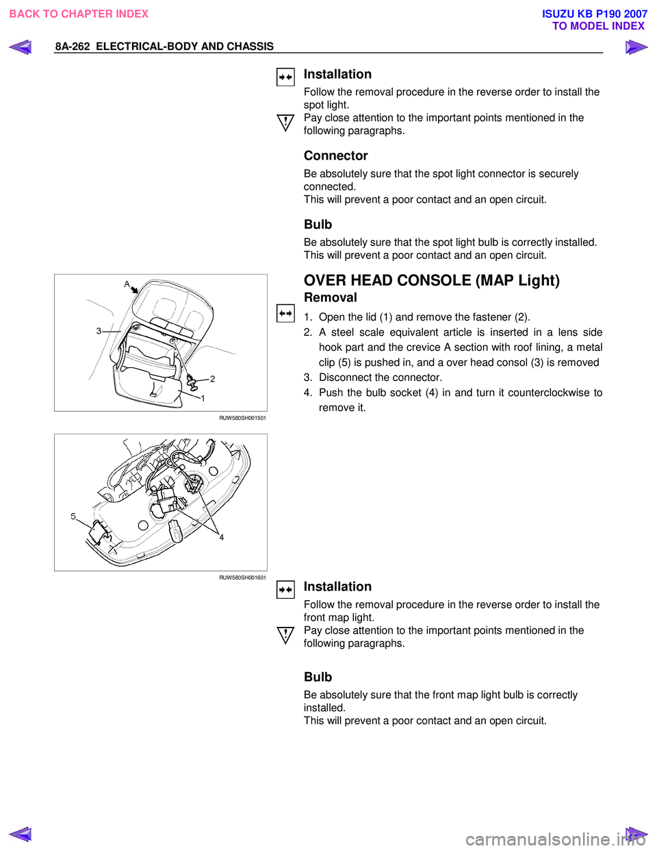
1. Open the lid (1) and remove the fastener (2).
2. A steel scale equivalent article is inserted in a lens side hook part and the crevice A section with roof lining, a metal
clip (5) is pushed in, and a over head consol (3) is removed
3. Disconnect the connector.
4. Push the bulb socket (4) in and turn it counterclockwise to remove it.
Installation
Follow the removal procedure in the reverse order to install the
front map light.
Pay close attention to the important points mentioned in the
following paragraphs.
Bulb
Be absolutely sure that the front map light bulb is correctly
installed.
This will prevent a poor contact and an open circuit.
BACK TO CHAPTER INDEX TO MODEL INDEXISUZU KB P190 2007
Page 5378 of 6020
8A-440 ELECTRICAL-BODY AND CHASSIS
AUDIO, CLOCK AND CIGARETTE LIGHTER
PARTS LOCATION (RHD)
RTW 78AXF039701 & RTW 78AXF045901
BACK TO CHAPTER INDEX
TO MODEL INDEXISUZU KB P190 2007
Page 5544 of 6020
8A-606 ELECTRICAL-BODY AND CHASSIS
CONNECTOR LIST
No. Connector face No. Connector face
B1
~
B6 NOT USED B16
(
HFV6
4JH1-TC
)
White
Hazard switch
B7
Black
Rear defogger relay B16
(4JJ1-TC
4JA1T-(L))
Gray Hazard switch
B8
Black
Power window relay B17
~
B19 NOT USED
B9
NOT USED B20
White
Cigar lighter illumination
B10
White
Clock B21
WhiteCigar lighter-1
B11
White
Ash tray illumination B22
BlackCigar lighter-2
B12
NOT USED B23
White
Meter-A
B13
White
Fan switch B24
WhiteMeter-B
B14
Gray
Audio B25
~
B27 NOT USED
B15
NOT USED B28
Silver
Dash side-RH
BACK TO CHAPTER INDEX TO MODEL INDEXISUZU KB P190 2007