Page 1596 of 6020
6D-8 ENGINE ELECTRICAL (4JK1/4JJ1)
Specifications
Battery power Volts 12
Generator output Amperes 90
Rotational direction (Viewed from pulley) Clockwise
Rated speed 5,000
Maximum speed rpm
18,000
BACK TO CHAPTER INDEX
TO MODEL INDEX
ISUZU KB P190 2007
Page 1610 of 6020

6D-22 ENGINE ELECTRICAL (4JK1/4JJ1)
RTW 46DSH003901
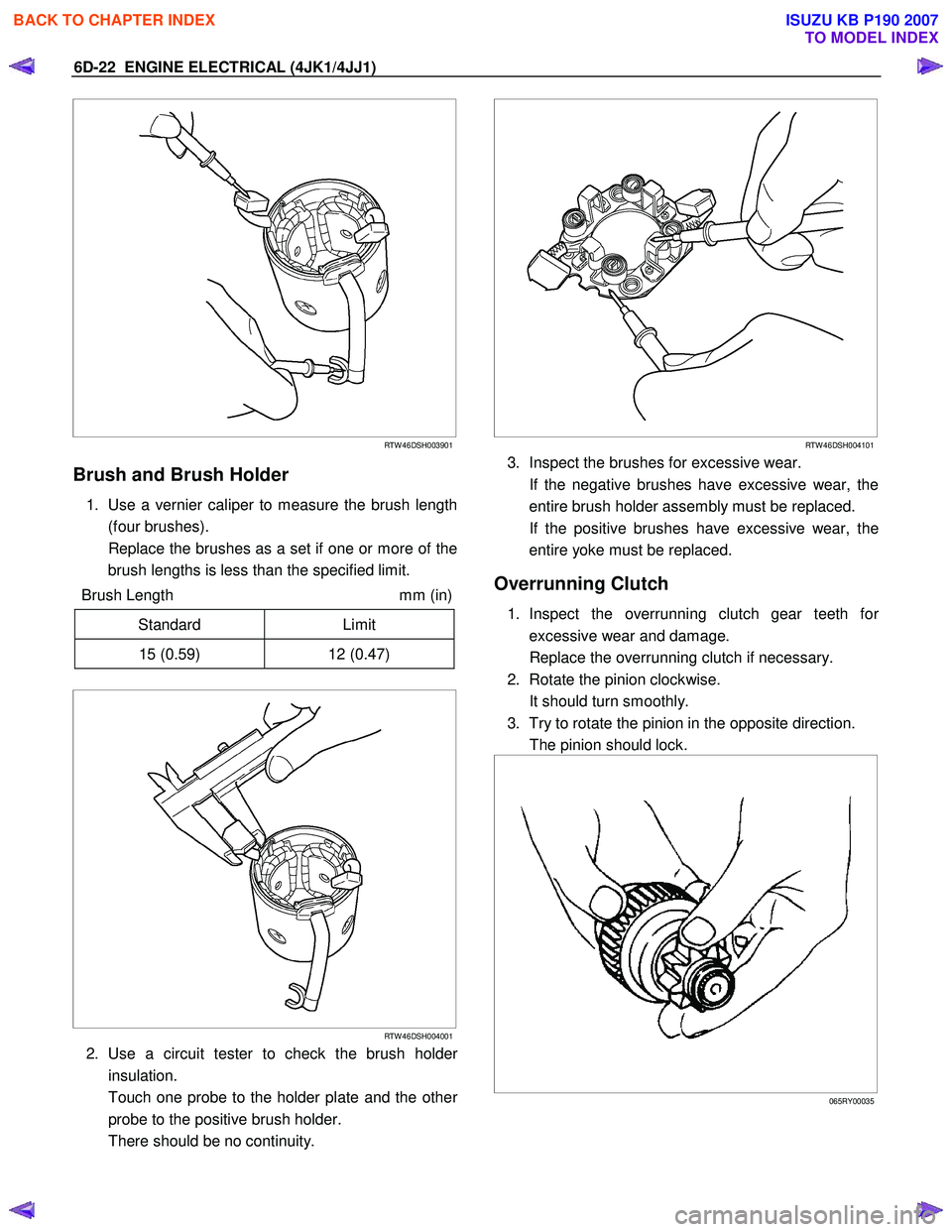
Brush and Brush Holder
1. Use a vernier caliper to measure the brush length
(four brushes).
Replace the brushes as a set if one or more of the brush lengths is less than the specified limit.
Brush Length mm (in)
Standard Limit
15 (0.59) 12 (0.47)
RTW 46DSH004001
2. Use a circuit tester to check the brush holder
insulation.
Touch one probe to the holder plate and the othe
r
probe to the positive brush holder.
There should be no continuity.
RTW 46DSH004101
3. Inspect the brushes for excessive wear.
If the negative brushes have excessive wear, the entire brush holder assembly must be replaced.
If the positive brushes have excessive wear, the entire yoke must be replaced.
Overrunning Clutch
1. Inspect the overrunning clutch gear teeth for
excessive wear and damage.
Replace the overrunning clutch if necessary.
2. Rotate the pinion clockwise.
It should turn smoothly.
3. Try to rotate the pinion in the opposite direction.
The pinion should lock.
065RY00035
BACK TO CHAPTER INDEX
TO MODEL INDEX
ISUZU KB P190 2007
Page 2037 of 6020
ENGINE MECHANICAL (C24SE) 6A-23
Toothed Belt Tension, Adjust
(Engines with toothed belt tension
roller)
Removal
Refer to 6A-21. Toothed Belt and Timing check and removal
steps.
Adjust
1. Loosen the fastening bolt of the toothed belt tension roller.
2. Turn the toothed belt tension roller at adjustment eccentric (1) in the direction of arrow (counterclockwise),
until pointer (2) comes to the right stop.
3. If necessary tighten the fastening bolt of toothed belt tension roller.
4. Rotate the crankshaft twice (720
°) in the engine
rotational direction until marks (2) and (1) align again.
5. Turn the eccentric in the direction of arrow (clockwise)
until pointer (1) and notch (2) are positioned to suit age of
toothed belt.
6. Rotate the crankshaft twice (720 °) in the engine
rotational direction again and correct adjustment if
necessary.
Installation
Refer to 6A-21. Toothed Belt and Timing check and installation
steps.
BACK TO CHAPTER INDEX
TO MODEL INDEX
ISUZU KB P190 2007
Page 2039 of 6020
ENGINE MECHANICAL (C24SE) 6A-25
Adjust
Loosen the fastening bolt of the toothed belt tension roller and
turn the adjustment eccentric in the direction of arrow
(clockwise) until pointer (1) comes to the left stop.
Remove the toothed belt.
Installation
1. Install a new toothed belt while keeping tension side taut.
Adjust
Toothed belt tension - see operation " Toothed Belt Tension".
2. Install the toothed belt to the cover.
3. Install the crankshaft pulley while counterholding on the fastening bolt of toothed belt drive gear.
4. Install the fan shroud.
5. Install the fan belt.
6. Install the V-belt for A/C.
7. Install the V-belt for power steering.
8. Install the fan.
9. Install the belts to the bracket for alternator.
BACK TO CHAPTER INDEX
TO MODEL INDEX
ISUZU KB P190 2007
Page 2158 of 6020

6D3-10 STARTING AND CHARGING SYSTEM
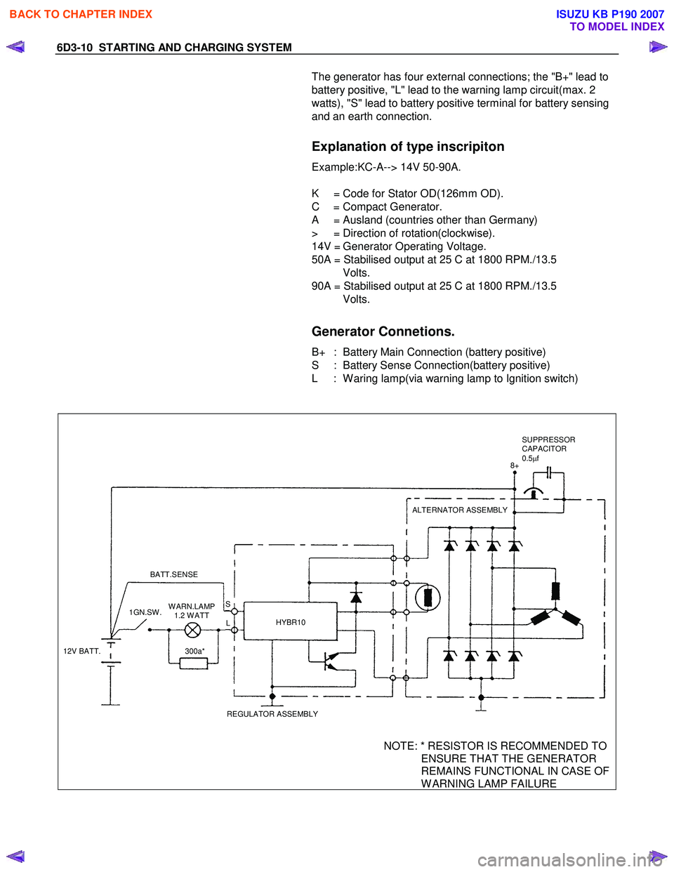
The generator has four external connections; the "B+" lead to
battery positive, "L" lead to the warning lamp circuit(max. 2
watts), "S" lead to battery positive terminal for battery sensing
and an earth connection.
Explanation of type inscripiton
Example:KC-A--> 14V 50-90A.
K = Code for Stator OD(126mm OD).
C = Compact Generator.
A = Ausland (countries other than Germany)
> = Direction of rotation(clockwise).
14V = Generator Operating Voltage.
50A = Stabilised output at 25 C at 1800 RPM./13.5
Volts.
90A = Stabilised output at 25 C at 1800 RPM./13.5
Volts.
Generator Connetions.
B+ : Battery Main Connection (battery positive)
S : Battery Sense Connection(battery positive)
L : W aring lamp(via warning lamp to Ignition switch)
BATT.SENSE
REGULATOR ASSEMBLYHYBR10 ALTERNATOR ASSEMBLY
12V BATT. 1GN.SW .
300a*
W ARN.LAMP
1.2 W ATT L
S 8+
SUPPRESSOR
CAPACITOR
0.5 µf
NOTE: * RESISTOR IS RECOMMENDED TO
ENSURE THAT THE GENERATOR
REMAINS FUNCTIONAL IN CASE OF
W ARNING LAMP FAILURE
BACK TO CHAPTER INDEX
TO MODEL INDEX
ISUZU KB P190 2007
Page 2538 of 6020

Engine Mechanical – V6 Page 6A1–59
3.5 Accessory Drive Belt
RWD Vehicle
Remove
1 Remove the air intake duct from between the air flow meter and the throttle body, refer to 6C1-3 Engine
Management – V6 – Service Operations.
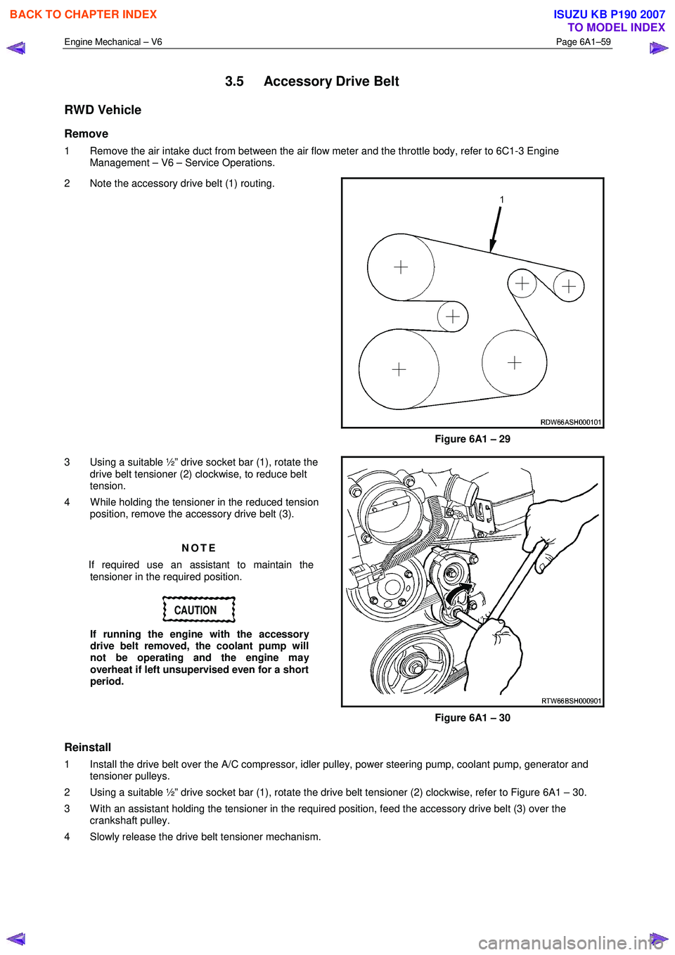
2 Note the accessory drive belt (1) routing.
Figure 6A1 – 29
3 Using a suitable ½” drive socket bar (1), rotate the drive belt tensioner (2) clockwise, to reduce belt
tension.
4 W hile holding the tensioner in the reduced tension position, remove the accessory drive belt (3).
NOTE
If required use an assistant to maintain the tensioner in the required position.
CAUTION
If running the engine with the accessory
drive belt removed, the coolant pump will
not be operating and the engine may
overheat if left unsupervised even for a short
period.
Figure 6A1 – 30
Reinstall
1 Install the drive belt over the A/C compressor, idler pulley, power steering pump, coolant pump, generator and tensioner pulleys.
2 Using a suitable ½” drive socket bar (1), rotate the drive belt tensioner (2) clockwise, refer to Figure 6A1 – 30.
3 W ith an assistant holding the tensioner in the required position, feed the accessory drive belt (3) over the crankshaft pulley.
4 Slowly release the drive belt tensioner mechanism.
BACK TO CHAPTER INDEX
TO MODEL INDEX
ISUZU KB P190 2007
Page 2575 of 6020
Engine Mechanical – V6 Page 6A1–96
Remove
Right-hand Secondary Timing Chain
CAUTION
After removing the upper intake manifold, and
spark plugs, plug any openings to prevent dirt
and other contaminants from entering.
1 Remove the engine front cover assembly, refer to 3.15 Front Cover Assembly.
2 Remove the spark plugs to aid crankshaft/engine rotation, refer to 6C1-3 Engine Management – V6 – Service Operations.
3 Install Tool No. EN46111 (1) onto the crankshaft (2).
Figure 6A1 – 101
4 Using Tool No. EN46111 (1), rotate the crankshaft in a clockwise direction until the crankshaft sprocket
timing mark (2) is aligned with the indexing mark (3)
on the oil pump housing.
Figure 6A1 – 102
BACK TO CHAPTER INDEX
TO MODEL INDEX
ISUZU KB P190 2007
Page 2587 of 6020
Engine Mechanical – V6 Page 6A1–108
Primary Timing Chain Tensioner
Figure 6A1 – 133
1 Inspect the primary timing chain tensioner for worn shoe surface (1), refer to Figure 6A1 – 133.
2 Inspect the tensioner for a locked or binding tensioner shaft (2). Reset the plunger (3) and ensure the tensioner shaft moves freely in and out of the body of the tensioner.
NOTE
To reset the tensioner, use a suitably sized flat
blade screwdriver or Tool No. J 45027 (4) to wind
the plunger in a clockwise direction, into the
tensioner shaft.
3 Replace a damaged tensioner as required.
Left-hand Secondary Timing Chain Guide
1 Inspect the left-hand secondary timing chain guide for the following:
• worn guide surface (1),
• cracked or broken guide surface (2), and
• cracked or damaged guide base (3).
2 Replace a damaged guide as required.
Figure 6A1 – 134
BACK TO CHAPTER INDEX
TO MODEL INDEX
ISUZU KB P190 2007