Page 829 of 6020

6A – 24 ENGINE MECHANICAL
SERVICING
Servicing refers to general maintenance procedures to be performed by qualified service personnel.
RTW 36ASH000401
MODEL IDENTIFICATION
Engine Serial Number
The engine number is stamped on the rear left hand side
of the cylinder body.
The engine number is stamped in the plate in front of the
engine room as well.
AIR CLEANER
Element cleaning procedures will vary according to the
condition of the element.
Dust Fouled Element (Except wet type element)
Rotate the element with your hand while applying
compressed air to the inside of the element. This will blow
the dust free.
Compressed air pressure kPa (kg/cm
2 /psi)
392 – 490 (4 – 5/57 – 71)
LUBRICATING SYSTEM
Main Oil Filter (Cartridge Type Paper Element)
Replacement Procedure
1. Drain the engine oil.
2. Retighten the drain plug.
3. Loosen the used oil filter by turning it counterclockwise with a filter wrench.
Filter W rench: 5-8840-0200-0
RTW 36ASH000101
4. Clean the oil cooler fitting face. This will allow the new oil filter to seat properly.
5. Apply a light coat of engine oil to the filter O-ring.
6. Turn in the new oil filter until the filter O-ring is fitted against the sealing face.
7. Use the filter wrench to turn in the filter an additional 2/3 turns.
Filter W rench: 5-8840-0200-0
8. Check the engine oil level and replenish to the specified level if required.
130RY00003
6A-6
BACK TO CHAPTER INDEX
TO MODEL INDEX
ISUZU KB P190 2007
Page 830 of 6020

ENGINE MECHANICAL 6A – 25
Replenished Engine Oil MAX lit (US/UK gal)
Condition
Model Engine Dry
W ith oil filter
replacement W ithout oil
filter
replacement
4 × 2
4 × 4
(4JA1L/TC)6.2 (1.64/1.36) 5.2 ∼ 4.2
(1.37 ∼ 1.11
/ 1.14 ∼ 0.92) 4.5
∼ 3.5
(1.19 ∼ 0.93
/ 0.99 ∼ 0.77)
4 × 2
(4JH1TC)
6.2 (1.64/1.36) 5.2
∼ 4.2
(1.37 ∼ 1.11
/ 1.14 ∼ 0.92) 4.5
∼ 3.5
(1.19 ∼ 0.93
/ 0.99 ∼ 0.77)
4 × 4
(4JH1TC) 7.0 (1.85/1.54) 6.2 ∼ 5.2
(1.64 ∼ 1.37
/ 1.36 ∼ 1.14) 5.3
∼ 4.3
(1.72 ∼ 1.14
/ 1.17 ∼ 0.95)
9. Start the engine and check for oil leakage from the
main oil filter.
RTW 66ASH003201
FUEL SYSTEM
Fuel Filter Replacement Procedure
1. Remove the fuel filter by turning it counterclockwise with a filter wrench.
Filter W rench: 5-8840-0253-0 (J-22700)
Note:
Be careful not to spill the fuel in the filter cartridge.
RTW 66ASH003301
2. Clean the fuel filter cartridge fitting faces. This will allow the new fuel filter to seat properly
3. Apply a light coat of engine oil to the O-ring.
4. Turn in the fuel filter until the sealing face comes in contact with the O-ring.
5. Turn in the fuel filter an additional 2/3 of a turn with a filter wrench.
Filter W rench : 5-8840-0253-0 (J-22700)
6. Operate the priming pump until the air discharged completely from fuel system.
7. Start the engine and check for fuel leakage.
Note:
The use of an ISUZU genuine fuel filter is strongly
recommended.
041RY00009
BACK TO CHAPTER INDEX
TO MODEL INDEX
ISUZU KB P190 2007
Page 839 of 6020

6A – 34 ENGINE MECHANICAL
RTW 46ASH000701
9. Turn the crankshaft clockwise and read the gauge
indication when the crankshaft pulley timing mark (8 °)
is aligned with the pointer.
Injection Timing : BTDC 8 ° ± 2 °
Standard Reading mm (in)
0.5 (0.02)
If the injection timing is outside the specified range,
continue with the following steps.
10. Loosen the injection pump fixing nuts and bracket bolts.
11. Adjust the injection pump setting angle.
W hen large than standard value W hen smaller than standard
value
R A
A: Move the injection pump toward the engine.
R: Move the injection pump away from the engine.
12. Install the distributor head bolt.
Distributor head bolt torque N·m (kg·m /lb·ft)
29 (3.0/22)
ENGINE CONTROL (4JA1T(L) only)
Idling Speed Adjustment
1. Set the vehicle parking brake and chock the drive wheels.
2. Place the transmission in neutral.
3. Start the engine and allow it to idle until the coolant temperature reaches 70 - 80 °C (158 - 176 °F).
4. Disconnect the engine control cable from the control lever.
5. Set a tachometer to the engine.
6. Check the engine idling speed. If the engine idling speed is outside the specified
range, it must be adjusted.
Engine Idling Speed : 730 ± 25 rpm
BACK TO CHAPTER INDEX
TO MODEL INDEX
ISUZU KB P190 2007
Page 915 of 6020

6A – 110 ENGINE MECHANICAL
17. Cylinder Body Rear Plate
1. Align the rear plate with the cylinder body knock pins.
2. Tighten the rear plate to the specified torque.
Rear Plate Torque N·m(kg·m/lbft)
82 (8.4/61)
18. Flywheel
1. Apply a coat of engine oil to the threads of the flywheel bolts.
2. Align the flywheel with the crankshaft dowel pin.
3. Tighten the flywheel bolts in the numerical order shown in the illustration.
Gear stoper: 5-8840-0214-0
Flywheel Bolt Torque N·m(kg·m/lbft)
118 (12/87)
19. Crankshaft Timing Gear
Use the crankshaft timing gear installer (1) to install the
crankshaft timing gear (2).
The crankshaft timing gear setting mark must be facing
outward.
Crankshaft Timing Gear Installer: 9-8522-0020-0
20. Idler Gear Shaft
21. Idler Gear "A"
1. Turn the crankshaft clockwise to set the DTC of the No.1 piston.
2. Apply engine oil to the idler gear and the idler gear shaft.
The idler gear shaft oil hole (A) must be facing up.
3. Position the idler gear setting marks so that they are facing the front of the engine.
015LX113
020R100001
020RY00034
020RY00035
BACK TO CHAPTER INDEX
TO MODEL INDEX
ISUZU KB P190 2007
Page 1003 of 6020
6D – 2 ENGINE ELECTRICAL
MAIN DATA AND SPECIFICATIONS
Description
Item
60A 80A
Generator
Type
AC generator with IC regulator and vacuum pump
Hitachi LR160-503E Hitachi LR180-513B
Voltage V
Drive and rotation
Ground polarity 12
V-belt, clockwise viewed from the drive pulley Negative
Maximum output A 60 80
Engine speed ratio to 1 1.788
Maximum speed rpm 11,000
Weight with vacuum pump kg(lb) 5.8(12.8) 6.4(14.1)
Vacuum Pump
Delivery volume cm3/rev
Exhaust Characteristic
Maximum vacuum
50
-66.7 kPa (-500 mmHg) bulid up time 21 seconds or less at 1,000 rpm
7 seconds or less at 5,000 rpm
-90.7 kPa (-680 mmHg) or more
Starter Motor
Type
Solenoid controlled
Hitachi S13-555
12
2.3
8.76 300 Rated voltage V
Rated output kW
Load characteristics
Terminal voltage V
Load current A
Weight kg(Ib) 4.7 (10.4)
BACK TO CHAPTER INDEX
TO MODEL INDEX
ISUZU KB P190 2007
Page 1029 of 6020

6D – 28 ENGINE ELECTRICAL
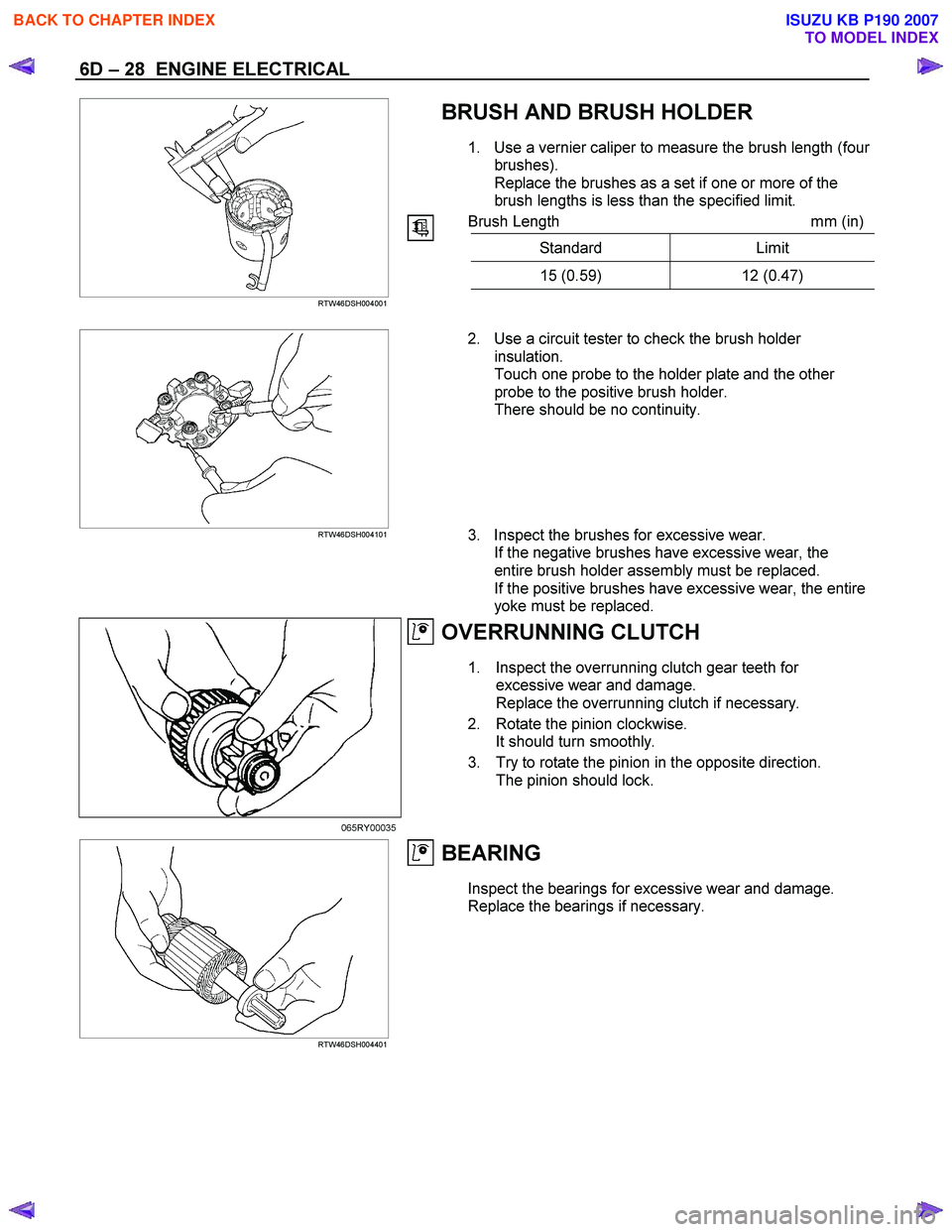
BRUSH AND BRUSH HOLDER
1. Use a vernier caliper to measure the brush length (four
brushes).
Replace the brushes as a set if one or more of the
brush lengths is less than the specified limit.
Brush Length mm (in)
Standard Limit
15 (0.59) 12 (0.47)
RTW46DSH004001
RTW46DSH004101
2. Use a circuit tester to check the brush holder
insulation.
Touch one probe to the holder plate and the other
probe to the positive brush holder.
There should be no continuity.
3. Inspect the brushes for excessive wear. If the negative brushes have excessive wear, the
entire brush holder assembly must be replaced.
If the positive brushes have excessive wear, the entire
yoke must be replaced.
OVERRUNNING CLUTCH
1. Inspect the overrunning clutch gear teeth for excessive wear and damage.
Replace the overrunning clutch if necessary.
2. Rotate the pinion clockwise. It should turn smoothly.
3. Try to rotate the pinion in the opposite direction. The pinion should lock.
065RY00035
RTW46DSH004401
BEARING
Inspect the bearings for excessive wear and damage.
Replace the bearings if necessary.
BACK TO CHAPTER INDEX
TO MODEL INDEX
ISUZU KB P190 2007
Page 1507 of 6020
ENGINE MECHANICAL (4JK1/4JJ1) 6A-147
Reassembly
1. Install the gasket on the element.
2. Install the element.
3. Tighten the element fixing nut using the specified torque.
Tightening torque: 25 N ⋅
⋅⋅
⋅
m (2.5 kg ⋅
⋅⋅
⋅
m / 18 lb ft)
Installation
1. Install the oil filter and cooler.
• Install the O-ring on the oil filter and cooler,
apply grease.
•
Apply the liquid gasket and mount within 5
minutes. Apply liquid gasket (ThreeBond TB-
1207C or equivalent) to the flange surface
groove (cylinder block). Bead diameter must
be between 2 and 3 mm (0.079 and 0.118 in).
Refer to the illustration for the offset position
(no more than 1 mm (0.004 in)).
RTW 56ASH013101
Legend
1. Liquid Gasket
2. O-ring
• Align the oil filter and cooler holes with the
cylinder block studs. Install the oil cooler to the
cylinder clock.
BACK TO CHAPTER INDEX
TO MODEL INDEX
ISUZU KB P190 2007
Page 1554 of 6020

FUEL SYSTEM (4JK1/4JJ1) 6C-13
Fuel Filter Element
Removal
1. Detach the drain hose on the lower part of the fuel
filter or the drain plug, loosen the air bleed plug,
and drain the fuel from the fuel filter.
2. Detach the water-in-fuel switch harness.
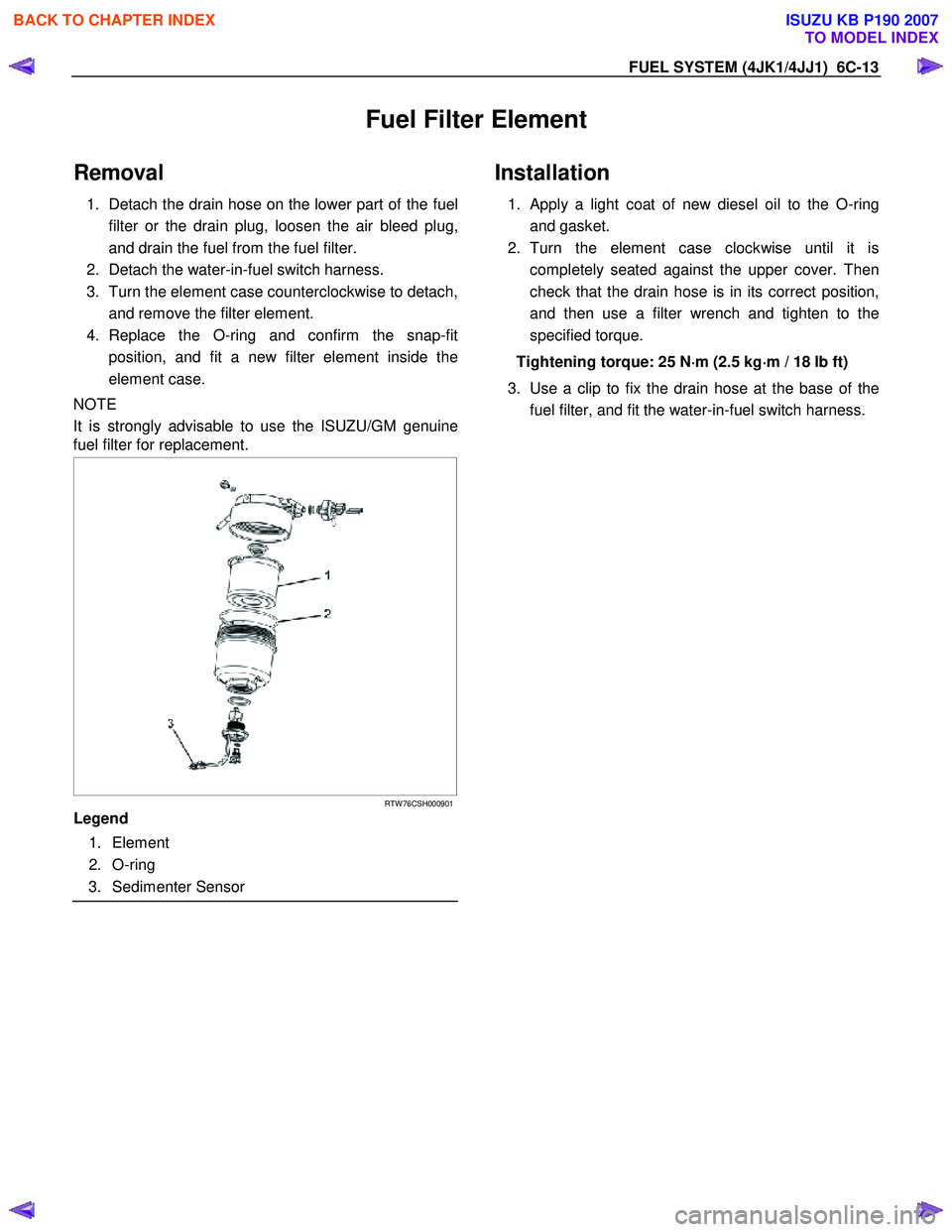
3. Turn the element case counterclockwise to detach, and remove the filter element.
4. Replace the O-ring and confirm the snap-fit position, and fit a new filter element inside the
element case.
NOTE
It is strongly advisable to use the ISUZU/GM genuine
fuel filter for replacement.
RTW 76CSH000901
Legend
1. Element
2. O-ring
3. Sedimenter Sensor
Installation
1. Apply a light coat of new diesel oil to the O-ring
and gasket.
2. Turn the element case clockwise until it is completely seated against the upper cover. Then
check that the drain hose is in its correct position,
and then use a filter wrench and tighten to the
specified torque.
Tightening torque: 25 N ⋅
⋅⋅
⋅
m (2.5 kg ⋅
⋅⋅
⋅
m / 18 lb ft)
3. Use a clip to fix the drain hose at the base of the fuel filter, and fit the water-in-fuel switch harness.
BACK TO CHAPTER INDEX
TO MODEL INDEX
ISUZU KB P190 2007