Page 3566 of 6020
Engine Management – V6 – Service Operations Page 6C1-3–42
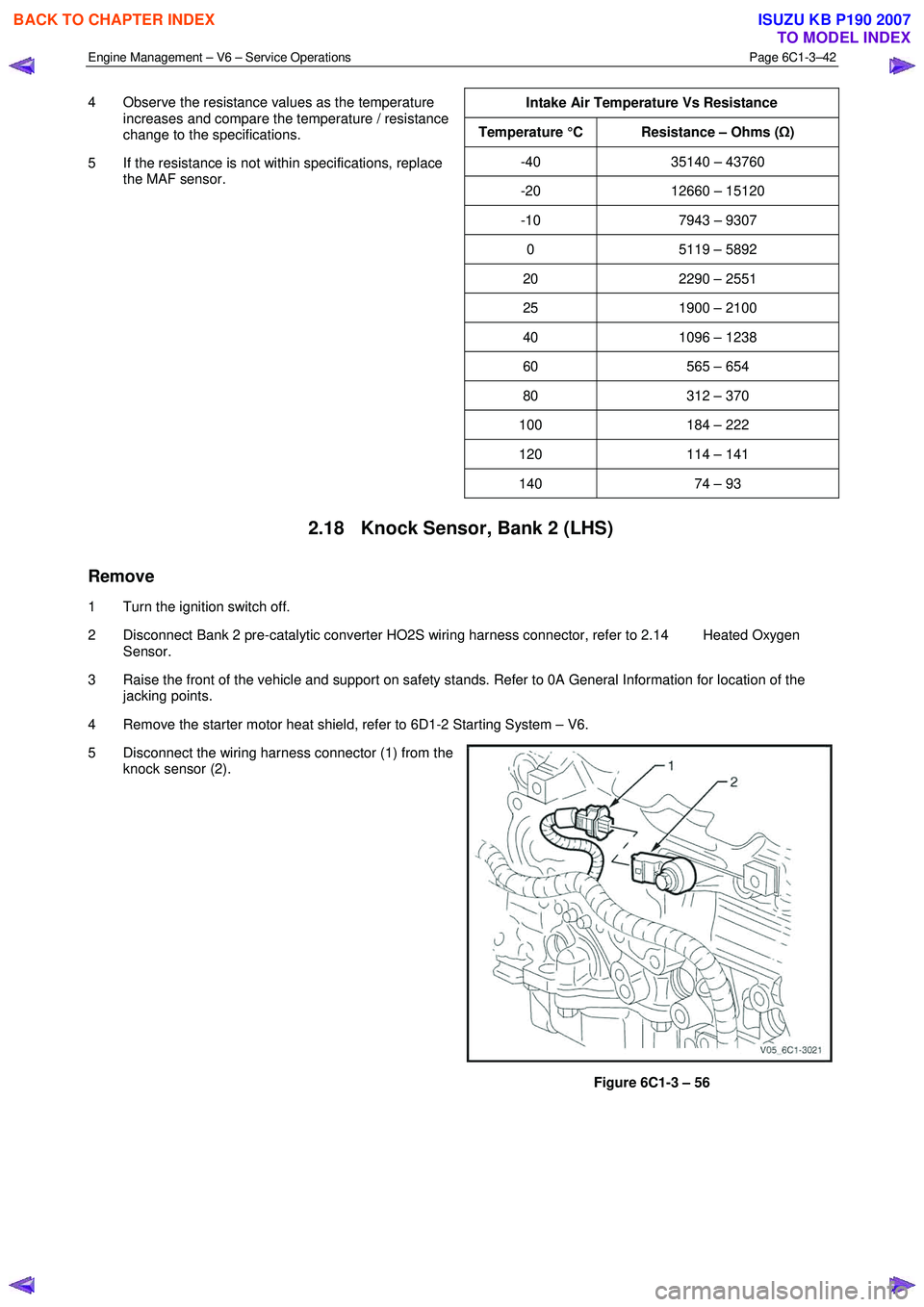
4 Observe the resistance values as the temperature
increases and compare the temperature / resistance
change to the specifications.
5 If the resistance is not within specifications, replace the MAF sensor.
Intake Air Temperature Vs Resistance
Temperature °C Resistance – Ohms (
Ω)
-40 35140 – 43760
-20 12660 – 15120
-10 7943 – 9307
0 5119 – 5892
20 2290 – 2551
25 1900 – 2100
40 1096 – 1238
60 565 – 654
80 312 – 370
100 184 – 222
120 114 – 141
140 74 – 93
2.18 Knock Sensor, Bank 2 (LHS)
Remove
1 Turn the ignition switch off.
2 Disconnect Bank 2 pre-catalytic converter HO2S wiring harness connector, refer to 2.14 Heated Oxygen Sensor.
3 Raise the front of the vehicle and support on safety stands. Refer to 0A General Information for location of the jacking points.
4 Remove the starter motor heat shield, refer to 6D1-2 Starting System – V6.
5 Disconnect the wiring harness connector (1) from the knock sensor (2).
Figure 6C1-3 – 56
BACK TO CHAPTER INDEX
TO MODEL INDEX
ISUZU KB P190 2007
Page 3568 of 6020
Engine Management – V6 – Service Operations Page 6C1-3–44
3 Disconnect the wiring harness connector (1) from the
knock sensor (2).
Figure 6C1-3 – 59
4 Remove the bolt (1) attaching the knock sensor (2) to the engine block, and remove the knock sensor.
Figure 6C1-3 – 60
Reinstall
Reinstallation of the knock sensor is the reverse of the removal procedure, noting the following:
1 Ensure the knock sensor mounting surface is flat and free of any dirt, oxidisation, etc.
BACK TO CHAPTER INDEX
TO MODEL INDEX
ISUZU KB P190 2007
Page 3570 of 6020
Engine Management – V6 – Service Operations Page 6C1-3–46
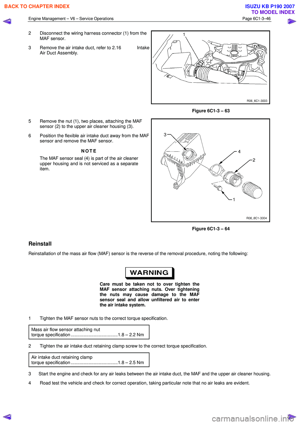
2 Disconnect the wiring harness connector (1) from the
MAF sensor.
3 Remove the air intake duct, refer to 2.16 Intake Air Duct Assembly.
Figure 6C1-3 – 63
5 Remove the nut (1), two places, attaching the MAF sensor (2) to the upper air cleaner housing (3).
6 Position the flexible air intake duct away from the MAF sensor and remove the MAF sensor.
NOTE
The MAF sensor seal (4) is part of the air cleaner
upper housing and is not serviced as a separate
item.
Figure 6C1-3 – 64
Reinstall
Reinstallation of the mass air flow (MAF) sensor is the reverse of the removal procedure, noting the following:
Care must be taken not to over tighten the
MAF sensor attaching nuts. Over tightening
the nuts may cause damage to the MAF
sensor seal and allow unfiltered air to enter
the air intake system.
1 Tighten the MAF sensor nuts to the correct torque specification. Mass air flow sensor attaching nut
torque specification .....................................1.8 – 2.2 Nm
2 Tighten the air intake duct retaining clamp screw to the correct torque specification. Air intake duct retaining clamp
torque specification .....................................1.8 – 2.5 Nm
3 Start the engine and check for any air leaks between the air intake duct, the MAF and the upper air cleaner housing.
4 Road test the vehicle and check for correct operation, taking particular note that no air leaks are evident.
BACK TO CHAPTER INDEX
TO MODEL INDEX
ISUZU KB P190 2007
Page 3578 of 6020

Engine Management – V6 – Service Operations Page 6C1-3–54
2 Loosen the air intake duct to throttle body assembly
retaining clamp (1).
3 Pull the air intake duct (2) away from the throttle body assembly.
NOTE
If difficulty is experienced in removing the air
intake duct from the throttle body, completely
remove the air intake duct assembly, refer to
2.16 Intake Air Duct Assembly.
Figure 6C1-3 – 71
4 Unclip the wiring harness from the retaining clip (1).
Do not use any mechanical device such as a
screwdriver to disengage the harness
connector (2) from the throttle body.
5 Disconnect the wiring harness connector by: NOTE
When sliding the connector lock, take care not to
disengage it from the connector.
• Sliding the connector lock (3) in the direction of
the arrow, then
• press the connector latch in the direction of the
arrow (4), and remove the connector from the
throttle body.
Figure 6C1-3 – 72
6 Remove the four bolts (1), attaching the throttle body (2) to the upper intake manifold (3).
7 Remove the throttle body and gasket (4).
Figure 6C1-3 – 73
BACK TO CHAPTER INDEX
TO MODEL INDEX
ISUZU KB P190 2007
Page 3579 of 6020
Engine Management – V6 – Service Operations Page 6C1-3–55
Inspect
The following throttle body inspection procedure may be carried out with the throttle body installed on the vehicle. Prior to
performing a throttle body on-vehicle inspection:
• Turn the ignition switch off.
• Disconnect the throttle body wiring harness connector. Refer to Remove in this Section.
• Remove the air intake duct, refer to 2.16 Intake Air Duct Assembly.
To avoid serious personal injury, never
attempt to rotate the throttle plate manually
whilst the throttle body harness connector is
connected to the throttle body.
1 Fully open the throttle plate by hand and inspect the throttle body bore and throttle plate for any deposits.
When cleaning / inspecting the throttle body:
• Do not subject the throttle body assembly
to an immersion cleaner or a strong
solvent. Damage to the throttle position
sensor and / or sealed throttle shaft
bearings will result.
• Never use a wire brush or scraper to clean
the throttle body. A wire brush or sharp
tool may damage the throttle body
components.
2 Use a clean shop towel and a spray type hydro-carbon cleaner to clean the throttle body bore and throttle plate. If necessary, use a parts cleaning brush to remove heavy deposits.
3 Inspect the throttle body for a binding throttle plate by fully opening and closing the throttle plate by hand. It should open and close smoothly.
4 Inspect the throttle body for a bent or damaged throttle plate, cracks, corrosion, or distortion in the throttle body housing.
NOTE
The throttle body contains no serviceable parts
and should not be disassembled. If the throttle
body is damaged it must be replaced as an
assembly.
5 If the throttle body is affected by any of the above conditions, it must be replaced.
6 If an on-vehicle throttle body inspection was performed, perform the following:
• Reinstall the air intake duct, refer to 2.16 Intake Air Duct Assembly.
• Reconnect the throttle body wiring harness connector, refer to Reinstall in this Section.
• Road test the vehicle and check for correct operation, taking particular note that no air leaks are evident.
Reinstall
Reinstallation of the throttle body assembly is the reverse of the removal procedure, noting the following:
1 Ensure the throttle body and upper intake manifold mating surfaces are clean and free of foreign material.
2 Install a new throttle body to upper intake manifold gasket.
BACK TO CHAPTER INDEX
TO MODEL INDEX
ISUZU KB P190 2007
Page 3580 of 6020
Engine Management – V6 – Service Operations Page 6C1-3–56
3 Reinstall the throttle body bolts and tighten to the correct torque specification.
Throttle body assembly attaching bolt
torque specification ...................................8.0 – 12.0 Nm
After reinstalling the wiring harness
connector, ensure the connector latch (1) and
connector lock (2) have fully engaged.
4 Reinstall the wiring harness connector to the throttle body, ensuring the connector latch and connector slide
have fully engaged.
5 Ensure the wiring harness is correctly routed and attached securely in the throttle body harness
retaining clip (3).
Figure 6C1-3 – 74
6 Road test the vehicle and check for correct operation, taking particular note that no air leaks are evident.
BACK TO CHAPTER INDEX
TO MODEL INDEX
ISUZU KB P190 2007
Page 3596 of 6020
Charging System – V6 Page 6D1-1-9
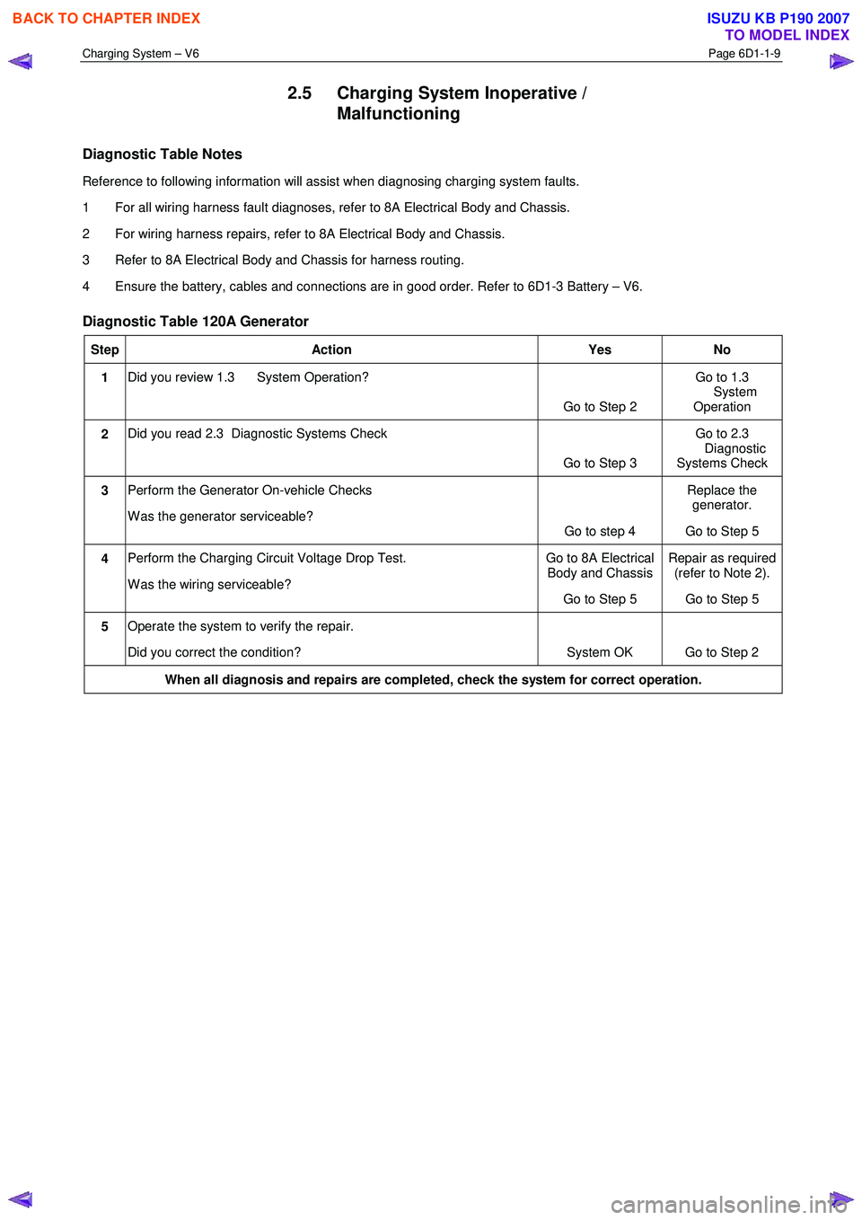
2.5 Charging System Inoperative /
Malfunctioning
Diagnostic Table Notes
Reference to following information will assist when diagnosing charging system faults.
1 For all wiring harness fault diagnoses, refer to 8A Electrical Body and Chassis.
2 For wiring harness repairs, refer to 8A Electrical Body and Chassis.
3 Refer to 8A Electrical Body and Chassis for harness routing.
4 Ensure the battery, cables and connections are in good order. Refer to 6D1-3 Battery – V6.
Diagnostic Table 120A Generator
Step Action Yes No
1 Did you review 1.3 System Operation?
Go to Step 2 Go to 1.3
System Operation
2 Did you read 2.3 Diagnostic Systems Check
Go to Step 3 Go to 2.3
Diagnostic
Systems Check
3 Perform the Generator On-vehicle Checks
W as the generator serviceable? Go to step 4 Replace the
generator.
Go to Step 5
4 Perform the Charging Circuit Voltage Drop Test.
W as the wiring serviceable? Go to 8A Electrical
Body and Chassis
Go to Step 5 Repair as required
(refer to Note 2).
Go to Step 5
5 Operate the system to verify the repair.
Did you correct the condition? System OK Go to Step 2
When all diagnosis and repairs are completed, check the system for correct operation.
BACK TO CHAPTER INDEX
TO MODEL INDEX
ISUZU KB P190 2007
Page 3598 of 6020
Charging System – V6 Page 6D1-1-11
3.3 On-vehicle Testing
Generator On-vehicle Checks
Prerequisites
Before testing the generator output, ensure that:
• all generator circuit connections are clean and tight,
• the generator is always connected to the battery during testing (to prevent damage to the diodes),
• the battery is fully charged, and
• the specific gravity does not vary more than 0.025 between cells. (It is recommended the average specific gravity
is 1.260 or higher). Refer to 6D1-3 Battery – V6.
Carry out a load test on the battery to determine its ability to supply and accept current. This is a good indicator of the
general condition of the battery. For details of battery testing, refer to 6D1-3 Battery – V6.
Inspect the drive belt and tensioner markings to determine if the drive belt is within operating limits. Replace the belt if it
is excessively worn or outside the operating range of the tensioner.
For further details, refer to 6A1 Engine Mechanical – V6.
Generator Test
Regulating Voltage Test
NOTE
Leave the generator E-4 wiring harness
connector connected, as it provides initial field
excitation.
1 Ensure the ignition switch is in the OFF position and all electrical equipment is turned off.
Refer to 1.2 WARNING, CAUTION and
NOTES before disconnecting the battery.
2 Disconnect the battery ground cable P-5 at the battery.
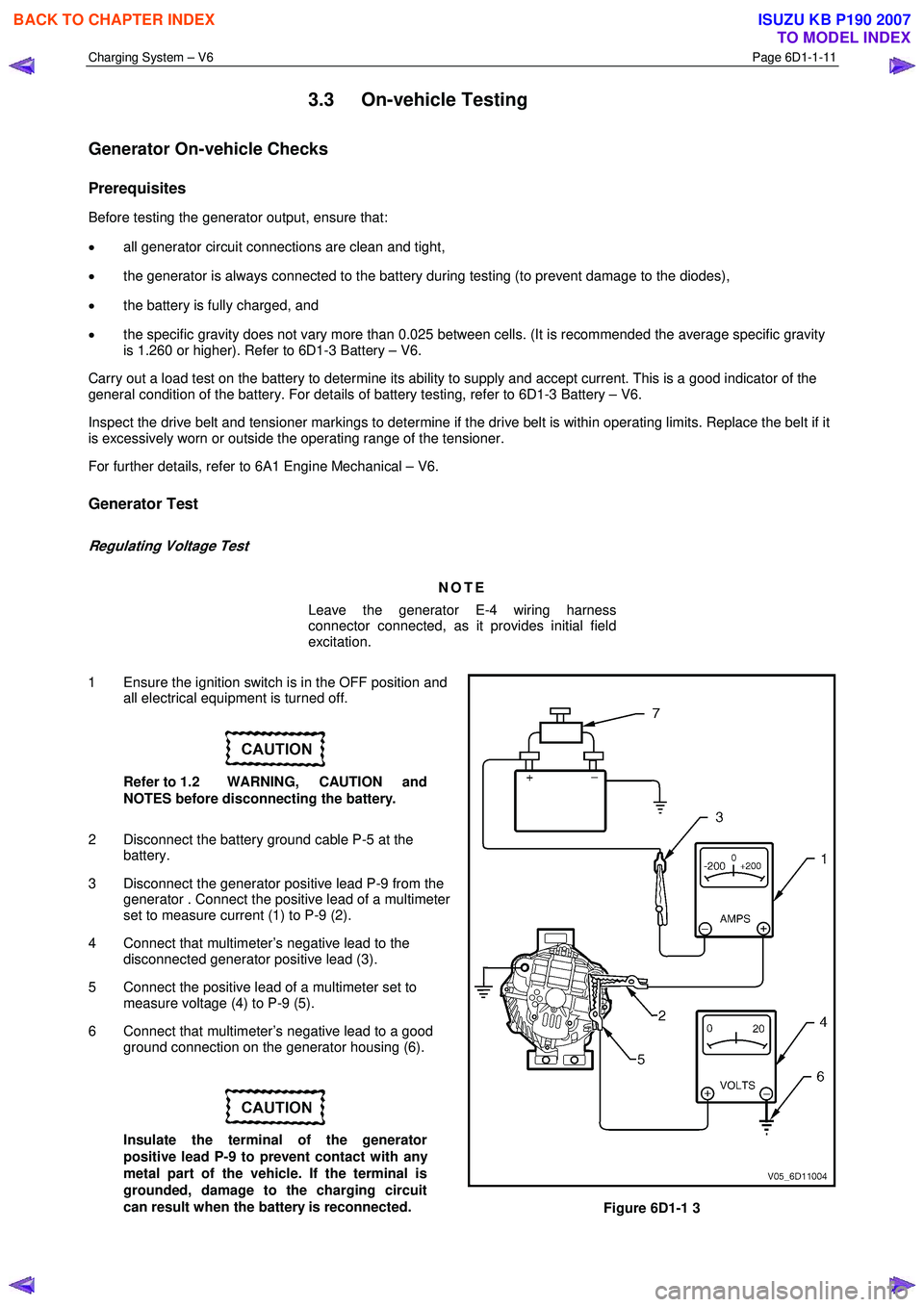
3 Disconnect the generator positive lead P-9 from the generator . Connect the positive lead of a multimeter
set to measure current (1) to P-9 (2).
4 Connect that multimeter’s negative lead to the disconnected generator positive lead (3).
5 Connect the positive lead of a multimeter set to measure voltage (4) to P-9 (5).
6 Connect that multimeter’s negative lead to a good ground connection on the generator housing (6).
Insulate the terminal of the generator
positive lead P-9 to prevent contact with any
metal part of the vehicle. If the terminal is
grounded, damage to the charging circuit
can result when the battery is reconnected.
Figure 6D1-1 3
BACK TO CHAPTER INDEX
TO MODEL INDEX
ISUZU KB P190 2007