2007 ISUZU KB P190 Harness
[x] Cancel search: HarnessPage 3450 of 6020
Engine Management – V6 – Diagnostics Page 6C1-2–172
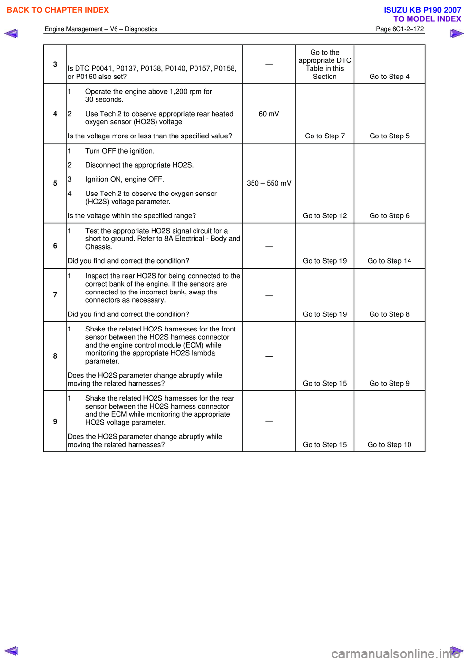
3
Is DTC P0041, P0137, P0138, P0140, P0157, P0158,
or P0160 also set? —
Go to the
appropriate DTC Table in this Section Go to Step 4
4 1 Operate the engine above 1,200 rpm for
30 seconds.
2 Use Tech 2 to observe appropriate rear heated oxygen sensor (HO2S) voltage
Is the voltage more or less than the specified value? 60 mV
Go to Step 7 Go to Step 5
5 1 Turn OFF the ignition.
2 Disconnect the appropriate HO2S.
3 Ignition ON, engine OFF.
4 Use Tech 2 to observe the oxygen sensor (HO2S) voltage parameter.
Is the voltage within the specified range? 350 – 550 mV
Go to Step 12 Go to Step 6
6 1 Test the appropriate HO2S signal circuit for a
short to ground. Refer to 8A Electrical - Body and
Chassis.
Did you find and correct the condition? —
Go to Step 19 Go to Step 14
7 1 Inspect the rear HO2S for being connected to the
correct bank of the engine. If the sensors are
connected to the incorrect bank, swap the
connectors as necessary.
Did you find and correct the condition? —
Go to Step 19 Go to Step 8
8 1 Shake the related HO2S harnesses for the front
sensor between the HO2S harness connector
and the engine control module (ECM) while
monitoring the appropriate HO2S lambda
parameter.
Does the HO2S parameter change abruptly while
moving the related harnesses? —
Go to Step 15 Go to Step 9
9 1 Shake the related HO2S harnesses for the rear
sensor between the HO2S harness connector
and the ECM while monitoring the appropriate
HO2S voltage parameter.
Does the HO2S parameter change abruptly while
moving the related harnesses? —
Go to Step 15 Go to Step 10
BACK TO CHAPTER INDEX
TO MODEL INDEX
ISUZU KB P190 2007
Page 3451 of 6020
Engine Management – V6 – Diagnostics Page 6C1-2–173
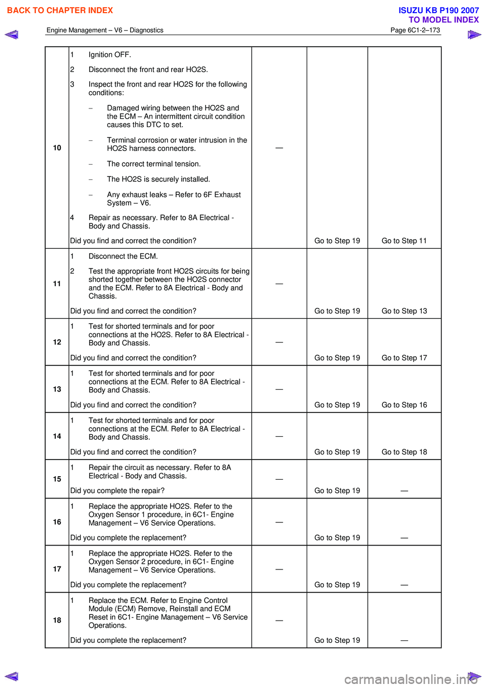
10 1 Ignition OFF.
2 Disconnect the front and rear HO2S.
3 Inspect the front and rear HO2S for the following conditions:
− Damaged wiring between the HO2S and
the ECM – An intermittent circuit condition
causes this DTC to set.
− Terminal corrosion or water intrusion in the
HO2S harness connectors.
− The correct terminal tension.
− The HO2S is securely installed.
− Any exhaust leaks – Refer to 6F Exhaust
System – V6.
4 Repair as necessary. Refer to 8A Electrical - Body and Chassis.
Did you find and correct the condition? —
Go to Step 19 Go to Step 11
11 1 Disconnect the ECM.
2 Test the appropriate front HO2S circuits for being shorted together between the HO2S connector
and the ECM. Refer to 8A Electrical - Body and
Chassis.
Did you find and correct the condition? —
Go to Step 19 Go to Step 13
12 1 Test for shorted terminals and for poor
connections at the HO2S. Refer to 8A Electrical -
Body and Chassis.
Did you find and correct the condition? —
Go to Step 19 Go to Step 17
13 1 Test for shorted terminals and for poor
connections at the ECM. Refer to 8A Electrical -
Body and Chassis.
Did you find and correct the condition? —
Go to Step 19 Go to Step 16
14 1 Test for shorted terminals and for poor
connections at the ECM. Refer to 8A Electrical -
Body and Chassis.
Did you find and correct the condition? —
Go to Step 19 Go to Step 18
15 1 Repair the circuit as necessary. Refer to 8A
Electrical - Body and Chassis.
Did you complete the repair? —
Go to Step 19 —
16 1 Replace the appropriate HO2S. Refer to the
Oxygen Sensor 1 procedure, in 6C1- Engine
Management – V6 Service Operations.
Did you complete the replacement? —
Go to Step 19 —
17 1 Replace the appropriate HO2S. Refer to the
Oxygen Sensor 2 procedure, in 6C1- Engine
Management – V6 Service Operations.
Did you complete the replacement? —
Go to Step 19 —
18 1 Replace the ECM. Refer to Engine Control
Module (ECM) Remove, Reinstall and ECM
Reset in 6C1- Engine Management – V6 Service
Operations.
Did you complete the replacement? —
Go to Step 19 —
BACK TO CHAPTER INDEX
TO MODEL INDEX
ISUZU KB P190 2007
Page 3454 of 6020
Engine Management – V6 – Diagnostics Page 6C1-2–176
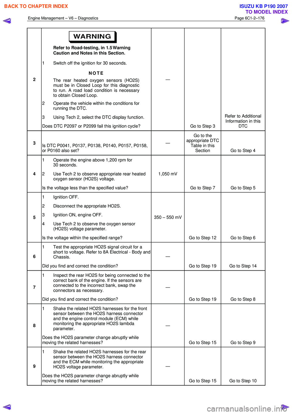
2 Refer to Road-testing, in 1.5 Warning
Caution and Notes in this Section.
1 Switch off the ignition for 30 seconds.
NOTE
The rear heated oxygen sensors (HO2S)
must be in Closed Loop for this diagnostic
to run. A road load condition is necessary
to obtain Closed Loop.
2 Operate the vehicle within the conditions for running the DTC.
3 Using Tech 2, select the DTC display function.
Does DTC P2097 or P2099 fail this ignition cycle? —
Go to Step 3 Refer to Additional
Information in this DTC
3 Is DTC P0041, P0137, P0138, P0140, P0157, P0158,
or P0160 also set? —
Go to the
appropriate DTC Table in this Section Go to Step 4
4 1 Operate the engine above 1,200 rpm for
30 seconds.
2 Use Tech 2 to observe appropriate rear heated oxygen sensor (HO2S) voltage.
Is the voltage less than the specified value? 1,050 mV
Go to Step 7 Go to Step 5
5 1 Ignition OFF.
2 Disconnect the appropriate HO2S.
3 Ignition ON, engine OFF.
4 Use Tech 2 to observe the oxygen sensor (HO2S) voltage parameter.
Is the voltage within the specified range? 350 – 550 mV
Go to Step 12 Go to Step 6
6 1 Test the appropriate HO2S signal circuit for a
short to voltage. Refer to 8A Electrical - Body and
Chassis.
Did you find and correct the condition? —
Go to Step 19 Go to Step 14
7 1 Inspect the rear HO2S for being connected to the
correct bank of the engine. If the sensors are
connected to the incorrect bank, swap the
connectors as necessary.
Did you find and correct the condition? —
Go to Step 19 Go to Step 8
8 1 Shake the related HO2S harnesses for the front
sensor between the HO2S harness connector
and the engine control module (ECM) while
monitoring the appropriate HO2S lambda
parameter.
Does the HO2S parameter change abruptly while
moving the related harnesses? —
Go to Step 15 Go to Step 9
9 1 Shake the related HO2S harnesses for the rear
sensor between the HO2S harness connector
and the ECM while monitoring the appropriate
HO2S voltage parameter.
Does the HO2S parameter change abruptly while
moving the related harnesses? —
Go to Step 15 Go to Step 10
BACK TO CHAPTER INDEX
TO MODEL INDEX
ISUZU KB P190 2007
Page 3455 of 6020
Engine Management – V6 – Diagnostics Page 6C1-2–177
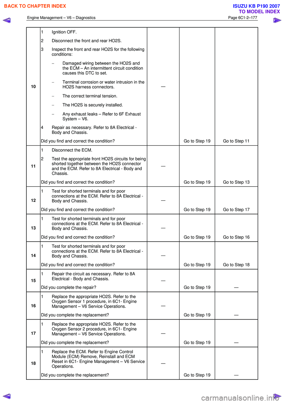
10 1 Ignition OFF.
2 Disconnect the front and rear HO2S.
3 Inspect the front and rear HO2S for the following conditions:
− Damaged wiring between the HO2S and
the ECM – An intermittent circuit condition
causes this DTC to set.
− Terminal corrosion or water intrusion in the
HO2S harness connectors.
− The correct terminal tension.
− The HO2S is securely installed.
− Any exhaust leaks – Refer to 6F Exhaust
System – V6.
4 Repair as necessary. Refer to 8A Electrical - Body and Chassis.
Did you find and correct the condition? —
Go to Step 19 Go to Step 11
11 1 Disconnect the ECM.
2 Test the appropriate front HO2S circuits for being shorted together between the HO2S connector
and the ECM. Refer to 8A Electrical - Body and
Chassis.
Did you find and correct the condition? —
Go to Step 19 Go to Step 13
12 1 Test for shorted terminals and for poor
connections at the ECM. Refer to 8A Electrical -
Body and Chassis.
Did you find and correct the condition? —
Go to Step 19 Go to Step 17
13 1 Test for shorted terminals and for poor
connections at the ECM. Refer to 8A Electrical -
Body and Chassis.
Did you find and correct the condition? —
Go to Step 19 Go to Step 16
14 1 Test for shorted terminals and for poor
connections at the ECM. Refer to 8A Electrical -
Body and Chassis.
Did you find and correct the condition? —
Go to Step 19 Go to Step 18
15 1 Repair the circuit as necessary. Refer to 8A
Electrical - Body and Chassis.
Did you complete the repair? —
Go to Step 19 —
16 1 Replace the appropriate HO2S. Refer to the
Oxygen Sensor 1 procedure, in 6C1- Engine
Management – V6 Service Operations.
Did you complete the replacement? —
Go to Step 19 —
17 1 Replace the appropriate HO2S. Refer to the
Oxygen Sensor 2 procedure, in 6C1- Engine
Management – V6 Service Operations.
Did you complete the replacement? —
Go to Step 19 —
18 1 Replace the ECM. Refer to Engine Control
Module (ECM) Remove, Reinstall and ECM
Reset in 6C1- Engine Management – V6 Service
Operations.
Did you complete the replacement? —
Go to Step 19 —
BACK TO CHAPTER INDEX
TO MODEL INDEX
ISUZU KB P190 2007
Page 3464 of 6020
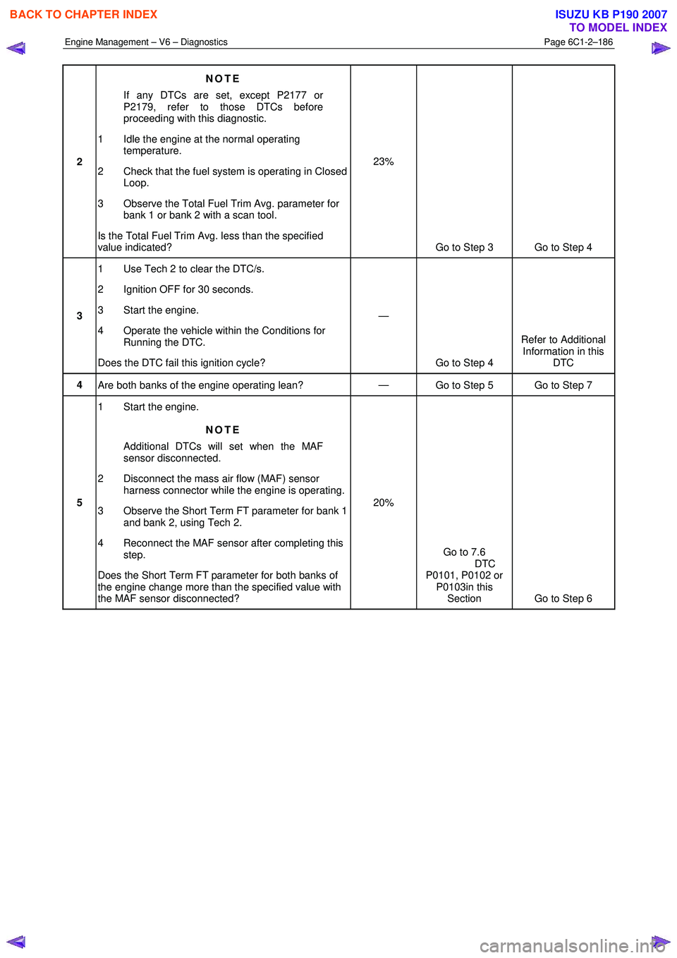
Engine Management – V6 – Diagnostics Page 6C1-2–186
2 NOTE
If any DTCs are set, except P2177 or
P2179, refer to those DTCs before
proceeding with this diagnostic.
1 Idle the engine at the normal operating temperature.
2 Check that the fuel system is operating in Closed Loop.
3 Observe the Total Fuel Trim Avg. parameter for bank 1 or bank 2 with a scan tool.
Is the Total Fuel Trim Avg. less than the specified
value indicated? 23%
Go to Step 3 Go to Step 4
3 1 Use Tech 2 to clear the DTC/s.
2 Ignition OFF for 30 seconds.
3 Start the engine.
4 Operate the vehicle within the Conditions for Running the DTC.
Does the DTC fail this ignition cycle? —
Go to Step 4 Refer to Additional
Information in this DTC
4 Are both banks of the engine operating lean? —
Go to Step 5 Go to Step 7
5 1 Start the engine.
NOTE
Additional DTCs will set when the MAF
sensor disconnected.
2 Disconnect the mass air flow (MAF) sensor harness connector while the engine is operating.
3 Observe the Short Term FT parameter for bank 1 and bank 2, using Tech 2.
4 Reconnect the MAF sensor after completing this step.
Does the Short Term FT parameter for both banks of
the engine change more than the specified value with
the MAF sensor disconnected? 20%
Go to 7.6
DTC
P0101, P0102 or P0103in this Section Go to Step 6
BACK TO CHAPTER INDEX
TO MODEL INDEX
ISUZU KB P190 2007
Page 3468 of 6020
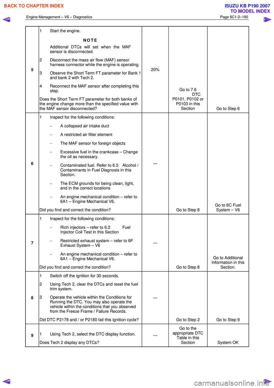
Engine Management – V6 – Diagnostics Page 6C1-2–190
5 1 Start the engine.
NOTE
Additional DTCs will set when the MAF
sensor is disconnected.
2 Disconnect the mass air flow (MAF) sensor harness connector while the engine is operating.
3 Observe the Short Term FT parameter for Bank 1 and bank 2 with Tech 2.
4 Reconnect the MAF sensor after completing this step.
Does the Short Term FT parameter for both banks of
the engine change more than the specified value with
the MAF sensor disconnected? 20%
Go to 7.6
DTC
P0101, P0102 or P0103 in this Section Go to Step 6
6 1 Inspect for the following conditions:
− A collapsed air intake duct
− A restricted air filter element
− The MAF sensor for foreign objects
− Excessive fuel in the crankcase – Change
the oil as necessary.
− Contaminated fuel. Refer to 6.5 Alcohol /
Contaminants in Fuel Diagnosis in this
Section.
− The ECM grounds for being clean, tight,
and in the correct locations
− An engine mechanical condition – refer to
6A1 – Engine Mechanical V6.
Did you find and correct the condition? —
Go to Step 8 Go to 6C Fuel
System – V6
7 1 Inspect for the following conditions:
− Rich injectors – refer to 6.2 Fuel
Injector Coil Test in this Section
− Restricted exhaust system – refer to 6F
Exhaust System – V6
− An engine mechanical condition – refer to
6A1 – Engine Mechanical V6.
Did you find and correct the condition? —
Go to Step 8 Go to Additional
Information in this Section.
8 1 Switch off the ignition for 30 seconds.
2 Using Tech 2, clear the DTCs and reset the fuel trim system.
3 Operate the vehicle within the Conditions for Running the DTC. You may also operate the
vehicle within the conditions that you observed
from the Freeze Frame / Failure Records.
Did DTC P2178 and / or P2180 fail this ignition cycle? —
Go to Step 2 Go to Step 9
9 1 Using Tech 2, select the DTC display function.
Does Tech 2 display any DTCs? —
Go to the
appropriate DTC Table in this Section System OK
BACK TO CHAPTER INDEX
TO MODEL INDEX
ISUZU KB P190 2007
Page 3471 of 6020
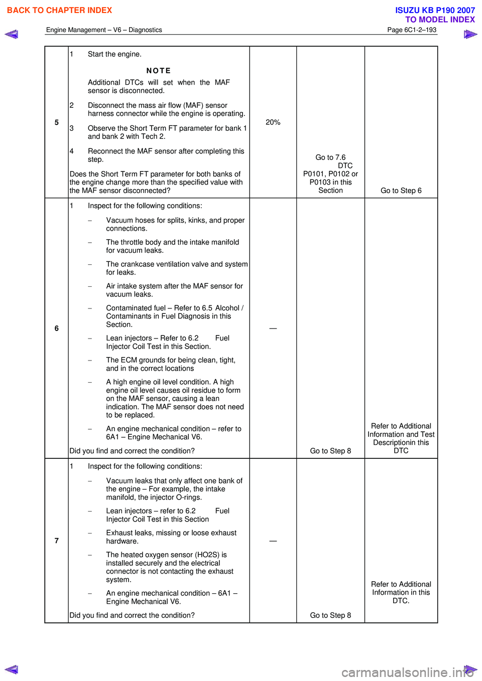
Engine Management – V6 – Diagnostics Page 6C1-2–193
5 1 Start the engine.
NOTE
Additional DTCs will set when the MAF
sensor is disconnected.
2 Disconnect the mass air flow (MAF) sensor harness connector while the engine is operating.
3 Observe the Short Term FT parameter for bank 1 and bank 2 with Tech 2.
4 Reconnect the MAF sensor after completing this step.
Does the Short Term FT parameter for both banks of
the engine change more than the specified value with
the MAF sensor disconnected? 20%
Go to 7.6
DTC
P0101, P0102 or P0103 in this Section Go to Step 6
6 1 Inspect for the following conditions:
− Vacuum hoses for splits, kinks, and proper
connections.
− The throttle body and the intake manifold
for vacuum leaks.
− The crankcase ventilation valve and system
for leaks.
− Air intake system after the MAF sensor for
vacuum leaks.
− Contaminated fuel – Refer to 6.5 Alcohol /
Contaminants in Fuel Diagnosis in this
Section.
− Lean injectors – Refer to 6.2 Fuel
Injector Coil Test in this Section.
− The ECM grounds for being clean, tight,
and in the correct locations
− A high engine oil level condition. A high
engine oil level causes oil residue to form
on the MAF sensor, causing a lean
indication. The MAF sensor does not need
to be replaced.
− An engine mechanical condition – refer to
6A1 – Engine Mechanical V6.
Did you find and correct the condition? —
Go to Step 8 Refer to Additional
Information and Test Descriptionin this DTC
7 1 Inspect for the following conditions:
− Vacuum leaks that only affect one bank of
the engine – For example, the intake
manifold, the injector O-rings.
− Lean injectors – refer to 6.2 Fuel
Injector Coil Test in this Section
− Exhaust leaks, missing or loose exhaust
hardware.
− The heated oxygen sensor (HO2S) is
installed securely and the electrical
connector is not contacting the exhaust
system.
− An engine mechanical condition – 6A1 –
Engine Mechanical V6.
Did you find and correct the condition? —
Go to Step 8 Refer to Additional
Information in this DTC.
BACK TO CHAPTER INDEX
TO MODEL INDEX
ISUZU KB P190 2007
Page 3474 of 6020
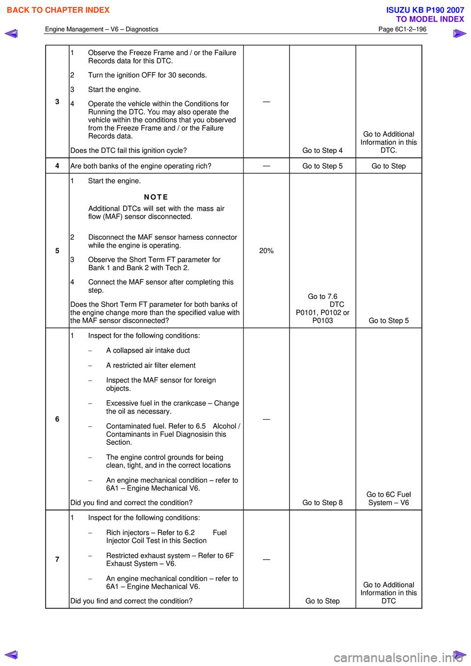
Engine Management – V6 – Diagnostics Page 6C1-2–196
3 1 Observe the Freeze Frame and / or the Failure
Records data for this DTC.
2 Turn the ignition OFF for 30 seconds.
3 Start the engine.
4 Operate the vehicle within the Conditions for Running the DTC. You may also operate the
vehicle within the conditions that you observed
from the Freeze Frame and / or the Failure
Records data.
Does the DTC fail this ignition cycle? —
Go to Step 4 Go to Additional
Information in this DTC.
4 Are both banks of the engine operating rich? —
Go to Step 5 Go to Step
5 1 Start the engine.
NOTE
Additional DTCs will set with the mass air
flow (MAF) sensor disconnected.
2 Disconnect the MAF sensor harness connector while the engine is operating.
3 Observe the Short Term FT parameter for Bank 1 and Bank 2 with Tech 2.
4 Connect the MAF sensor after completing this step.
Does the Short Term FT parameter for both banks of
the engine change more than the specified value with
the MAF sensor disconnected? 20%
Go to 7.6
DTC
P0101, P0102 or P0103 Go to Step 5
6 1 Inspect for the following conditions:
− A collapsed air intake duct
− A restricted air filter element
− Inspect the MAF sensor for foreign
objects.
− Excessive fuel in the crankcase – Change
the oil as necessary.
− Contaminated fuel. Refer to 6.5 Alcohol /
Contaminants in Fuel Diagnosisin this
Section.
− The engine control grounds for being
clean, tight, and in the correct locations
− An engine mechanical condition – refer to
6A1 – Engine Mechanical V6.
Did you find and correct the condition? —
Go to Step 8 Go to 6C Fuel
System – V6
7 1 Inspect for the following conditions:
− Rich injectors – Refer to 6.2 Fuel
Injector Coil Test in this Section
− Restricted exhaust system – Refer to 6F
Exhaust System – V6.
− An engine mechanical condition – refer to
6A1 – Engine Mechanical V6.
Did you find and correct the condition? —
Go to Step Go to Additional
Information in this DTC
BACK TO CHAPTER INDEX
TO MODEL INDEX
ISUZU KB P190 2007