2007 ISUZU KB P190 Harness
[x] Cancel search: HarnessPage 3653 of 6020
Battery Page 6D1-3–13
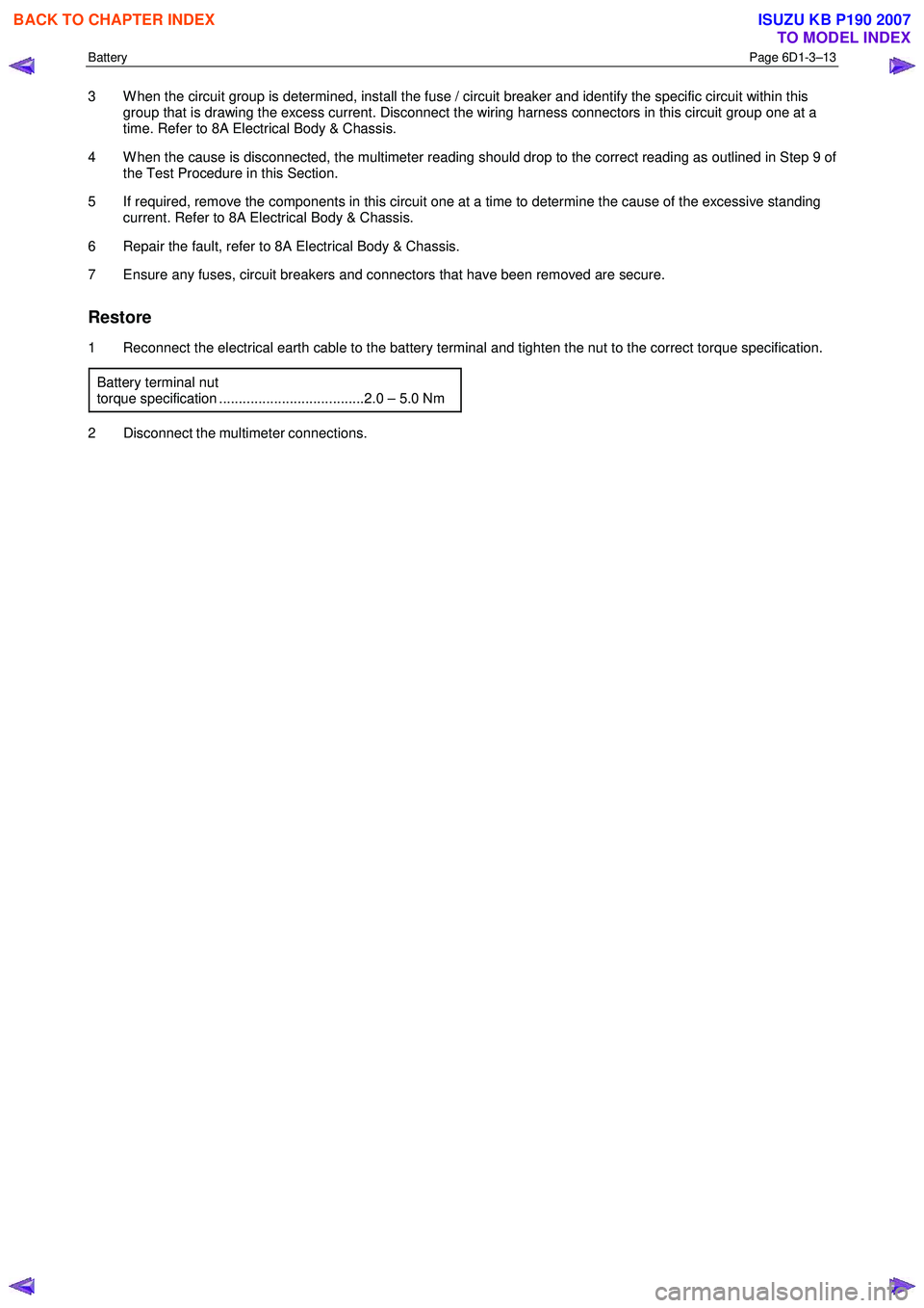
3 W hen the circuit group is determined, install the fuse / circuit breaker and identify the specific circuit within this
group that is drawing the excess current. Disconnect the wiring harness connectors in this circuit group one at a
time. Refer to 8A Electrical Body & Chassis.
4 W hen the cause is disconnected, the multimeter reading should drop to the correct reading as outlined in Step 9 of the Test Procedure in this Section.
5 If required, remove the components in this circuit one at a time to determine the cause of the excessive standing current. Refer to 8A Electrical Body & Chassis.
6 Repair the fault, refer to 8A Electrical Body & Chassis.
7 Ensure any fuses, circuit breakers and connectors that have been removed are secure.
Restore
1 Reconnect the electrical earth cable to the battery terminal and tighten the nut to the correct torque specification.
Battery terminal nut
torque specification .....................................2.0 – 5.0 Nm
2 Disconnect the multimeter connections.
BACK TO CHAPTER INDEX
TO MODEL INDEX
ISUZU KB P190 2007
Page 3677 of 6020
Powertrain Interface Module – V6 Page 6E1–16
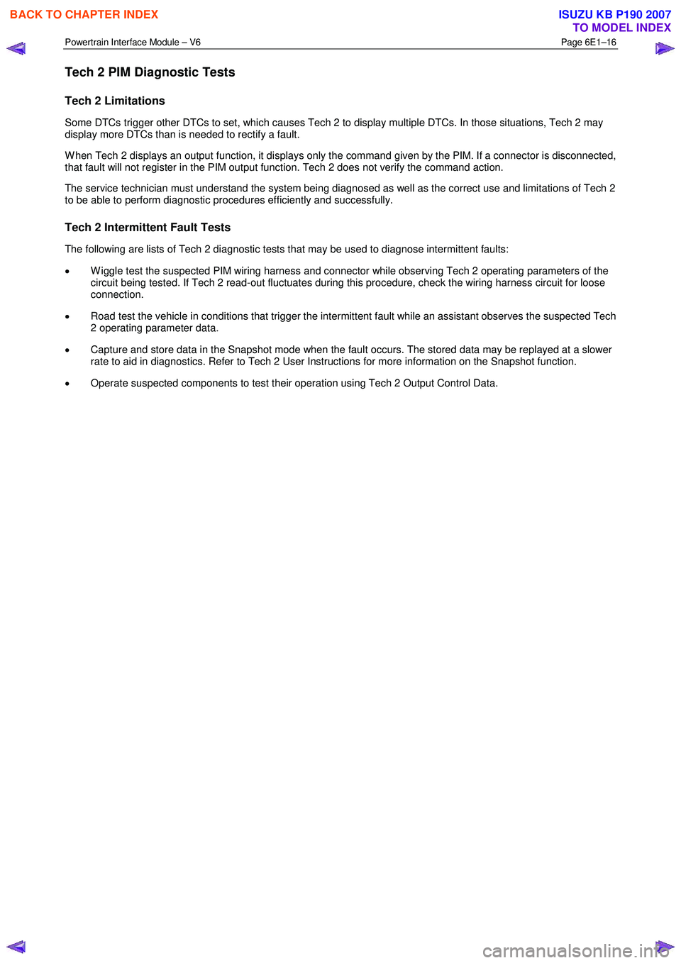
Tech 2 PIM Diagnostic Tests
Tech 2 Limitations
Some DTCs trigger other DTCs to set, which causes Tech 2 to display multiple DTCs. In those situations, Tech 2 may
display more DTCs than is needed to rectify a fault.
W hen Tech 2 displays an output function, it displays only the command given by the PIM. If a connector is disconnected,
that fault will not register in the PIM output function. Tech 2 does not verify the command action.
The service technician must understand the system being diagnosed as well as the correct use and limitations of Tech 2
to be able to perform diagnostic procedures efficiently and successfully.
Tech 2 Intermittent Fault Tests
The following are lists of Tech 2 diagnostic tests that may be used to diagnose intermittent faults:
• W iggle test the suspected PIM wiring harness and connector while observing Tech 2 operating parameters of the
circuit being tested. If Tech 2 read-out fluctuates during this procedure, check the wiring harness circuit for loose
connection.
• Road test the vehicle in conditions that trigger the intermittent fault while an assistant observes the suspected Tech
2 operating parameter data.
• Capture and store data in the Snapshot mode when the fault occurs. The stored data may be replayed at a slower
rate to aid in diagnostics. Refer to Tech 2 User Instructions for more information on the Snapshot function.
• Operate suspected components to test their operation using Tech 2 Output Control Data.
BACK TO CHAPTER INDEX
TO MODEL INDEX
ISUZU KB P190 2007
Page 3686 of 6020
Powertrain Interface Module – V6 Page 6E1–25
• Thorough inspection of the wiring circuits and connectors listed in the diagnostic procedures must be performed,
otherwise misdiagnosis may occur.
• Inspect the electrical circuitry or connector terminals that are suspected to be causing the complaint for the
following conditions:
• backed-out connector terminals,
• improper wiring connector mating,
• broken wiring connector locks,
• damaged connector terminals, and
• physical damage to the wiring harness.
• Before replacing a component, inspect its connector terminal for corrosion or deformation that may cause the fault
condition.
Preliminary Checks
The PIM preliminary check examines easily accessible components which may cause problems with the PIM. This visual
and physical inspection procedure may quickly identify the fault condition and eliminate the need for additional diagnosis.
• Refer to Service Techlines for relevant information regarding the fault condition.
• Ensure the battery is fully charged.
• Check the battery connections for corrosion or a loose terminal.
• Perform a visual and physical inspection of the following:
• PIM component wiring harness and terminals for proper connections, pinches or cuts, and
• PIM wiring harness routing which may be positioned very close to a high voltage or high current devices such
as aftermarket audio systems.
NOTE
High voltage or high current devices may induce
electrical noise on a circuit, which can interfere
with normal circuit operation.
• The PIM is sensitive to Electro Magnetic Interference (EMI). Check for incorrect aftermarket theft deterrent
devices, lights or mobile phone installations if an intermittent malfunction is suspected.
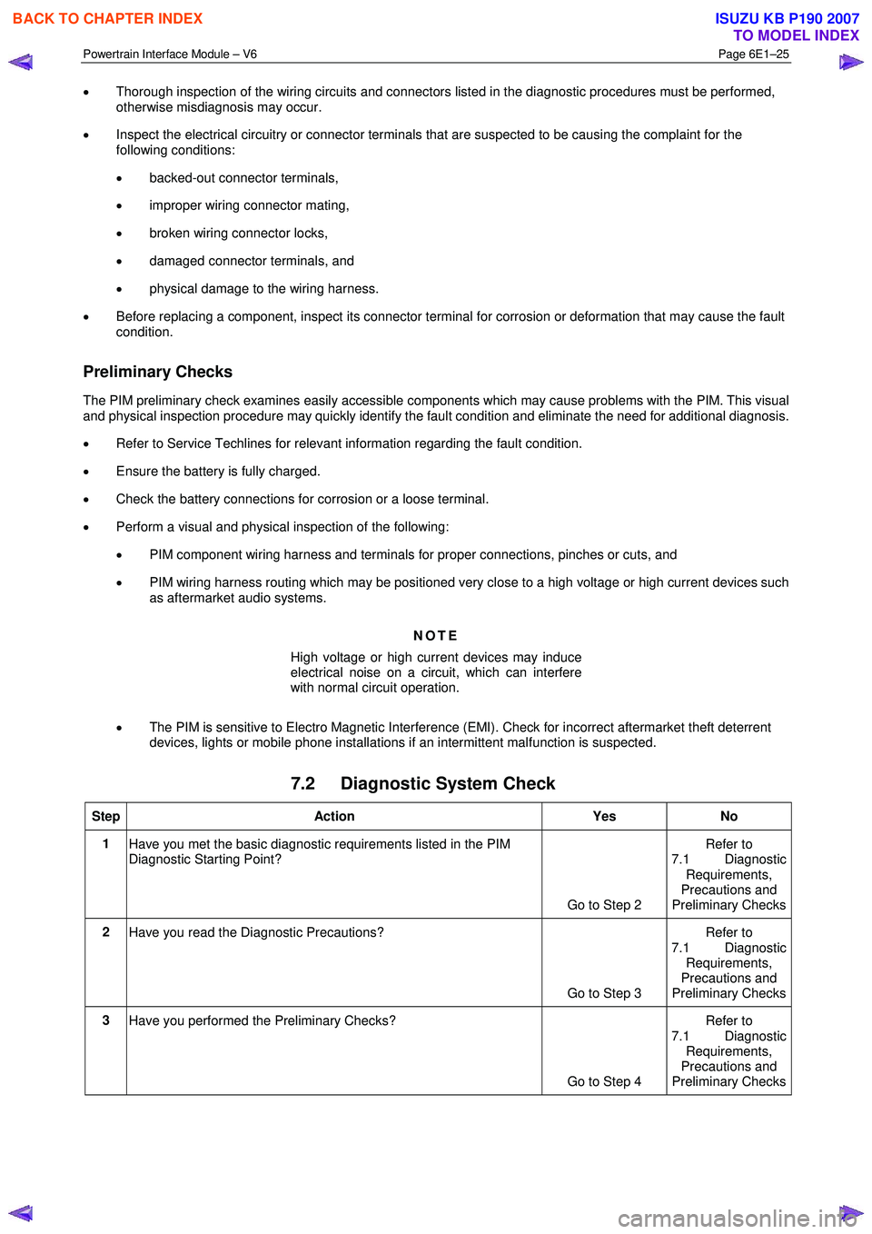
7.2 Diagnostic System Check
Step Action Yes No
1
Have you met the basic diagnostic requirements listed in the PIM
Diagnostic Starting Point?
Go to Step 2 Refer to
7.1 Diagnostic
Requirements,
Precautions and
Preliminary Checks
2 Have you read the Diagnostic Precautions?
Go to Step 3 Refer to
7.1 Diagnostic Requirements,
Precautions and
Preliminary Checks
3 Have you performed the Preliminary Checks?
Go to Step 4 Refer to
7.1 Diagnostic Requirements,
Precautions and
Preliminary Checks
BACK TO CHAPTER INDEX
TO MODEL INDEX
ISUZU KB P190 2007
Page 3688 of 6020
Powertrain Interface Module – V6 Page 6E1–27
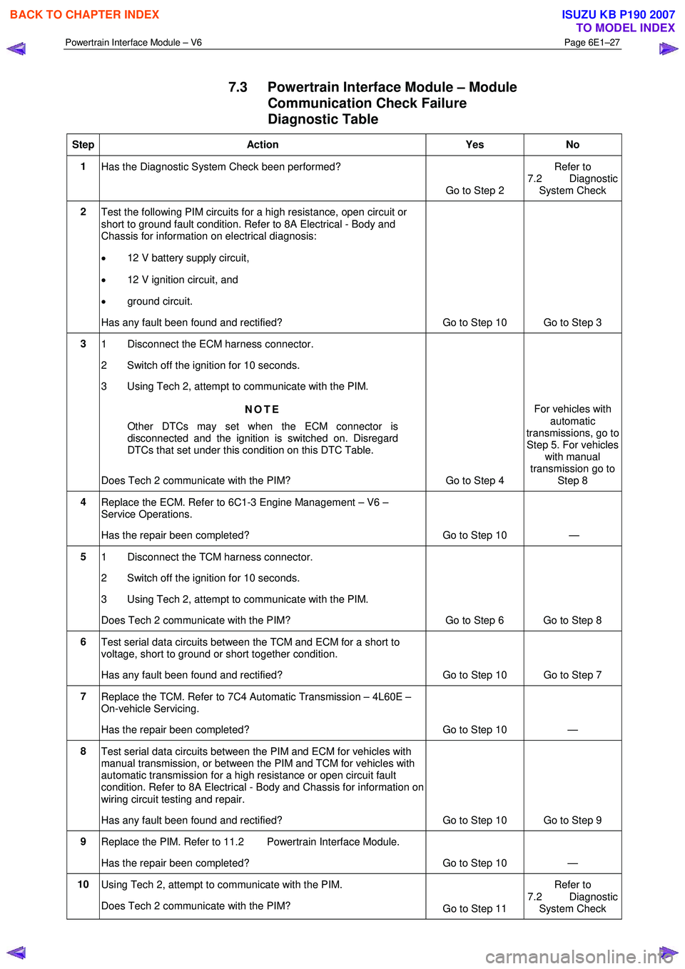
7.3 Powertrain Interface Module – Module
Communication Check Failure
Diagnostic Table
Step Action Yes No
1
Has the Diagnostic System Check been performed?
Go to Step 2 Refer to
7.2 Diagnostic System Check
2 Test the following PIM circuits for a high resistance, open circuit or
short to ground fault condition. Refer to 8A Electrical - Body and
Chassis for information on electrical diagnosis:
• 12 V battery supply circuit,
• 12 V ignition circuit, and
• ground circuit.
Has any fault been found and rectified? Go to Step 10 Go to Step 3
3 1 Disconnect the ECM harness connector.
2 Switch off the ignition for 10 seconds.
3 Using Tech 2, attempt to communicate with the PIM.
NOTE
Other DTCs may set when the ECM connector is
disconnected and the ignition is switched on. Disregard
DTCs that set under this condition on this DTC Table.
Does Tech 2 communicate with the PIM? Go to Step 4 For vehicles with
automatic
transmissions, go to
Step 5. For vehicles with manual
transmission go to Step 8
4 Replace the ECM. Refer to 6C1-3 Engine Management – V6 –
Service Operations.
Has the repair been completed? Go to Step 10 —
5 1 Disconnect the TCM harness connector.
2 Switch off the ignition for 10 seconds.
3 Using Tech 2, attempt to communicate with the PIM.
Does Tech 2 communicate with the PIM? Go to Step 6 Go to Step 8
6 Test serial data circuits between the TCM and ECM for a short to
voltage, short to ground or short together condition.
Has any fault been found and rectified? Go to Step 10 Go to Step 7
7 Replace the TCM. Refer to 7C4 Automatic Transmission – 4L60E –
On-vehicle Servicing.
Has the repair been completed? Go to Step 10 —
8 Test serial data circuits between the PIM and ECM for vehicles with
manual transmission, or between the PIM and TCM for vehicles with
automatic transmission for a high resistance or open circuit fault
condition. Refer to 8A Electrical - Body and Chassis for information on
wiring circuit testing and repair.
Has any fault been found and rectified? Go to Step 10 Go to Step 9
9 Replace the PIM. Refer to 11.2 Powertrain Interface Module.
Has the repair been completed? Go to Step 10 —
10 Using Tech 2, attempt to communicate with the PIM.
Does Tech 2 communicate with the PIM? Go to Step 11 Refer to
7.2 Diagnostic System Check
BACK TO CHAPTER INDEX
TO MODEL INDEX
ISUZU KB P190 2007
Page 3690 of 6020

Powertrain Interface Module – V6 Page 6E1–29
Intermittent Fault Conditions
8.1 Intermittent Conditions Diagnostic Table
Description
A fault condition is intermittent if one of the following conditions exists:
• The fault condition is not always present.
• The fault condition cannot be presently duplicated.
• There is no Current DTC but a History DTC is stored.
Diagnostic Table
Checks Actions
Preliminary
• Perform the Preliminary Checks, refer to 7.1 Diagnostic Requirements,
Precautions and Preliminary Checks.
• Gather information from the customer regarding the conditions that trigger the
intermittent fault such as:
• At what engine or ambient temperature range does the fault occur?
• Does the fault occur when operating aftermarket electrical equipment inside
the vehicle?
• Does the fault occur on rough roads or in wet road conditions?
• If the intermittent fault is a start and then stall condition, check immobiliser system.
Refer to 11A Immobiliser.
Harness / Connector Install Tech 2 and perform the Tech 2 Intermittent Fault Tests. Refer to 4.1 Diagnostic General Descriptions for information on Tech 2 ECU diagnostic
tests.
W arning Indicator The following conditions may cause an intermittent Malfunction Indicator Lamp fault with
no DTC listed:
• Electromagnetic Interference (EMI) caused by a faulty relay, ECM controlled
solenoid, switch or other external source.
• Incorrect installation of aftermarket electrical equipment such as the following:
• mobile phones,
• theft deterrent alarms,
• lights, or
• radio equipment.
• Loose PIM ground connections.
BACK TO CHAPTER INDEX
TO MODEL INDEX
ISUZU KB P190 2007
Page 3695 of 6020
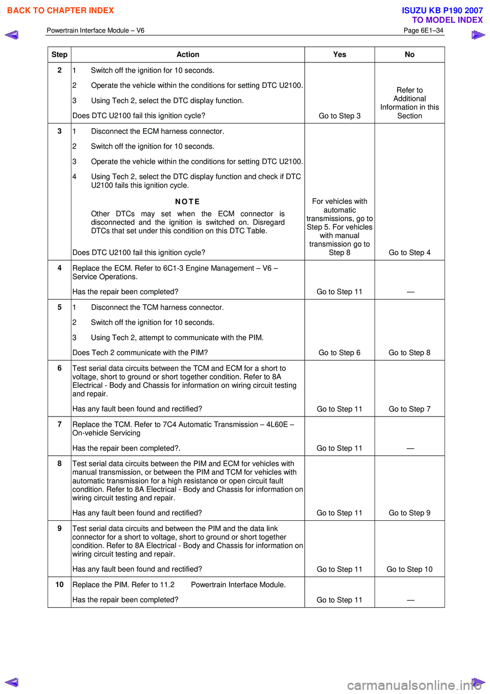
Powertrain Interface Module – V6 Page 6E1–34
Step Action Yes No
2
1 Switch off the ignition for 10 seconds.
2 Operate the vehicle within the conditions for setting DTC U2100.
3 Using Tech 2, select the DTC display function.
Does DTC U2100 fail this ignition cycle? Go to Step 3 Refer to
Additional
Information in this
Section
3 1 Disconnect the ECM harness connector.
2 Switch off the ignition for 10 seconds.
3 Operate the vehicle within the conditions for setting DTC U2100.
4 Using Tech 2, select the DTC display function and check if DTC U2100 fails this ignition cycle.
NOTE
Other DTCs may set when the ECM connector is
disconnected and the ignition is switched on. Disregard
DTCs that set under this condition on this DTC Table.
Does DTC U2100 fail this ignition cycle? For vehicles with
automatic
transmissions, go to Step 5. For vehicles
with manual
transmission go to Step 8 Go to Step 4
4
Replace the ECM. Refer to 6C1-3 Engine Management – V6 –
Service Operations.
Has the repair been completed? Go to Step 11 —
5 1 Disconnect the TCM harness connector.
2 Switch off the ignition for 10 seconds.
3 Using Tech 2, attempt to communicate with the PIM.
Does Tech 2 communicate with the PIM? Go to Step 6 Go to Step 8
6 Test serial data circuits between the TCM and ECM for a short to
voltage, short to ground or short together condition. Refer to 8A
Electrical - Body and Chassis for information on wiring circuit testing
and repair.
Has any fault been found and rectified? Go to Step 11 Go to Step 7
7
Replace the TCM. Refer to 7C4 Automatic Transmission – 4L60E –
On-vehicle Servicing
Has the repair been completed?. Go to Step 11 —
8 Test serial data circuits between the PIM and ECM for vehicles with
manual transmission, or between the PIM and TCM for vehicles with
automatic transmission for a high resistance or open circuit fault
condition. Refer to 8A Electrical - Body and Chassis for information on
wiring circuit testing and repair.
Has any fault been found and rectified? Go to Step 11 Go to Step 9
9 Test serial data circuits and between the PIM and the data link
connector for a short to voltage, short to ground or short together
condition. Refer to 8A Electrical - Body and Chassis for information on
wiring circuit testing and repair.
Has any fault been found and rectified? Go to Step 11 Go to Step 10
10
Replace the PIM. Refer to 11.2 Powertrain Interface Module.
Has the repair been completed? Go to Step 11 —
BACK TO CHAPTER INDEX
TO MODEL INDEX
ISUZU KB P190 2007
Page 3698 of 6020

Powertrain Interface Module – V6 Page 6E1–37
Step Action Yes No
6
1 Disconnect the PIM harness connector (vehicles with manual
transmission), or TCM harness connector (vehicles with
automatic transmission).
2 Using a digital multimeter, measure the resistance between the two CAN_LO terminals of either the PIM or TCM.
NOTE
Refer to 5 GM LAN Serial Communication Circuit and
6 Wiring Diagram and Connector for the appropriate GM
LAN component terminal identification.
Does the digital multimeter display infinity? Go to Step 8 Go to Step 7
7
Using a digital multimeter, measure the resistance between the two
CAN_HI terminals of either the PIM (vehicles with manual
transmission) or TCM (vehicles with automatic transmission).
Does the digital multimeter display infinity? Go to Step 8 Go to Step 9
8
Replace the PIM (vehicles with manual transmission) or TCM
(vehicles with automatic transmission). Refer to one of the following
for the component replacement procedure:
• 7C4 Automatic Transmission – 4L60E – On-vehicle Servicing, or
• 11.2 Powertrain Interface Module.
Has the repair been completed? Go to Step 11 —
9 Replace the ECM. Refer to 6C1-3 Engine Management – V6 –
Service Operations.
Has the repair been completed? Go to Step 11
—
10
Replace the PIM. Refer to 11.2 Powertrain Interface Module.
Has the repair been completed? Go to Step 11 —
11 1 Using Tech 2, clear the DTCs.
2 Switch off the ignition for 30 seconds.
3 Start the engine.
4 Operate the vehicle within the conditions for running the DTC.
Does DTC U2105 fail this ignition cycle? Go to Step 2 Go to Step 12
12
Using Tech 2, select the DTC display function.
Does Tech 2 display any DTCs? Go to the
appropriate DTC Table System OK
When all diagnosis and repairs are completed, clear all DTCs and check the system for correct operation.
BACK TO CHAPTER INDEX
TO MODEL INDEX
ISUZU KB P190 2007
Page 3700 of 6020

Powertrain Interface Module – V6 Page 6E1–39
6 This step tests the internal GM LAN CAN_HI circuit in the PIM.
7 This step tests the internal GM LAN CAN_LO circuit in the PIM.
DTC U2106 Diagnostic Table
Step Action Yes No
1
Has the Diagnostic System Check been performed?
Go to Step 2 Refer to
7.2 Diagnostic
System Check
2 1 Switch off the ignition for 10 seconds.
2 Operate the vehicle within the conditions for setting DTC U2106.
3 Using Tech 2, select the DTC display function.
Does DTC U2106 fail this ignition cycle? Go to Step 3 Refer to
Additional
Information in this Section
3 Using Tech 2, attempt to communicate with the TCM.
Does Tech 2 communicate with the TCM? Go to Step 9 Go to Step 4
4 Test the following TCM circuits for a high resistance, open circuit or
short to ground fault condition. Refer to 8A Electrical - Body and
Chassis for information on electrical diagnosis:
• 12 V battery supply voltage circuit,
• 12 V accessory supply circuit,
• Ignition Control Relay 12 V supply circuit, and
• all TCM ground connections.
Has any fault been found and rectified? Go to Step 10 Go to Step 5
5 Test serial data circuits between the TCM and PIM for a high
resistance or open circuit fault condition. Refer to 8A Electrical - Body
and Chassis for information on wiring circuit testing and repair.
Has any fault been found and rectified? Go to Step 10 Go to Step 6
6 1 Disconnect the PIM harness connector.
2 Using a digital multimeter, measure the resistance between the two CAN_LO terminals of the PIM.
NOTE
Refer to 5 GM LAN Serial Communication Circuit and
6 Wiring Diagram and Connector for the appropriate GM
LAN component terminal identification.
Does the digital multimeter display infinity? Go to Step 9 Go to Step 7
7
Using a digital multimeter, measure the resistance between the two
CAN_HI terminals of the PIM.
Does the digital multimeter display infinity? Go to Step 9 Go to Step 8
8
Replace the TCM. Refer to 7C4 Automatic Transmission – 4L60E –
On-vehicle Servicing.
Has the repair been completed? Go to Step 10 —
9 Replace the PIM. Refer to 11.2 Powertrain Interface Module.
Has the repair been completed? Go to Step 10 —
BACK TO CHAPTER INDEX
TO MODEL INDEX
ISUZU KB P190 2007