2007 ISUZU KB P190 air condition
[x] Cancel search: air conditionPage 2680 of 6020
Engine Mechanical – V6 Page 6A1–201
Inspect
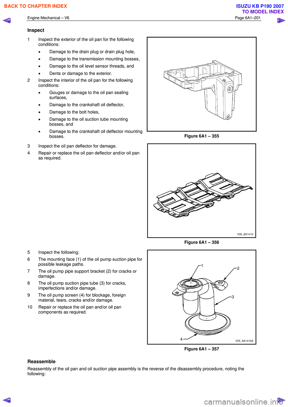
1 Inspect the exterior of the oil pan for the following
conditions:
• Damage to the drain plug or drain plug hole,
• Damage to the transmission mounting bosses,
• Damage to the oil level sensor threads, and
• Dents or damage to the exterior.
2 Inspect the interior of the oil pan for the following conditions:
• Gouges or damage to the oil pan sealing
surfaces,
• Damage to the crankshaft oil deflector,
• Damage to the bolt holes,
• Damage to the oil suction tube mounting
bosses, and
• Damage to the crankshaft oil deflector mounting
bosses.
Figure 6A1 – 355
3 Inspect the oil pan deflector for damage.
4 Repair or replace the oil pan deflector and/or oil pan as required.
Figure 6A1 – 356
5 Inspect the following:
6 The mounting face (1) of the oil pump suction pipe for possible leakage paths.
7 The oil pump pipe support bracket (2) for cracks or damage.
8 The oil pump suction pipe tube (3) for cracks, imperfections and/or damage.
9 The oil pump screen (4) for blockage, foreign material, tears, cracks and/or damage.
10 Repair or replace the oil pan and/or oil pan components as required.
Figure 6A1 – 357
Reassemble
Reassembly of the oil pan and oil suction pipe assembly is the reverse of the disassembly procedure, noting the
following:
BACK TO CHAPTER INDEX
TO MODEL INDEX
ISUZU KB P190 2007
Page 2683 of 6020
Engine Mechanical – V6 Page 6A1–204
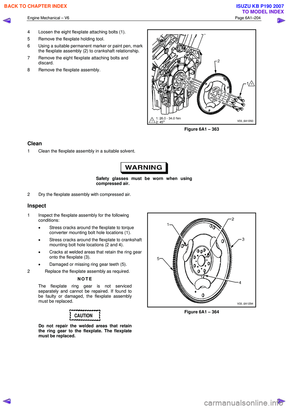
4 Loosen the eight flexplate attaching bolts (1).
5 Remove the flexplate holding tool.
6 Using a suitable permanent marker or paint pen, mark the flexplate assembly (2) to crankshaft relationship.
7 Remove the eight flexplate attaching bolts and discard.
8 Remove the flexplate assembly.
Figure 6A1 – 363
Clean
1 Clean the flexplate assembly in a suitable solvent.
Safety glasses must be worn when using
compressed air.
2 Dry the flexplate assembly with compressed air.
Inspect
1 Inspect the flexplate assembly for the following conditions:
• Stress cracks around the flexplate to torque
converter mounting bolt hole locations (1).
• Stress cracks around the flexplate to crankshaft
mounting bolt hole locations (2 and 4).
• Cracks at welded areas that retain the ring gear
onto the flexplate (3).
• Damaged or missing ring gear teeth (5).
2 Replace the flexplate assembly as required.
NOTE
The flexplate ring gear is not serviced
separately and cannot be repaired. If found to
be faulty or damaged, the flexplate assembly
must be replaced.
CAUTION
Do not repair the welded areas that retain
the ring gear to the flexplate. The flexplate
must be replaced.
Figure 6A1 – 364
BACK TO CHAPTER INDEX
TO MODEL INDEX
ISUZU KB P190 2007
Page 2786 of 6020
Engine Mechanical – V6 Page 6A1–9
Page 6A1–9
• Faulty operation or performance of any system or component being repaired,
• Damage to any system or components which depend on the proper operation of the system or component being
repaired,
• Faulty operation or performance of any systems or components which depend on the proper operation or
performance of the system or component under repair,
• Damage to fasteners, basic tool s or special tools and / or
• Leakage of coolant, lubricant or other vital fluids.
NOTE defined
A NOTE statement immediatel y precedes or follows an operating procedure, maintenance practice or condition that
requires highlighting. A NOTE statement also emphasises necessary characte ristics of a diagnostic or repair procedure.
A NOTE statement is designed to:
• Clarify a procedure,
• Present additional information for accomplishing a procedure,
• Give insight into the reasons for performi ng a procedure in the recommended manner, and / or
Present information that gives the tec hnician the benefit of past experience in accomplishing a procedure with greater
ease.
BACK TO CHAPTER INDEX
TO MODEL INDEX
ISUZU KB P190 2007
Page 2808 of 6020
Engine Mechanical – V6 Page 6A1–31
Page 6A1–31
2.2 Symptoms
Strategy Based Diagnosis
1 Review the system operations to familiarise yourself with the system functions, refer to 1 General Information and
6C1-1 Engine Management General Information.
2 Perform an engine management Diagnostic System Check, refer to Section 6C1-2 Engine Management – V6 –
Diagnostics .
All diagnosis on a vehicle should follow a logical process. Strategy based diagnosis is a uniform approach for repairing
all vehicle systems. The strategy based diagnostic flow chart may always be used to resolve a system problem. The
diagnostic flow chart is the place to start when repairs are required. For a detailed explanation of strategy based
diagnosis and the flow chart, refer to Section 6C1-2 Engine Management – V6 – Diagnostics .
Visual / Physical Inspection
1 Inspect the vehicle for aftermarket accessories which may adversely affect engine operation.
2 Inspect the easily accessible or visible system components for obvious signs of damage or conditions that may cause the symptom.
3 Check the engine lubrication system for the following:
• correct oil level,
• correct lubricant viscosity,
• correct oil filter application, and
• contaminated or burnt oil.
4 Confirm the exact operating conditions under whic h the fault occurs. Note factors such as:
• engine speed (r.p.m.),
• ambient temperature,
• engine temperature,
• engine warm-up time, and
• vehicle road speed.
5 Compare the engine sounds, if applic able, to a known good engine, and ensure you are not trying to diagnose a
normal operating condition.
Intermittent
For intermittent faults, test the vehicle under the same conditions the customer reported in order to confirm whether the
system is operating correctly.
BACK TO CHAPTER INDEX
TO MODEL INDEX
ISUZU KB P190 2007
Page 2809 of 6020
Engine Mechanical – V6 Page 6A1–32
Page 6A1–32
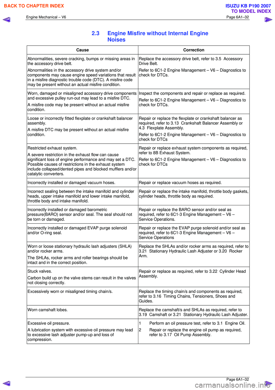
2.3 Engine Misfire without Internal Engine
Noises
Cause Correction
Abnormalities, severe cracking, bumps or missing areas in
the accessory drive belt.
Abnormalities in the accessory drive system and/or
components may cause engine speed variations that result
in a misfire diagnostic trouble code (DTC). A misfire code
may be present without an ac tual misfire condition. Replace the accessory drive belt, refer to 3.5 Accessory
Drive Belt.
Refer to 6C1-2 Engine Management – V6 – Diagnostics to
check for DTCs.
Worn, damaged or misaligned accessory drive components
and excessive pulley run-out may lead to a misfire DTC.
A misfire code may be present without an actual misfire
condition. Inspect the components and repair or replace as required.
Refer to 6C1-2 Engine Management – V6 – Diagnostics to
check for DTCs.
Loose or incorrectly fitted flexplate or crankshaft balancer
assembly.
A misfire DTC may be present without an actual misfire
condition. Repair or replace the flexplat
e or crankshaft balancer as
required, refer to 3.13 Crankshaft Balancer Assembly or
4.3 Flexplate Assembly.
Refer to 6C1-2 Engine Management – V6 – Diagnostics to
check for DTCs
Restricted exhaust system.
A severe restriction in the exhaust flow can cause
significant loss of engine performance and may set a DTC.
Possible causes of restrict ions in the exhaust system
include collapsed/dented pipes and blocked mufflers and/or
catalytic converters. Repair or replace exhaust syst
em components as required,
refer to 8B Exhaust System.
Refer to 6C1-2 Engine Management – V6 – Diagnostics to
check for DTCs
Incorrectly installed or damaged vacuum hoses. Repair or replace vacuum hoses as required.
Incorrect sealing between the intake manifold and cylinder
heads, upper intake manifold and lower intake manifold,
throttle body and intake manifold. Repair or replace the intake
manifold, throttle body gaskets,
cylinder heads, throttle body as required.
Incorrectly installed or damaged barometric
pressure(BARO) sensor and/or seal. The seal should not
be torn or damaged. Repair or replace the BARO sensor and/or seal as
required, refer to 6C1-3 Engine Management – V6 –
Service Operations.
Incorrectly installed or damaged EVAP purge solenoid
and/or O-ring seal. Repair or replace the EVAP purge solenoid and/or seal as
required, refer to 6C1-3 Engine Management – V6 –
Service Operations
Worn or loose stationary hydraulic lash adjusters (SHLA)
and/or rocker arms.
The SHLAs, rocker arms and roller bearings should be
intact and in the correct position. Replace the SHLAs and/or rocker arms as required, refer to
3.21 Stationary Hydraulic Las h Adjuster or 3.20 Rocker
Arm.
Stuck valves.
Carbon build up on the valve stem s can result in the valves
not closing correctly. Repair or replace as required, refer to 3.22 Cylinder Head
Assembly.
Excessively worn or misaligned timing chain/s. Replace the timing chain/s and components as required,
refer to 3.16 Timing Chains, Tensioners, Shoes and
Guides.
Worn camshaft lobes. Replace the camshaft/s and SHLAs as required, refer to
3.19 Camshaft or 3.21 Stati onary Hydraulic Lash Adjuster.
Excessive oil pressure.
A lubrication system with ex cessive oil pressure may lead
to excessive lash adjuster pump-up and loss of
compression. 1 Perform an oil pressure tes
t, refer to 3.1 Engine Oil.
2 Repair or replace the engine oil pump as required, refer to 3.17 Oil Pump Assembly.
BACK TO CHAPTER INDEX
TO MODEL INDEX
ISUZU KB P190 2007
Page 2811 of 6020
Engine Mechanical – V6 Page 6A1–34
Page 6A1–34
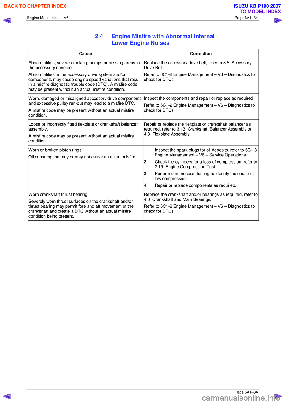
2.4 Engine Misfire with Abnormal Internal
Lower Engine Noises
Cause Correction
Abnormalities, severe cracking, bumps or missing areas in
the accessory drive belt.
Abnormalities in the accessory drive system and/or
components may cause engine speed variations that result
in a misfire diagnostic trouble code (DTC). A misfire code
may be present without an ac tual misfire condition. Replace the accessory drive belt, refer to 3.5 Accessory
Drive Belt.
Refer to 6C1-2 Engine Management – V6 – Diagnostics to
check for DTCs
Worn, damaged or misaligned accessory drive components
and excessive pulley run-out may lead to a misfire DTC.
A misfire code may be present without an actual misfire
condition. Inspect the components and repair or replace as required.
Refer to 6C1-2 Engine Management – V6 – Diagnostics to
check for DTCs
Loose or Incorrectly fitted flexplate or crankshaft balancer
assembly.
A misfire code may be present without an actual misfire
condition. Repair or replace the flexplat
e or crankshaft balancer as
required, refer to 3.13 Crankshaft Balancer Assembly or
4.3 Flexplate Assembly.
Worn or broken piston rings.
Oil consumption may or may not cause an actual misfire. 1 Inspect the spark plugs for oil deposits, refer to 6C1-3
Engine Management – V6 – Service Operations.
2 Check the cylinders for a loss of compression, refer to 2.15 Engine Compression Test.
3 Perform compression testing to identify the cause of
low compression.
4 Repair or replace components as required.
Worn crankshaft thrust bearing.
Severely worn thrust surfaces on the crankshaft and/or
thrust bearing may permit fore and aft movement of the
crankshaft and create a DTC wi thout an actual misfire
condition being present. Replace the crankshaft and/or bear
ings as required, refer to
4.6 Crankshaft and Main Bearings.
Refer to 6C1-2 Engine Management – V6 – Diagnostics to
check for DTCs
BACK TO CHAPTER INDEX
TO MODEL INDEX
ISUZU KB P190 2007
Page 2820 of 6020
Engine Mechanical – V6 Page 6A1–43
Page 6A1–43
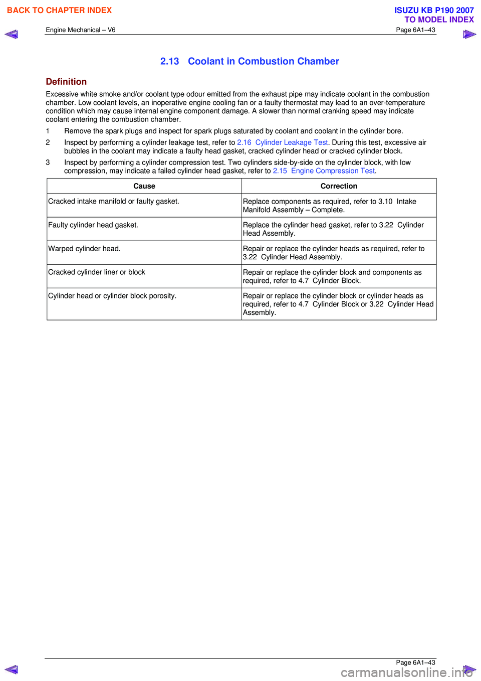
2.13 Coolant in Combustion Chamber
Definition
Excessive white smoke and/or coolant type odour emitted from the exhaust pipe may indicate coolant in the combustion
chamber. Low coolant levels, an inoperativ e engine cooling fan or a faulty thermostat may lead to an over-temperature
condition which may cause internal engine component damage. A slower than normal cranking speed may indicate
coolant entering the combustion chamber.
1 Remove the spark plugs and inspect for spark plugs sa turated by coolant and coolant in the cylinder bore.
2 Inspect by performing a cylinder leakage test, refer to 2.16 Cylinder Leakage Test. During this test, excessive air
bubbles in the coolant may indicate a faulty head ga sket, cracked cylinder head or cracked cylinder block.
3 Inspect by performing a cylinder compression test. Two cylinders side-by-side on the cylinder block, with low
compression, may indicate a fa iled cylinder head gasket, refer to 2.15 Engine Compression Test.
Cause Correction
Cracked intake manifold or faulty gasket. Replace components as required, refer to 3.10 Intake
Manifold Assembly – Complete.
Faulty cylinder head gasket. Replace the cylinder head gasket, refer to 3.22 Cylinder
Head Assembly.
Warped cylinder head. Repair or replace the cylinder heads as required, refer to
3.22 Cylinder Head Assembly.
Cracked cylinder liner or block Repair or replace the cylinder block and components as
required, refer to 4.7 Cylinder Block.
Cylinder head or cylinder block porosity. Repair or replace the cylinder block or cylinder heads as
required, refer to 4.7 Cylinder Block or 3.22 Cylinder Head
Assembly.
BACK TO CHAPTER INDEX
TO MODEL INDEX
ISUZU KB P190 2007
Page 2821 of 6020
Engine Mechanical – V6 Page 6A1–44
Page 6A1–44
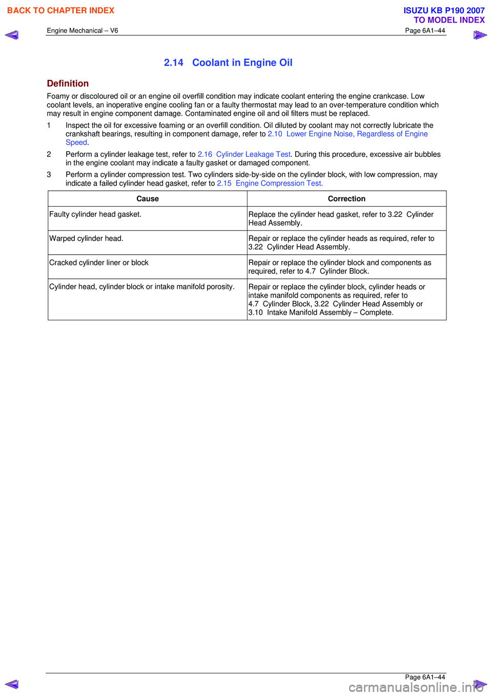
2.14 Coolant in Engine Oil
Definition
Foamy or discoloured oil or an engine oil overfill condition may indicate coolant entering the engine crankcase. Low
coolant levels, an inoperative engine cooli ng fan or a faulty thermostat may lead to an over-temperature condition which
may result in engine component damage. Contaminat ed engine oil and oil filters must be replaced.
1 Inspect the oil for excessive foaming or an overfill condition. Oil diluted by coolant may not correctly lubricate the
crankshaft bearings, resulting in component damage, refer to 2.10 Lower Engine Noise, Regardless of Engine
Speed .
2 Perform a cylinder leakage test, refer to 2.16 Cylinder Leakage Test. During this procedure, excessive air bubbles
in the engine coolant may indicate a faulty gasket or damaged component.
3 Perform a cylinder compression test. Two cylinders side-by -side on the cylinder block, with low compression, may
indicate a failed cylinder head gasket, refer to 2.15 Engine Compression Test.
Cause Correction
Faulty cylinder head gasket. Replace the cylinder head gasket, refer to 3.22 Cylinder
Head Assembly.
Warped cylinder head. Repair or replace the cylinder heads as required, refer to
3.22 Cylinder Head Assembly.
Cracked cylinder liner or block Repair or replace the cylinder block and components as
required, refer to 4.7 Cylinder Block.
Cylinder head, cylinder block or intake manifold porosity. Repair or replace the cylinder block, cylinder heads or
intake manifold components as required, refer to
4.7 Cylinder Block, 3.22 Cylinder Head Assembly or
3.10 Intake Manifold Assembly – Complete.
BACK TO CHAPTER INDEX
TO MODEL INDEX
ISUZU KB P190 2007