2007 ISUZU KB P190 air condition
[x] Cancel search: air conditionPage 2524 of 6020
Engine Mechanical – V6 Page 6A1–45
Step Action Yes No
10 Inspect for missing, loose or incorrect fasteners.
Did you find any missing, loose or incorrect fasteners? Go to Step 11 Go to Step 12
11 Tighten any loose fasteners to the torque specification as provided in
provided in 6. Torque W rench Specifications.
Replace any incorrect or missing fasteners.
Did you complete the repairs? Go to Step 15 —
12 Inspect for a bent pulley. Did you find any bent pulleys? Go to Step 13 Go to Step 14
13 Replace bent pulleys as required. Did you complete the repair? Go to Step 15 —
14 Replace the accessory drive belt, refer to 3.5 Accessory Drive Belt.
Did you complete the repair? Go to Step 15 —
15 Reinstall the accessory drive belt and operate the system to confirm the repair.
Did you correct the chirp noise? Accessory drive
system OK Go to 2.2
Symptoms, and restart the
diagnosis
Drive Belt Squeal
Definition
Accessory drive belt squealing can be defined as a loud screeching noise caused by a slipping drive belt. Belt squeal is
unusual in multi-rib belts. Drive belt squeal generally occurs when a heavy load is applied to the drive belt, such as an
air-conditioning compressor engagement, snapping the throttle, seized pulley or a faulty accessory drive component.
Diagnostic Aids
If the noise is intermittent, confirm the accessory drive components by varying their loads, making sure they are operated
to their maximum capacity. An overcharged A/C system, restrictions in the power steering pressure circuit or a faulty
generator or coolant pump are likely causes of accessory drive belt squeal.
A loose or incorrectly installed body component, suspension component or other item may be the cause of the noise.
Test Description
The numbers below refer to steps in the diagnostic table.
2 The noise may not be engine related. This step is to confirm the engine is making the noise. If the engine is not making the noise, do not proceed further with this diagnostic procedure.
3 The noise may be an internal engine noise. Removing the drive belt and operating the engine briefly will confirm whether or not the noise is related to the drive belt.
CAUTION
When running the engine with the accessory
drive belt removed, the coolant pump will not
be operating and the engine may overheat if
left unsupervised even for a short period.
NOTE
There may also be a number of DTCs set when
running the engine with the accessory drive belt
removed.
4 Confirms an accessory drive component does not have a seized bearing. W ith the belt removed, test the bearings in the accessory drive components spin free and smooth.
5 Confirms the drive belt tensioner is operating correctly. If the drive belt tensioner is not operating correctly, drive belt tension will not be maintained, resulting in a belt squealing noise
6 Confirms the belt is not too long, which would prevent the tensioner from working as intended. Also, if an excessively long belt has been fitted, it may also be routed incorrectly and may be turning an accessory drive
component in the wrong direction.
BACK TO CHAPTER INDEX
TO MODEL INDEX
ISUZU KB P190 2007
Page 2529 of 6020

Engine Mechanical – V6 Page 6A1–50
Diagnostic Table
Step Action Yes No
1 Did you review the information provided in 2.2 Symptoms, and
perform the required inspections. Go to Step 2 Go to 2.2
Symptoms
2 Confirm the customer complaint. Is there a rumbling noise? Go to Step 3 Refer to Diagnostic
Aids in this Section
3 1 Remove the drive belt, refer to 3.5 Accessory Drive Belt.
2 Operate the engine for no more than 40 seconds.
Does the vibration noise still exist? Accessory drive
system OK.
Go to 4.2
Symptoms, and
restart the diagnosis Go to Step 4
4 Inspect the accessory drive belt for damage, wear, debris build-up or
sections of missing ribs.
Did you find any damage, wear, debris build-up or missing ribs? Go to Step 5 Go to Step 6
5 Install a new accessory drive belt, refer to 3.5 Accessory Drive Belt.
Did you replace the accessory drive belt? Go to Step 10 —
6 Inspect for incorrect, loose, missing or damaged fasteners. Did you find any incorrect, loose, missing or damaged fasteners? Go to Step 7 Go to Step 8
7 Tighten any loose fasteners to the correct torque specification, refer to
6 Torque W rench Specifications.
Replace any incorrect or missing fasteners.
Did you complete the repairs? Go to Step 10 —
8 Inspect the coolant pump for a bent shaft, refer to 6B1 Engine Cooling – V6.
Did you find and repair a bent coolant pump shaft? Go to Step 10 Go to Step 9
9 Inspect for bent, cracked or damaged accessory drive component mounting brackets.
Did you find and repair any bent brackets? Go to Step 10 Refer to Diagnostic
Aids in this Section
10 If required, reinstall the accessory drive belt and operate the system to
confirm the repair.
Did you correct the vibration? Accessory drive
system OK Refer to Diagnostic
Aids in this Section
Drive Belt Falls Off
Definition
The drive belt falls off during normal operation or does not ride correctly on the accessory drive pulleys.
Diagnostic Aids
If the accessory drive belt repeatedly falls off the drive pulleys, this is most likely due to pulley misalignment.
An extra load that is quickly applied and released by an accessory drive component (e.g. A/C compressor) may cause
the accessory drive belt to fall off. In this circumstance, confirm the fault by operating the accessory drive components in
turn, noting which one caused the belt to fall off.
Lack of drive belt tension may also cause the belt to fall off the pulleys. Low drive belt tension could be caused by one of
the following:
• an incorrect drive belt length,
• a faulty drive belt tensioner, or
• a stretched or faulty drive belt.
Test Description
The numbers below refer to steps in the diagnostic table.
2 Confirms the condition of the drive belt. Damage may have occurred to the drive belt when it first fell off or it may have been damaged which caused the belt to fall off.
4 Misalignment of the pulleys may be caused by:
BACK TO CHAPTER INDEX
TO MODEL INDEX
ISUZU KB P190 2007
Page 2545 of 6020
Engine Mechanical – V6 Page 6A1–66
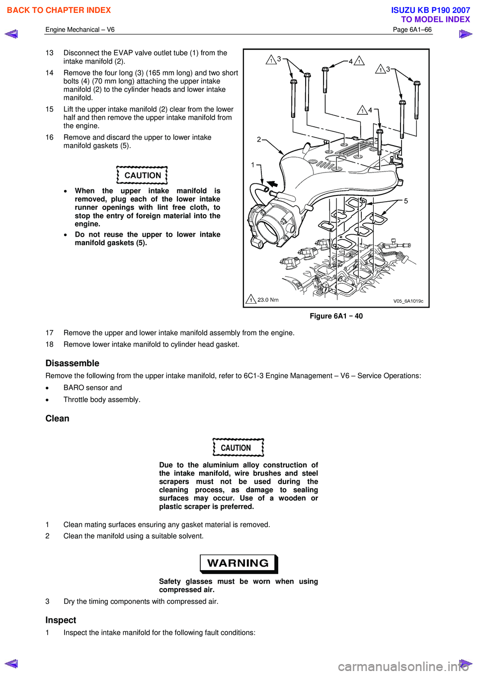
13 Disconnect the EVAP valve outlet tube (1) from the
intake manifold (2).
14 Remove the four long (3) (165 mm long) and two short bolts (4) (70 mm long) attaching the upper intake
manifold (2) to the cylinder heads and lower intake
manifold.
15 Lift the upper intake manifold (2) clear from the lower half and then remove the upper intake manifold from
the engine.
16 Remove and discard the upper to lower intake manifold gaskets (5).
• When the upper intake manifold is
removed, plug each of the lower intake
runner openings with lint free cloth, to
stop the entry of foreign material into the
engine.
• Do not reuse the upper to lower intake
manifold gaskets (5).
Figure 6A1 –
––
–
40
17 Remove the upper and lower intake manifold assembly from the engine.
18 Remove lower intake manifold to cylinder head gasket.
Disassemble
Remove the following from the upper intake manifold, refer to 6C1-3 Engine Management – V6 – Service Operations:
• BARO sensor and
• Throttle body assembly.
Clean
CAUTION
Due to the aluminium alloy construction of
the intake manifold, wire brushes and steel
scrapers must not be used during the
cleaning process, as damage to sealing
surfaces may occur. Use of a wooden or
plastic scraper is preferred.
1 Clean mating surfaces ensuring any gasket material is removed.
2 Clean the manifold using a suitable solvent.
Safety glasses must be worn when using
compressed air.
3 Dry the timing components with compressed air.
Inspect
1 Inspect the intake manifold for the following fault conditions:
BACK TO CHAPTER INDEX
TO MODEL INDEX
ISUZU KB P190 2007
Page 2552 of 6020
Engine Mechanical – V6 Page 6A1–73
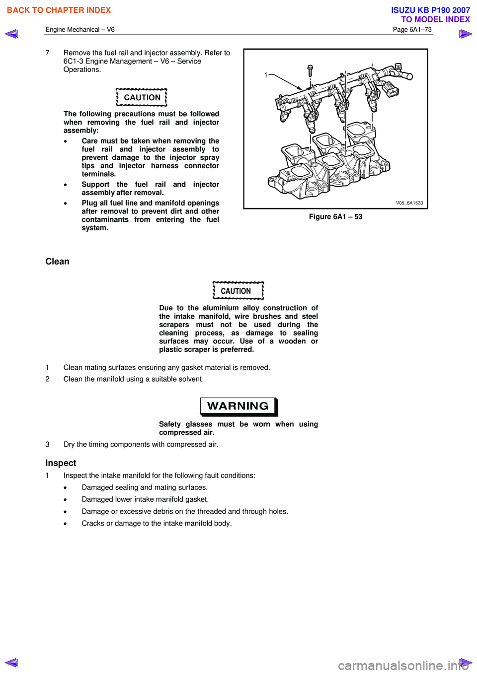
7 Remove the fuel rail and injector assembly. Refer to
6C1-3 Engine Management – V6 – Service
Operations.
The following precautions must be followed
when removing the fuel rail and injector
assembly:
• Care must be taken when removing the
fuel rail and injector assembly to
prevent damage to the injector spray
tips and injector harness connector
terminals.
• Support the fuel rail and injector
assembly after removal.
• Plug all fuel line and manifold openings
after removal to prevent dirt and other
contaminants from entering the fuel
system.
Figure 6A1 – 53
Clean
CAUTION
Due to the aluminium alloy construction of
the intake manifold, wire brushes and steel
scrapers must not be used during the
cleaning process, as damage to sealing
surfaces may occur. Use of a wooden or
plastic scraper is preferred.
1 Clean mating surfaces ensuring any gasket material is removed.
2 Clean the manifold using a suitable solvent
Safety glasses must be worn when using
compressed air.
3 Dry the timing components with compressed air.
Inspect
1 Inspect the intake manifold for the following fault conditions:
• Damaged sealing and mating surfaces.
• Damaged lower intake manifold gasket.
• Damage or excessive debris on the threaded and through holes.
• Cracks or damage to the intake manifold body.
BACK TO CHAPTER INDEX
TO MODEL INDEX
ISUZU KB P190 2007
Page 2564 of 6020
Engine Mechanical – V6 Page 6A1–85
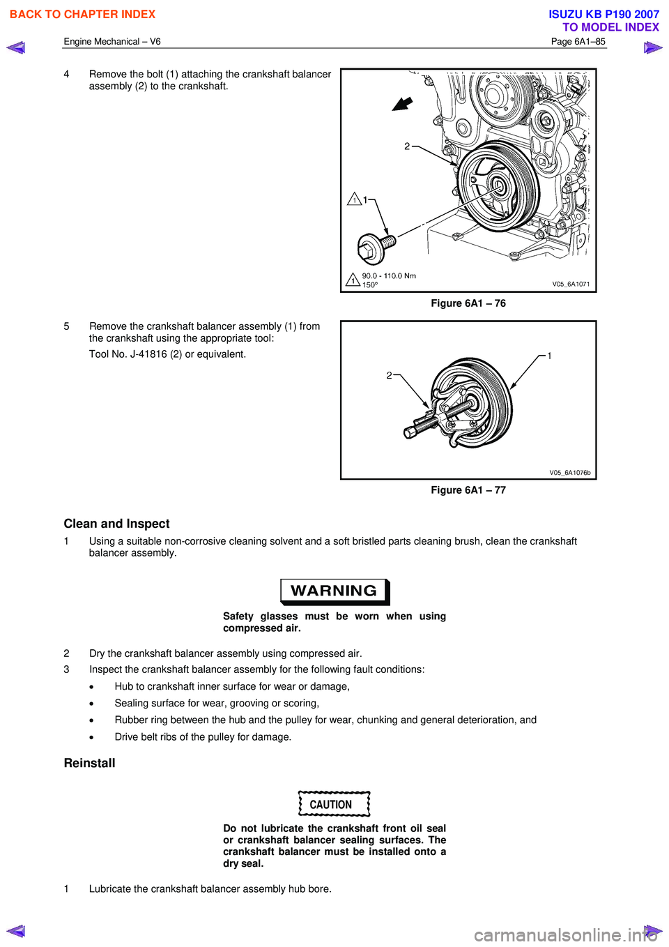
4 Remove the bolt (1) attaching the crankshaft balancer
assembly (2) to the crankshaft.
Figure 6A1 – 76
5 Remove the crankshaft balancer assembly (1) from the crankshaft using the appropriate tool:
Tool No. J-41816 (2) or equivalent.
Figure 6A1 – 77
Clean and Inspect
1 Using a suitable non-corrosive cleaning solvent and a soft bristled parts cleaning brush, clean the crankshaft balancer assembly.
Safety glasses must be worn when using
compressed air.
2 Dry the crankshaft balancer assembly using compressed air.
3 Inspect the crankshaft balancer assembly for the following fault conditions:
• Hub to crankshaft inner surface for wear or damage,
• Sealing surface for wear, grooving or scoring,
• Rubber ring between the hub and the pulley for wear, chunking and general deterioration, and
• Drive belt ribs of the pulley for damage.
Reinstall
CAUTION
Do not lubricate the crankshaft front oil seal
or crankshaft balancer sealing surfaces. The
crankshaft balancer must be installed onto a
dry seal.
1 Lubricate the crankshaft balancer assembly hub bore.
BACK TO CHAPTER INDEX
TO MODEL INDEX
ISUZU KB P190 2007
Page 2570 of 6020

Engine Mechanical – V6 Page 6A1–91
Inspect
1 Inspect both sides of the engine front cover for the
following conditions:
• damage to the camshaft position actuator valve
oil seal bores (1),
• damage to the bolt holes (2),
• damage and/or corrosion to the engine coolant
passage (3),
• dents or damage to the exterior (4),
• damage to the crankshaft front oil seal bore (5),
• gouges or damage to the coolant pump sealing
surfaces (6), and
• damage to the coolant pump bolt hole
threads (7).
2 Repair or replace the front cover as required.
Figure 6A1 – 90
Reassemble
1 Install a new crankshaft front oil seal (1) into the front cover (2) using crankshaft front seal installer, Tool
No. J-29184 (3) and a suitable hammer.
CAUTION
Do not lubricate the crankshaft front oil seal
or crankshaft balancer sealing surfaces. The
crankshaft balancer is installed into a dry
seal.
Figure 6A1 – 91
2 Install a new camshaft position actuator valve oil seal (1) into the front cover (2) using Tool No. EN-46103
(3) and a suitable hammer.
Figure 6A1 – 92
BACK TO CHAPTER INDEX
TO MODEL INDEX
ISUZU KB P190 2007
Page 2629 of 6020
Engine Mechanical – V6 Page 6A1–150
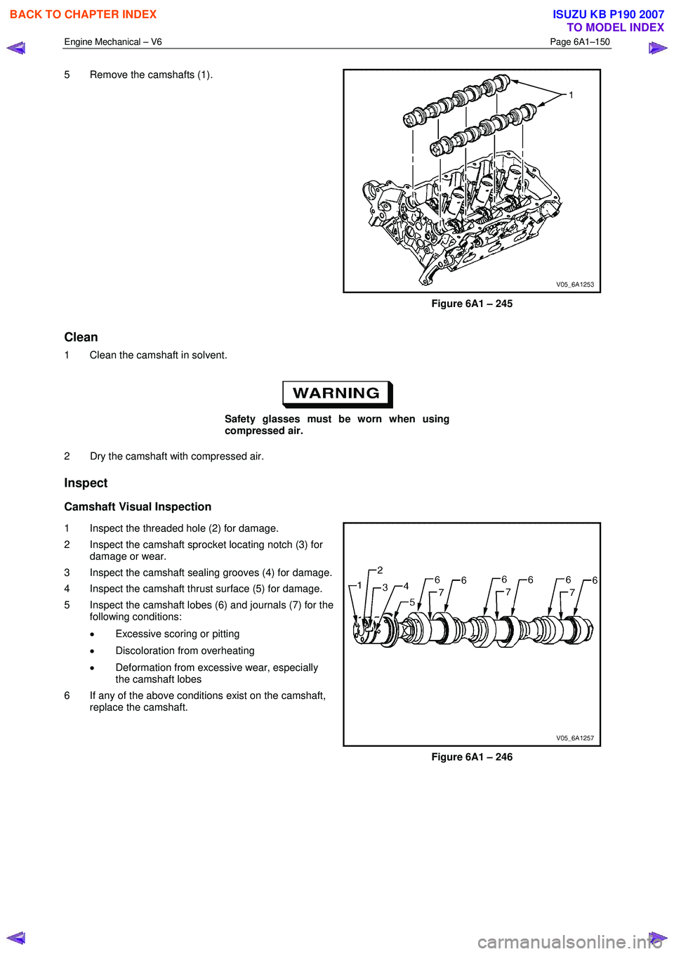
5 Remove the camshafts (1).
Figure 6A1 – 245
Clean
1 Clean the camshaft in solvent.
Safety glasses must be worn when using
compressed air.
2 Dry the camshaft with compressed air.
Inspect
Camshaft Visual Inspection
1 Inspect the threaded hole (2) for damage.
2 Inspect the camshaft sprocket locating notch (3) for damage or wear.
3 Inspect the camshaft sealing grooves (4) for damage.
4 Inspect the camshaft thrust surface (5) for damage.
5 Inspect the camshaft lobes (6) and journals (7) for the following conditions:
• Excessive scoring or pitting
• Discoloration from overheating
• Deformation from excessive wear, especially
the camshaft lobes
6 If any of the above conditions exist on the camshaft, replace the camshaft.
Figure 6A1 – 246
BACK TO CHAPTER INDEX
TO MODEL INDEX
ISUZU KB P190 2007
Page 2652 of 6020
Engine Mechanical – V6 Page 6A1–173
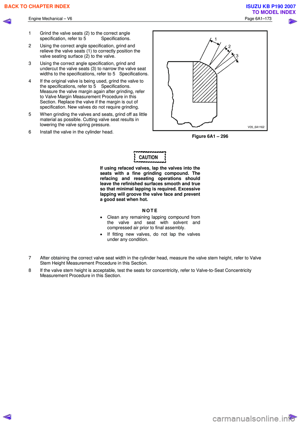
1 Grind the valve seats (2) to the correct angle
specification, refer to 5 Specifications.
2 Using the correct angle specification, grind and relieve the valve seats (1) to correctly position the
valve seating surface (2) to the valve.
3 Using the correct angle specification, grind and undercut the valve seats (3) to narrow the valve seat
widths to the specifications, refer to 5 Specifications.
4 If the original valve is being used, grind the valve to the specifications, refer to 5 Specifications.
Measure the valve margin again after grinding, refer
to Valve Margin Measurement Procedure in this
Section. Replace the valve if the margin is out of
specification. New valves do not require grinding.
5 W hen grinding the valves and seats, grind off as little material as possible. Cutting valve seat results in
lowering the valve spring pressure.
6 Install the valve in the cylinder head.
Figure 6A1 – 296
CAUTION
If using refaced valves, lap the valves into the
seats with a fine grinding compound. The
refacing and reseating operations should
leave the refinished surfaces smooth and true
so that minimal lapping is required. Excessive
lapping will groove the valve face and prevent
a good seat when hot.
NOTE
• Clean any remaining lapping compound from
the valve and seat with solvent and
compressed air prior to final assembly.
• If fitting new valves, do not lap the valves
under any condition.
7 After obtaining the correct valve seat width in the cylinder head, measure the valve stem height, refer to Valve Stem Height Measurement Procedure in this Section.
8 If the valve stem height is acceptable, test the seats for concentricity, refer to Valve-to-Seat Concentricity Measurement Procedure in this Section.
BACK TO CHAPTER INDEX
TO MODEL INDEX
ISUZU KB P190 2007