2007 ISUZU KB P190 air condition
[x] Cancel search: air conditionPage 2999 of 6020
Engine Mechanical – V6 Page 6A1–222
Page 6A1–222
Clean
CAUTION
Due to the aluminium alloy construction of
the cylinder head, wire brushes and steel
scrapers must not be used during the
cleaning process, as damage to sealing
surfaces may occur. Use a wood or plastic
scraper as an alternative.
1 Remove any old thread sealant, gasket material or seal ant using commercially available plastic or wooden scraper.
2 Clean all cylinder head surfaces with non-corrosive solvent.
Safety glasses must be worn when using
compressed air.
3 Blow out all the oil galleries using compressed air.
4 Remove any carbon deposits fr om the combustion chambers.
5 Clean any debris or build-up from the lifter pockets.
Inspect
Visual Inspection
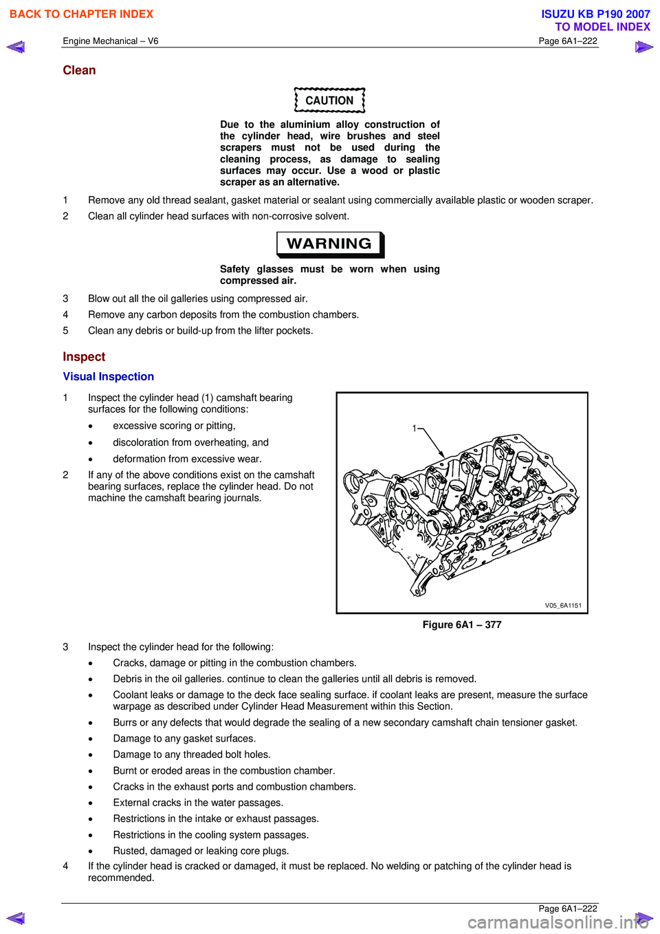
1 Inspect the cylinder head (1) camshaft bearing surfaces for the following conditions:
• excessive scoring or pitting,
• discoloration from overheating, and
• deformation from excessive wear.
2 If any of the above conditions exist on the camshaft bearing surfaces, replace the cylinder head. Do not
machine the camshaft bearing journals.
Figure 6A1 – 377
3 Inspect the cylinder head for the following: • Cracks, damage or pitting in the combustion chambers.
• Debris in the oil galleries. continue to cl ean the galleries until all debris is removed.
• Coolant leaks or damage to the deck face sealing surfac e. if coolant leaks are present, measure the surface
warpage as described under Cylinder Head M easurement within this Section.
• Burrs or any defects that would degrade the sealing of a new secondar y camshaft chain tensioner gasket.
• Damage to any gasket surfaces.
• Damage to any threaded bolt holes.
• Burnt or eroded areas in the combustion chamber.
• Cracks in the exhaust ports and combustion chambers.
• External cracks in the water passages.
• Restrictions in the intake or exhaust passages.
• Restrictions in the cooling system passages.
• Rusted, damaged or leaking core plugs.
4 If the cylinder head is cracked or damaged, it must be r eplaced. No welding or patching of the cylinder head is
recommended.
BACK TO CHAPTER INDEX
TO MODEL INDEX
ISUZU KB P190 2007
Page 3006 of 6020
Engine Mechanical – V6 Page 6A1–229
Page 6A1–229
NOTE
• Clean any remaining lapping compound from
the valve and seat with solvent and
compressed air prior to final assembly.
• If fitting new valves, do not lap the valves
under any condition.
7 After obtaining the correct valve seat width in the cylinder head, measure the valve stem height, refer to Valve
Stem Height Measurement Pr ocedure in this Section.
8 If the valve stem height is acceptabl e, test the seats for concentricity, refer to Valve-to-Seat Concentricity
Measurement Procedure in this Section.
Valve Stem Height Measurement Procedure
CAUTION
To determine the valve stem height
measurement, measure from the valve
spring seat to the valve spring retainer.
1 Install the valve into the valve guide.
2 Ensure the valve is seated to the valve seat.
3 Install the valve stem oil seal.
4 Install the valve spring retainer and valve stem keys.
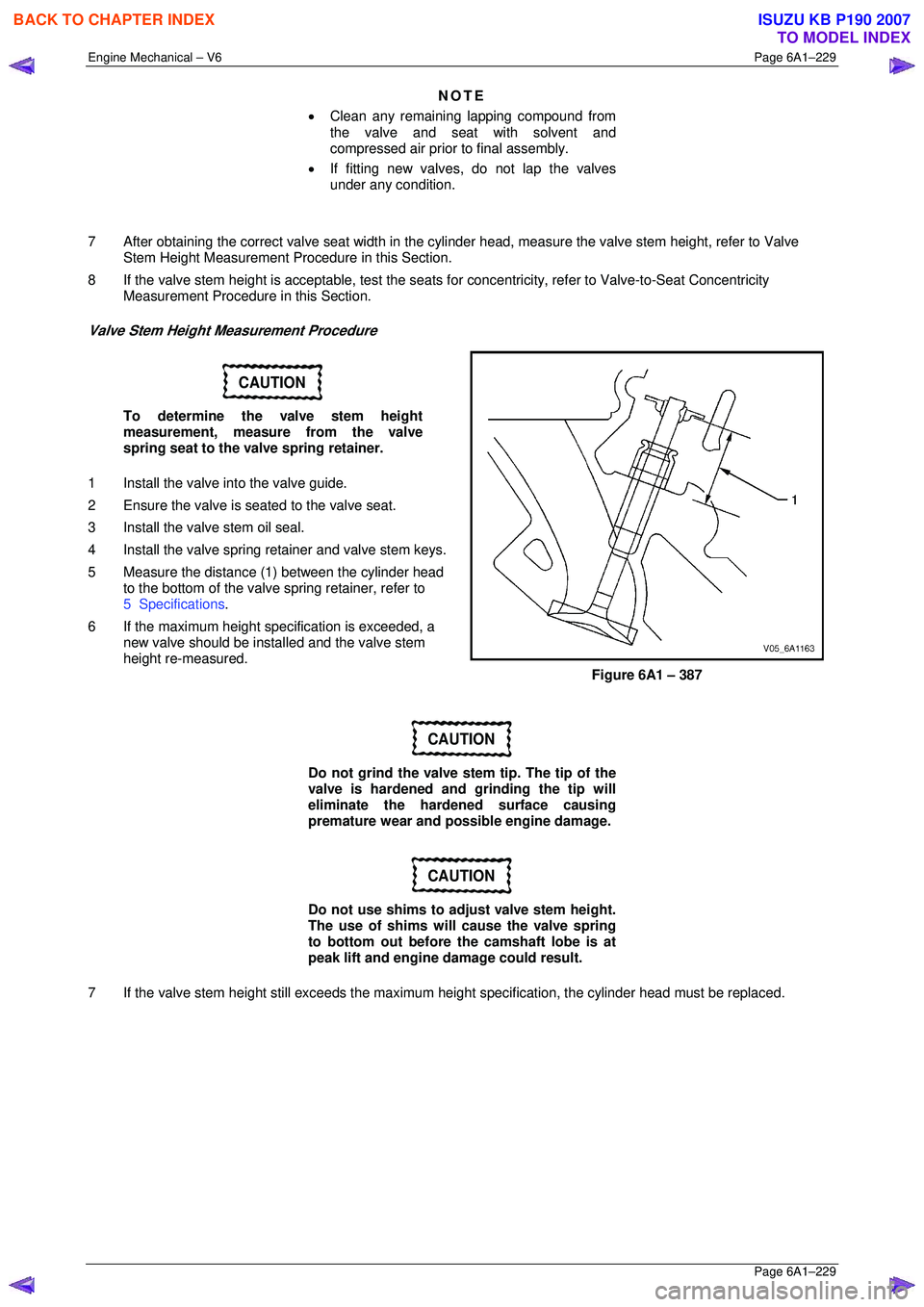
5 Measure the distance (1 ) between the cylinder head
to the bottom of the valve spring retainer, refer to
5 Specifications .
6 If the maximum height spec ification is exceeded, a
new valve should be installed and the valve stem
height re-measured.
Figure 6A1 – 387
CAUTION
Do not grind the valve stem tip. The tip of the
valve is hardened and grinding the tip will
eliminate the hardened surface causing
premature wear and possible engine damage.
CAUTION
Do not use shims to adjust valve stem height.
The use of shims will cause the valve spring
to bottom out before the camshaft lobe is at
peak lift and engine damage could result.
7 If the valve stem height still exceeds the maximum height specification, the cylinder head must be replaced.
BACK TO CHAPTER INDEX
TO MODEL INDEX
ISUZU KB P190 2007
Page 3033 of 6020
Engine Mechanical – V6 Page 6A1–256
Page 6A1–256
Inspect
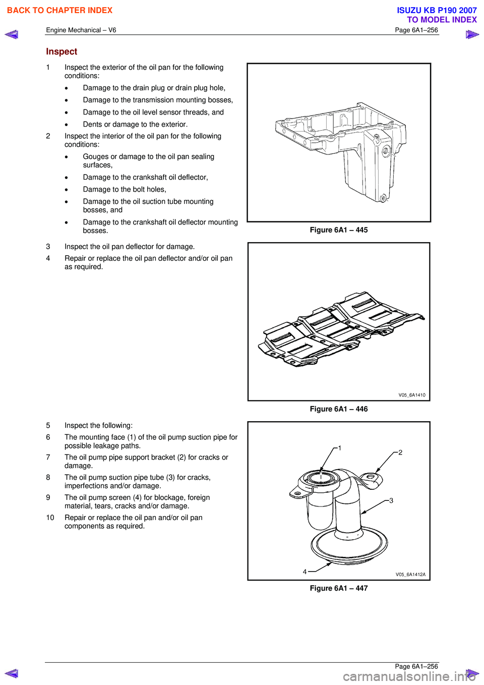
1 Inspect the exterior of the oil pan for the following
conditions:
• Damage to the drain plug or drain plug hole,
• Damage to the transmission mounting bosses,
• Damage to the oil level sensor threads, and
• Dents or damage to the exterior.
2 Inspect the interior of the oil pan for the following conditions:
• Gouges or damage to the oil pan sealing
surfaces,
• Damage to the crankshaft oil deflector,
• Damage to the bolt holes,
• Damage to the oil suction tube mounting
bosses, and
• Damage to the crankshaft oil deflector mounting
bosses.
Figure 6A1 – 445
3 Inspect the oil pan deflector for damage.
4 Repair or replace the o il pan deflector and/or oil pan
as required.
Figure 6A1 – 446
5 Inspect the following:
6 The mounting face (1) of the oil pump suction pipe for possible leakage paths.
7 The oil pump pipe support bracket (2) for cracks or damage.
8 The oil pump suction pipe tube (3) for cracks, imperfections and/or damage.
9 The oil pump screen (4) for blockage, foreign material, tears, cracks and/or damage.
10 Repair or replace the oil pan and/or oil pan components as required.
Figure 6A1 – 447
BACK TO CHAPTER INDEX
TO MODEL INDEX
ISUZU KB P190 2007
Page 3037 of 6020
Engine Mechanical – V6 Page 6A1–260
Page 6A1–260
Inspect
1 Inspect the flexplate assembly for the following
conditions:
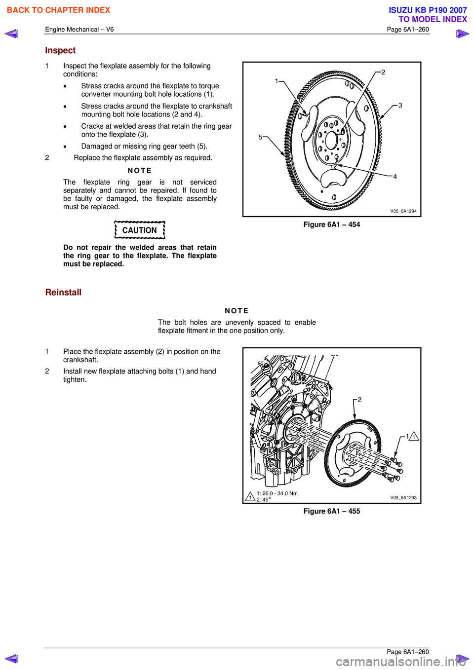
• Stress cracks around the flexplate to torque
converter mounting bolt hole locations (1).
• Stress cracks around the flexplate to crankshaft
mounting bolt hole locations (2 and 4).
• Cracks at welded areas that retain the ring gear
onto the flexplate (3).
• Damaged or missing ring gear teeth (5).
2 Replace the flexplate assembly as required.
NOTE
The flexplate ring gear is not serviced
separately and cannot be repaired. If found to
be faulty or damaged, the flexplate assembly
must be replaced.
CAUTION
Do not repair the welded areas that retain
the ring gear to the fl explate. The flexplate
must be replaced.
Figure 6A1 – 454
Reinstall
NOTE
The bolt holes are unevenly spaced to enable
flexplate fitment in the one position only.
1 Place the flexplate assembly (2) in position on the crankshaft.
2 Install new flexplate attaching bolts (1) and hand tighten.
Figure 6A1 – 455
BACK TO CHAPTER INDEX
TO MODEL INDEX
ISUZU KB P190 2007
Page 3046 of 6020
Engine Mechanical – V6 Page 6A1–269
Page 6A1–269
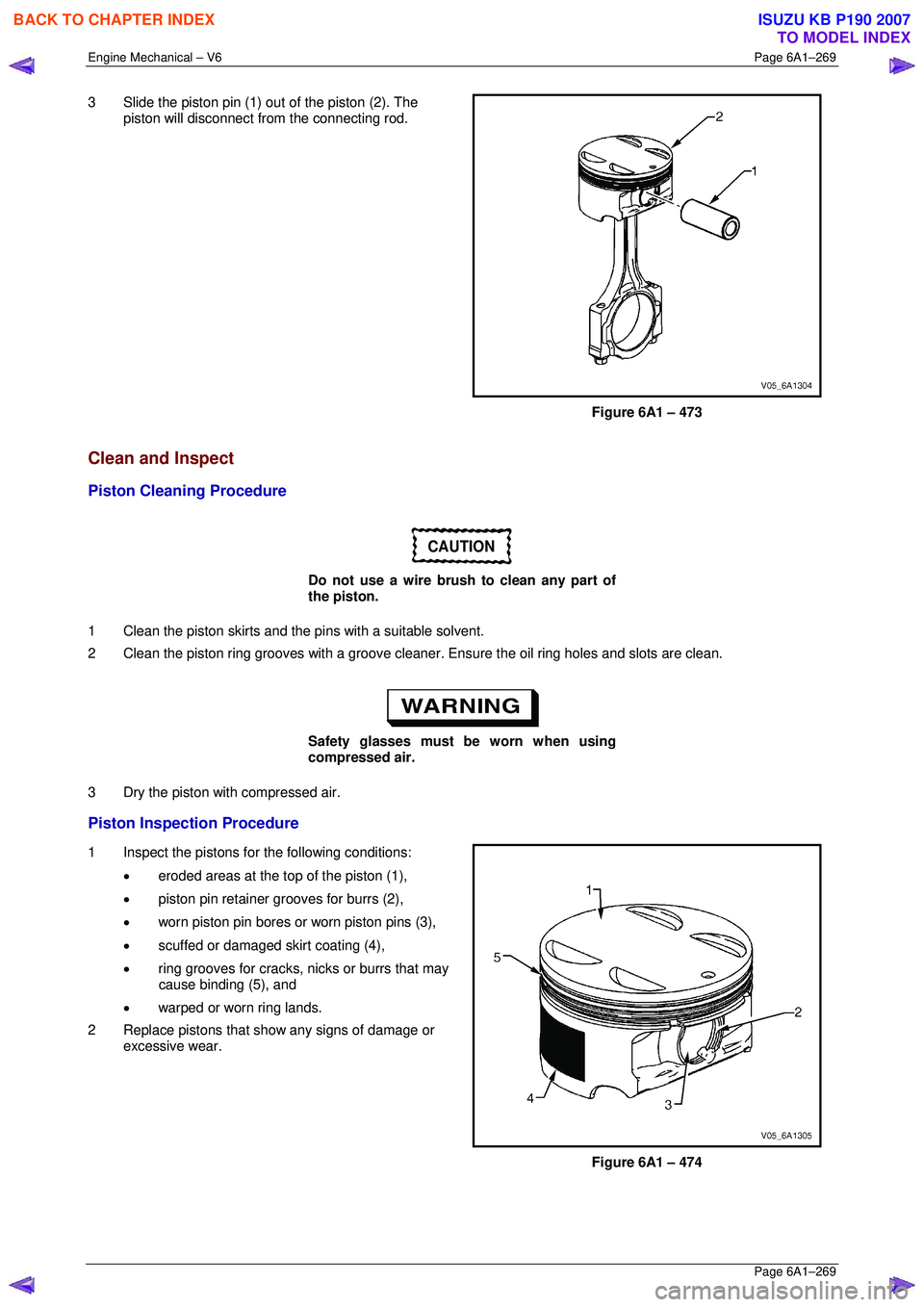
3 Slide the piston pin (1) out of the piston (2). The
piston will disconnect from the connecting rod.
Figure 6A1 – 473
Clean and Inspect
Piston Cleaning Procedure
CAUTION
Do not use a wire brush to clean any part of
the piston.
1 Clean the piston skirts and the pi ns with a suitable solvent.
2 Clean the piston ring grooves with a groove cleaner . Ensure the oil ring holes and slots are clean.
Safety glasses must be worn when using
compressed air.
3 Dry the piston with compressed air.
Piston Inspection Procedure
1 Inspect the pistons for the following conditions: • eroded areas at the top of the piston (1),
• piston pin retainer grooves for burrs (2),
• worn piston pin bores or worn piston pins (3),
• scuffed or damaged skirt coating (4),
• ring grooves for cracks, nicks or burrs that may
cause binding (5), and
• warped or worn ring lands.
2 Replace pistons that s how any signs of damage or
excessive wear.
Figure 6A1 – 474
BACK TO CHAPTER INDEX
TO MODEL INDEX
ISUZU KB P190 2007
Page 3139 of 6020
Engine Cooling – V6 Engine Page 6B1–4
1.1 WARNING, CAUTION and NOTES
This Section contains various W ARNINGS, CAUTIONS and NOTE statements that you must observe carefully to reduce
the risk of death or injury during service, repair procedures or vehicle operation. Incorrect service or repair procedures
may damage the vehicle or cause operational faults. W ARNINGS, CAUTION and NOTE statements are not exhaustive.
HOLDEN LTD can not possibly warn of all the potentially hazardous consequences of failure to follow these instructions.
1.2 Definition of WARNING, CAUTION and NOTE Statements
Diagnosis and repair procedures in this Section contain both general and specific W ARNING, CAUTION and NOTE
statements. HOLDEN LTD is dedicated to the presentation of service information that helps the technician to diagnose
and repair the systems necessary for proper operation of the vehicle. Certain procedures may present a hazard to the
technician if they are not followed in the recommended manner. W ARNING, CAUTION and NOTE statements are
designed to help prevent these hazards from occurring, but not all hazards can be foreseen.
WARNING defined
A W ARNING statement immediately precedes an operating procedure or maintenance practice which, if not correctly
followed, could result in death or injury. A W ARNING statement alerts you to take necessary action or not to take a
prohibited action. If a W ARNING statement is ignored, the following consequences may occur:
• Death or injury to the technician or other personnel working on the vehicle,
• Death or injury to other people in or near the workplace area, and / or
• Death or injury to the driver / or passenger(s) of the vehicle or other people, if the vehicle has been improperly
repaired.
CAUTION defined
A CAUTION statement immediately precedes an operating procedure or maintenance practice which, if not correctly
followed, could result in damage to or destruction of equipment, or corruption of data. If a CAUTION statement is ignored,
the following consequences may occur:
• Damage to the vehicle,
• Unnecessary vehicle repairs or component replacement,
• Faulty operation or performance of any system or component being repaired,
• Damage to any system or components which depend on the proper operation of the system or component being
repaired,
• Faulty operation or performance of any systems or components which depend on the proper operation or
performance of the system or component under repair,
• Damage to fasteners, basic tools or special tools and / or
• Leakage of coolant, lubricant or other vital fluids.
NOTE defined
A NOTE statement immediately precedes or follows an operating procedure, maintenance practice or condition that
requires highlighting. A NOTE statement also emphasises necessary characteristics of a diagnostic or repair procedure.
A NOTE statement is designed to:
• Clarify a procedure,
• Present additional information for accomplishing a procedure,
• Give insight into the reasons for performing a procedure in the recommended manner, and / or
Present information that gives the technician the benefit of past experience in accomplishing a procedure with greater
ease.
BACK TO CHAPTER INDEX
TO MODEL INDEX
ISUZU KB P190 2007
Page 3168 of 6020
Engine Cooling – V6 Engine Page 6B1–33
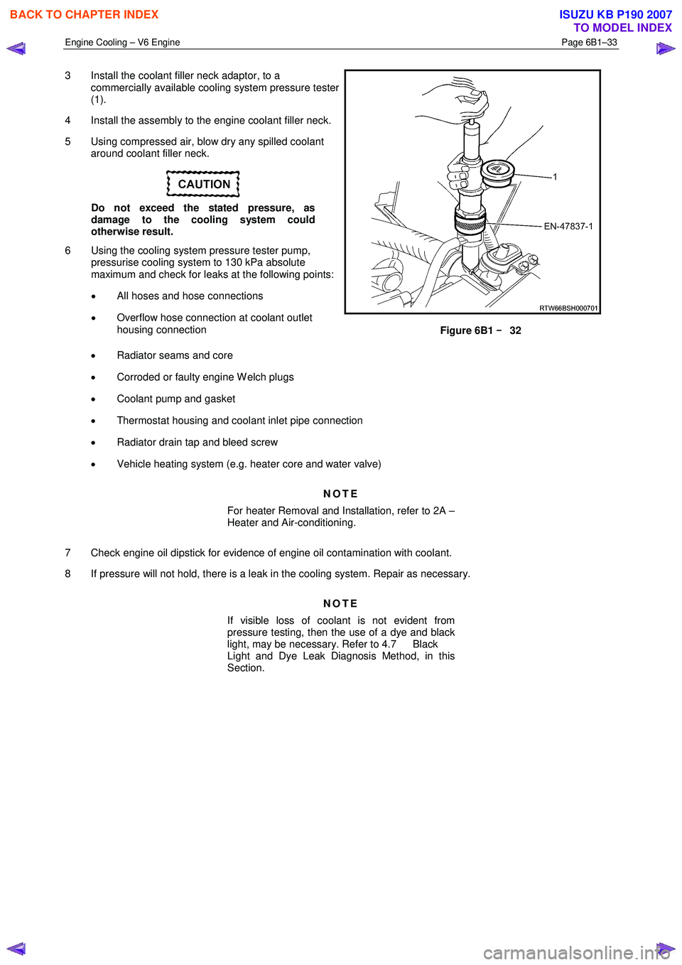
3 Install the coolant filler neck adaptor, to a
commercially available cooling system pressure tester
(1).
4 Install the assembly to the engine coolant filler neck.
5 Using compressed air, blow dry any spilled coolant around coolant filler neck.
Do not exceed the stated pressure, as
damage to the cooling system could
otherwise result.
6 Using the cooling system pressure tester pump, pressurise cooling system to 130 kPa absolute
maximum and check for leaks at the following points:
• All hoses and hose connections
• Overflow hose connection at coolant outlet
housing connection
Figure 6B1 –
––
–
32
• Radiator seams and core
• Corroded or faulty engine W elch plugs
• Coolant pump and gasket
• Thermostat housing and coolant inlet pipe connection
• Radiator drain tap and bleed screw
• Vehicle heating system (e.g. heater core and water valve)
NOTE
For heater Removal and Installation, refer to 2A –
Heater and Air-conditioning.
7 Check engine oil dipstick for evidence of engine oil contamination with coolant.
8 If pressure will not hold, there is a leak in the cooling system. Repair as necessary.
NOTE
If visible loss of coolant is not evident from
pressure testing, then the use of a dye and black
light, may be necessary. Refer to 4.7 Black
Light and Dye Leak Diagnosis Method, in this
Section.
BACK TO CHAPTER INDEX
TO MODEL INDEX
ISUZU KB P190 2007
Page 3176 of 6020
Engine Cooling – V6 Engine Page 6B1–41
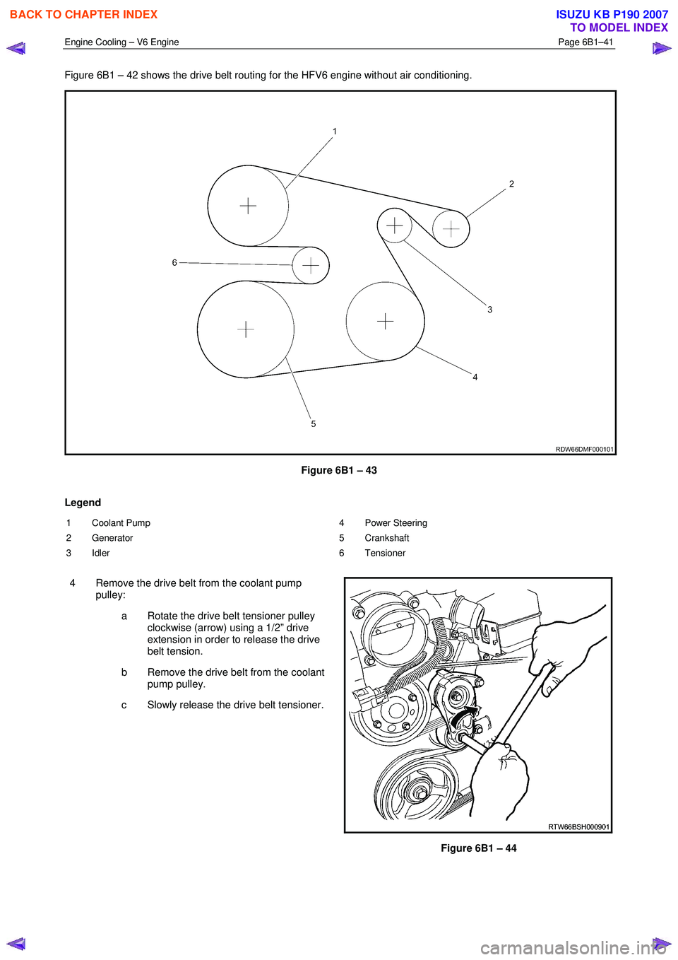
Figure 6B1 – 42 shows the drive belt routing for the HFV6 engine without air conditioning.
Figure 6B1 – 43
Legend
1 Coolant Pump
2 Generator
3 Idler 4 Power Steering
5 Crankshaft
6 Tensioner
4 Remove the drive belt from the coolant pump pulley:
a Rotate the drive belt tensioner pulley clockwise (arrow) using a 1/2” drive
extension in order to release the drive
belt tension.
b Remove the drive belt from the coolant pump pulley.
c Slowly release the drive belt tensioner.
Figure 6B1 – 44
BACK TO CHAPTER INDEX
TO MODEL INDEX
ISUZU KB P190 2007