2007 ISUZU KB P190 air condition
[x] Cancel search: air conditionPage 2488 of 6020
Engine Mechanical – V6 Page 6A1–9
• Faulty operation or performance of any systems or components which depend on the proper operation or
performance of the system or component under repair,
• Damage to fasteners, basic tools or special tools and / or
• Leakage of coolant, lubricant or other vital fluids.
NOTE defined
A NOTE statement immediately precedes or follows an operating procedure, maintenance practice or condition that
requires highlighting. A NOTE statement also emphasises necessary characteristics of a diagnostic or repair procedure.
A NOTE statement is designed to:
• Clarify a procedure,
• Present additional information for accomplishing a procedure,
• Give insight into the reasons for performing a procedure in the recommended manner, and / or
Present information that gives the technician the benefit of past experience in accomplishing a procedure with greater
ease.
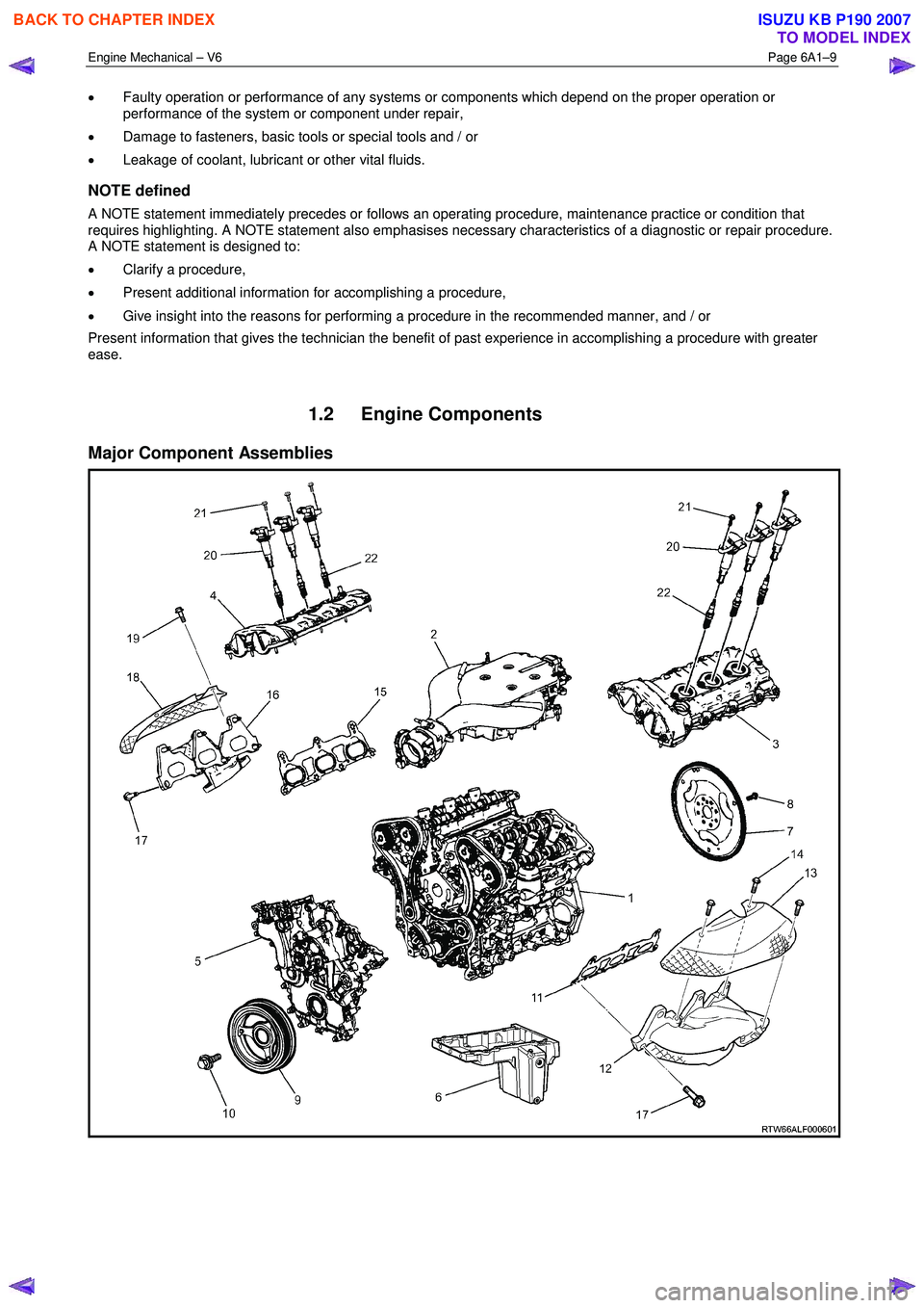
1.2 Engine Components
Major Component Assemblies
BACK TO CHAPTER INDEX
TO MODEL INDEX
ISUZU KB P190 2007
Page 2503 of 6020
Engine Mechanical – V6 Page 6A1–24
1.5 Engine Lubrication System
Lubrication Description
A structural diecast aluminium oil pan is fitted that incorporates an oil suction pipe, an oil deflector and an oil level sensor.
The oil suction pipe is bolted into the oil pan and seals to the bottom of the cylinder block with a gasket. The oil deflector
is bolted to the upper portion of the oil pan and ensures oil supply is maintained under all conditions. The oil level sensor
is mounted through the bottom of the oil pan.
A crankshaft driven gerotor oil pump is mounted to the front of the cylinder block. The pump, which incorporates an
internal pressure-relief valve, draws oil from the oil suction tube through the lower passage in the cylinder block. Oil is
then directed through an upper passage to the left-hand side of the cylinder block where the oil filter adapter is mounted.
The oil filter adapter incorporates a top-access, cartridge style oil filter. The filter is accessed through a screw-on cap tha t
incorporates an oil bypass valve. The oil filter adapter housing incorporates a drain back control valve and a threaded oil
pressure sender. Oil flows through a lower passage within the oil filter adapter and through the oil filter cartridge. Filtered
oil travels back through the upper passage of the adapter and into the engine block.
Oil is then directed up and across the front of the cylinder block, through several drilled passages. These front passages
feed oil to each cylinder head, the passage for the main bearings and piston oil jets, the right-hand and left-hand
secondary idler sprockets and to the primary timing chain tensioner.
Each cylinder head passage directs oil into oiling circuits for the stationary hydraulic lash adjusters (SHLAs) and the
camshaft bearing journals. An additional passage in the cylinder head also directs oil to the secondary timing chain
tensioner.
The oil passage that supplies oil to the main bearings also supplies oil to pressure actuated piston cooling oil jets. Each
oil jet is mounted between opposing cylinder bores and directs oil to the two bores to provide extra cooling and control
piston temperatures.
From the front passages, oil is directed to the front of the block where the right-hand and left-hand intermediate drive
shaft sprockets and the primary timing chain tensioner are mounted. Each camshaft timing chain tensioner relies on a
gasket to maintain an oil reserve after the engine is turned off. All camshaft timing chain tensioners incorporate a small
oil jet to supply an oil spray onto the camshaft timing chain components.
Oil returns to the oil pan, either through the camshaft timing chain area or through the drain back passages on the
outboard walls of the cylinder heads and cylinder block.
1.6 Service Notes
Cleanliness and Care
Throughout this Section, correct cleaning and protection of machined surfaces and friction areas is a part of the repair
procedure. This is considered standard workshop practice, even if not specifically stated.
W hen any internal engine part is serviced, care and cleanliness is extremely important.
W hen components are removed for service, they should be marked, organised or retained in a specific order for
reassembly.
At the time of installation, components should be installed in the same location and with the same mating surface as
when removed.
Any engine is a combination of many machined, honed, polished and lapped surfaces with tolerances that are measured
in thousandths of a millimetre. These surfaces should be covered or protected to avoid component damage.
A liberal coating of clean engine oil should be applied to friction areas during assembly, as the lubrication will protect and
lubricate friction surfaces during the initial engine start-up.
Replacing Engine Gaskets
Re-Using Gaskets and Applying Sealants
• do not reuse any gasket unless specified,
• gaskets that can be reused will be identified in the service procedure, and
• do not apply sealant to any gasket or sealing surface unless specified in the service information.
Separating Components
• Use a rubber mallet to separate components.
• Bump the part sideways to loosen the components.
• Bumping should be done at bends or reinforced areas to prevent distortion of parts.
Cleaning Gasket Surfaces
• W here required, remove all gasket and sealing material from the part using a plastic or wood scraper.
• Care must be used to avoid gouging or scraping the sealing surfaces.
BACK TO CHAPTER INDEX
TO MODEL INDEX
ISUZU KB P190 2007
Page 2507 of 6020
Engine Mechanical – V6 Page 6A1–28
2 Diagnosis
2.1 Engine Diagnosis
Begin engine mechanical system diagnosis by reviewing the disassembled views provided in 1.2 Engine Components
and 1.4 Engine Construction. Reviewing the description and operation information provided will assist in determining
whether the condition described by the customer is a fault or normal engine operation.
2.2 Symptoms
Strategy Based Diagnosis
1 Review the system operations to familiarise yourself with the system functions, refer to 1 General Information and 6C1-1 Engine Management General Information.
2 Perform an engine management Diagnostic System Check, refer to 6C1-2 Engine Management – V6 – Diagnostics.
All diagnosis on a vehicle should follow a logical process. Strategy based diagnosis is a uniform approach for repairing
all vehicle systems. The strategy based diagnostic flow chart may always be used to resolve a system problem. The
diagnostic flow chart is the place to start when repairs are required. For a detailed explanation of strategy based
diagnosis and the flow chart, refer to 6C1-2 Engine Management – V6 – Diagnostics.
Visual / Physical Inspection
1 Inspect the vehicle for aftermarket accessories which may adversely affect engine operation.
2 Inspect the easily accessible or visible system components for obvious signs of damage or conditions that may cause the symptom.
3 Check the engine lubrication system for the following:
• correct oil level,
• correct lubricant viscosity,
• correct oil filter application, and
• contaminated or burnt oil.
4 Confirm the exact operating conditions under which the fault occurs. Note factors such as:
• engine speed (r.p.m.),
• ambient temperature,
• engine temperature,
• engine warm-up time, and
• vehicle road speed.
5 Compare the engine sounds, if applicable, to a known good engine, and ensure you are not trying to diagnose a normal operating condition.
Intermittent
For intermittent faults, test the vehicle under the same conditions the customer reported in order to confirm whether the
system is operating correctly.
BACK TO CHAPTER INDEX
TO MODEL INDEX
ISUZU KB P190 2007
Page 2508 of 6020
Engine Mechanical – V6 Page 6A1–29
2.3 Engine Misfire without Internal Engine
Noises
Cause Correction
Abnormalities, severe cracking, bumps or missing areas in
the accessory drive belt.
Abnormalities in the accessory drive system and/or
components may cause engine speed variations that result
in a misfire diagnostic trouble code (DTC). A misfire code
may be present without an actual misfire condition. Replace the accessory drive belt, refer to 3.5
Accessory
Drive Belt.
Refer to 6C1-2 Engine Management – V6 – Diagnostics to
check for DTCs.
W orn, damaged or misaligned accessory drive components
and excessive pulley run-out may lead to a misfire DTC.
A misfire code may be present without an actual misfire
condition. Inspect the components and repair or replace as required.
Refer to 6C1-2 Engine Management – V6 – Diagnostics to
check for DTCs.
Loose or incorrectly fitted flexplate or crankshaft balancer
assembly.
A misfire DTC may be present without an actual misfire
condition. Repair or replace the flexplate or crankshaft balancer as
required, refer to 3.13 Crankshaft Balancer Assembly
or 4.3 Flexplate Assembly.
Refer to 6C1-2 Engine Management – V6 – Diagnostics to
check for DTCs
Restricted exhaust system.
A severe restriction in the exhaust flow can cause
significant loss of engine performance and may set a DTC.
Possible causes of restrictions in the exhaust system
include collapsed/dented pipes and blocked mufflers and/or
catalytic converters. Repair or replace exhaust system components as required,
refer to 8B Exhaust System.
Refer to 6C1-2 Engine Management – V6 – Diagnostics to
check for DTCs
Incorrectly installed or damaged vacuum hoses. Repair or replace vacuum hoses as required.
Incorrect sealing between the intake manifold and cylinder
heads, upper intake manifold and lower intake manifold,
throttle body and intake manifold. Repair or replace the intake manifold, throttle body gaskets,
cylinder heads, throttle body as required.
Incorrectly installed or damaged barometric
pressure(BARO) sensor and/or seal. The seal should not
be torn or damaged. Repair or replace the BARO sensor and/or seal as
required, refer to 6C1-3 Engine Management – V6 –
Service Operations.
Incorrectly installed or damaged EVAP purge solenoid
and/or O-ring seal. Repair or replace the EVAP purge solenoid and/or seal as
required, refer to 6C1-3 Engine Management – V6 –
Service Operations
W orn or loose stationary hydraulic lash adjusters (SHLA)
and/or rocker arms.
The SHLAs, rocker arms and roller bearings should be
intact and in the correct position. Replace the SHLAs and/or rocker arms as required, refer to
3.21 Stationary Hydraulic Lash Adjuster or 3.20
Rocker Arm.
Stuck valves.
Carbon build up on the valve stems can result in the valves
not closing correctly. Repair or replace as required, refer to 3.22 Cylinder Head
Assembly.
Excessively worn or misaligned timing chain/s. Replace the timing chain/s and components as required,
refer to 3.16 Timing Chains, Tensioners, Shoes and
Guides.
W orn camshaft lobes. Replace the camshaft/s and SHLAs as required, refer to
3.19 Camshaft or 3.21 Stationary Hydraulic Lash
Adjuster.
Excessive oil pressure.
A lubrication system with excessive oil pressure may lead
to excessive lash adjuster pump-up and loss of
compression. 1 Perform an oil pressure test, refer to 3.1
Engine Oil.
2 Repair or replace the engine oil pump as required, refer to 3.17 Oil Pump Assembly.
BACK TO CHAPTER INDEX
TO MODEL INDEX
ISUZU KB P190 2007
Page 2509 of 6020
Engine Mechanical – V6 Page 6A1–30
Cause Correction
Faulty cylinder head gasket and/or cracking or other
damage to the cylinder head and cylinder block coolant
passages.
Coolant consumption may or may not cause the engine to
overheat. 1 Inspect the spark plugs for coolant saturation, refer to
6C1-3 Engine Management – V6 – Service
Operations.
2 Inspect the cylinder heads, cylinder block and/or head gaskets, refer to 3.22 Cylinder Head Assembly and/or
4.7 Cylinder Block.
3 Repair or replace components as required.
W orn piston rings.
Oil consumption may or may not cause the engine to
misfire. 1 Inspect the spark plugs for oil deposits, refer to 6C1-3
Engine Management – V6 – Service Operations.
2 Check the cylinders for a loss of compression, refer to 2.15 Engine Compression Test.
3 Perform compression testing to identify the cause of low compression.
4 Repair or replace components as required.
A damaged crankshaft reluctor wheel.
A damaged crankshaft reluctor wheel can result in different
symptoms depending on the severity and location of the
damage.
Systems with severe reluctor ring damage may exhibit
periodic loss of crankshaft position, stop delivering a signal,
and then re-sync the crankshaft position.
Systems with slight reluctor ring damage may exhibit no
loss of crankshaft position and no misfire may occur,
however, a DTC may set. Replace the crankshaft as required, refer to 4.6
Crankshaft and Main Bearings.
Refer to 6C1-2 Engine Management – V6 – Diagnostics to
check for DTCs
2.4 Engine Misfire with Abnormal Internal Lower Engine Noises
Cause Correction
Abnormalities, severe cracking, bumps or missing areas in
the accessory drive belt.
Abnormalities in the accessory drive system and/or
components may cause engine speed variations that result
in a misfire diagnostic trouble code (DTC). A misfire code
may be present without an actual misfire condition. Replace the accessory drive belt, refer to 3.5
Accessory
Drive Belt.
Refer to 6C1-2 Engine Management – V6 – Diagnostics to
check for DTCs
W orn, damaged or misaligned accessory drive components
and excessive pulley run-out may lead to a misfire DTC.
A misfire code may be present without an actual misfire
condition. Inspect the components and repair or replace as required.
Refer to 6C1-2 Engine Management – V6 – Diagnostics to
check for DTCs
Loose or Incorrectly fitted flexplate or crankshaft balancer
assembly.
A misfire code may be present without an actual misfire
condition. Repair or replace the flexplate or crankshaft balancer as
required, refer to 3.13 Crankshaft Balancer Assembly
or 4.3 Flexplate Assembly.
W orn or broken piston rings.
Oil consumption may or may not cause an actual misfire. 1 Inspect the spark plugs for oil deposits, refer to 6C1-3
Engine Management – V6 – Service Operations.
2 Check the cylinders for a loss of compression, refer to 2.15 Engine Compression Test.
3 Perform compression testing to identify the cause of low compression.
4 Repair or replace components as required.
W orn crankshaft thrust bearing.
Severely worn thrust surfaces on the crankshaft and/or
thrust bearing may permit fore and aft movement of the
crankshaft and create a DTC without an actual misfire
condition being present. Replace the crankshaft and/or bearings as required, refer to
4.6 Crankshaft and Main Bearings.
Refer to 6C1-2 Engine Management – V6 – Diagnostics to
check for DTCs
BACK TO CHAPTER INDEX
TO MODEL INDEX
ISUZU KB P190 2007
Page 2516 of 6020
Engine Mechanical – V6 Page 6A1–37
2.13 Coolant in Combustion Chamber
Definition
Excessive white smoke and/or coolant type odour emitted from the exhaust pipe may indicate coolant in the combustion
chamber. Low coolant levels, an inoperative engine cooling fan or a faulty thermostat may lead to an over-temperature
condition which may cause internal engine component damage. A slower than normal cranking speed may indicate
coolant entering the combustion chamber.
1 Remove the spark plugs and inspect for spark plugs saturated by coolant and coolant in the cylinder bore.
2 Inspect by performing a cylinder leakage test, refer to 2.16 Cylinder Leakage Test. During this test, excessive air bubbles in the coolant may indicate a faulty head gasket, cracked cylinder head or cracked cylinder
block.
3 Inspect by performing a cylinder compression test. Two cylinders side-by-side on the cylinder block, with low compression, may indicate a failed cylinder head gasket, refer to 2.15 Engine Compression Test.
Cause Correction
Cracked intake manifold or faulty gasket. Replace components as required, refer to 3.10
Intake Manifold Assembly – Complete.
Faulty cylinder head gasket. Replace the cylinder head gasket, refer to 3.22
Cylinder Head Assembly.
W arped cylinder head. Repair or replace the cylinder heads as required, refer to
3.22 Cylinder Head Assembly.
Cracked cylinder liner or block Repair or replace the cylinder block and components as
required, refer to 4.7 Cylinder Block.
Cylinder head or cylinder block porosity. Repair or replace the cylinder block or cylinder heads as
required, refer to 4.7 Cylinder Block or 3.22
Cylinder Head Assembly.
2.14 Coolant in Engine Oil
Definition
Foamy or discoloured oil or an engine oil overfill condition may indicate coolant entering the engine crankcase. Low
coolant levels, an inoperative engine cooling fan or a faulty thermostat may lead to an over-temperature condition which
may result in engine component damage. Contaminated engine oil and oil filters must be replaced.
1 Inspect the oil for excessive foaming or an overfill condition. Oil diluted by coolant may not correctly lubricate the crankshaft bearings, resulting in component damage, refer to 2.10 Lower Engine Noise, Regardless of Engine
Speed.
2 Perform a cylinder leakage test, refer to 2.16 Cylinder Leakage Test. During this procedure, excessive air bubbles in the engine coolant may indicate a faulty gasket or damaged component.
3 Perform a cylinder compression test. Two cylinders side-by-side on the cylinder block, with low compression, may indicate a failed cylinder head gasket, refer to 2.15 Engine Compression Test.
Cause Correction
Faulty cylinder head gasket. Replace the cylinder head gasket, refer to 3.22
Cylinder Head Assembly.
W arped cylinder head. Repair or replace the cylinder heads as required, refer to
3.22 Cylinder Head Assembly.
Cracked cylinder liner or block Repair or replace the cylinder block and components as
required, refer to 4.7 Cylinder Block.
Cylinder head, cylinder block or intake manifold porosity. Repair or replace the cylinder block, cylinder heads or intake manifold components as required, refer to 4.7
Cylinder Block, 3.22 Cylinder Head
Assembly or 3.10 Intake Manifold Assembly – Complete.
BACK TO CHAPTER INDEX
TO MODEL INDEX
ISUZU KB P190 2007
Page 2518 of 6020

Engine Mechanical – V6 Page 6A1–39
2.16 Cylinder Leakage Test
A leakage test may be performed to measure cylinder/combustion chamber leakage. High cylinder leakage may indicate
one or more of the following:
• worn or burnt valves,
• broken valve springs,
• stuck valve lifters,
• incorrect valve lash/adjustment,
• damaged piston,
• worn piston rings,
• worn or scored cylinder bore,
• damaged cylinder head gasket,
• cracked or damaged cylinder head, or
• cracked or damaged engine block.
1 Disconnect the battery ground negative cable.
2 Remove the spark plugs from all cylinders, refer to 6C1-3 Engine Management – V6 – Service Operations.
3 Rotate the crankshaft to place the piston in the cylinder being tested at top dead centre (TDC) of the compression stroke.
4 Install a commercially available cylinder head leak down tester into the spark plug hole.
NOTE
If required, hold the crankshaft balancer bolt to
prevent the engine from rotating.
5 Apply shop air pressure to the cylinder head leak down tester and adjust according to the manufacturers instructions.
6 Record the cylinder leakage value. Cylinder leakage that exceeds 25 percent is considered excessive and may require component service. In excessive leakage situations, inspect for the following conditions:
• air leakage sounds at the throttle body or air inlet duct that may indicate a worn or burnt intake valve or a
broken valve spring,
• air leakage sounds at the exhaust system tailpipe that may indicate a worn or burnt exhaust valve or a broken
valve spring,
• air leakage sounds from the crankcase, oil level indicator tube, or oil fill tube that may indicate worn piston
rings, a damaged piston, a worn or scored cylinder bore, a damaged engine block or a damaged cylinder
head, or
• air bubbles in the cooling system may indicate a damaged cylinder head or a damaged cylinder head gasket.
7 Perform the leakage test on the remaining cylinders and record the values.
2.17 Engine Oil Consumption Diagnosis
Definition
Excessive oil consumption (not due to leaks) is the use of 3 litres or more of engine oil within 10,000 kilometres. Prior to
performing oil pressure testing, a preliminary inspection of the vehicle should be performed. During the preliminary visual
inspection, the following likely causes of excessive oil usage should be investigated.
Cause Correction
External oil leaks. Refer to 2.18 Engine Oil Leak Diagnosis.
Incorrect oil level or reading of the oil level indicator. Check for the correct oil level, refer to 3.1 Engine Oil.
Incorrect oil viscosity. Replace the engine oil, using the recommended SAE grade
of engine oil, refer to 3.1 Engine Oil.
Continuous high-speed driving or severe usage. Service vehicle more frequently, refer to 0B Lubrication and
Service.
Crankcase ventilation system restricted or malfunctioning. Repair or replace crankcase ventilation system components as required, refer to 6C1-3 Engine Management – V6 –
Service Operations.
BACK TO CHAPTER INDEX
TO MODEL INDEX
ISUZU KB P190 2007
Page 2521 of 6020
Engine Mechanical – V6 Page 6A1–42
2.19 Engine Oil Pressure Diagnosis
If the engine oil pressure is below the specified value, inspect the engine and components for the following:
• loose oil filter adaptor bolts,
• faulty oil filter adaptor seals,
• worn or faulty oil pump,
• loose oil pump bolts,
• loose, blocked or damaged oil pump suction pipe,
• faulty oil pump suction pipe seal,
• faulty oil pump pressure relief valve,
• faulty or incorrectly installed oil gallery plugs,
• excessive bearing clearance in one of the following:
• connecting rods big end/s,
• crankshaft main journal/s,
• camshaft/s,
• camshaft sprocket/s, and
• cracked, porous or restricted oil galleries, or broken lash adjuster/s.
2.20 Accessory Drive Belt Diagnosis
Tension Check
NOTE
An accessory drive belt that squeaks when the
engine is started or stopped is considered normal
and has no effect on drive belt durability.
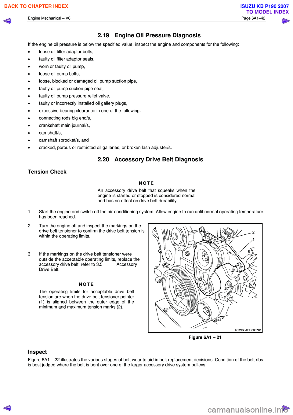
1 Start the engine and switch off the air-conditioning system. Allow engine to run until normal operating temperature has been reached.
2 Turn the engine off and inspect the markings on the drive belt tensioner to confirm the drive belt tension is
within the operating limits.
3 If the markings on the drive belt tensioner were outside the acceptable operating limits, replace the
accessory drive belt, refer to 3.5 Accessory
Drive Belt.
NOTE
The operating limits for acceptable drive belt
tension are when the drive belt tensioner pointer
(1) is aligned between the outer edge of the
minimum and maximum tension marks (2).
Figure 6A1 – 21
Inspect
Figure 6A1 – 22 illustrates the various stages of belt wear to aid in belt replacement decisions. Condition of the belt ribs
is best judged where the belt is bent over one of the larger accessory drive system pulleys.
BACK TO CHAPTER INDEX
TO MODEL INDEX
ISUZU KB P190 2007