2007 ISUZU KB P190 torque
[x] Cancel search: torquePage 3666 of 6020
Powertrain Interface Module – V6 Page 6E1–5
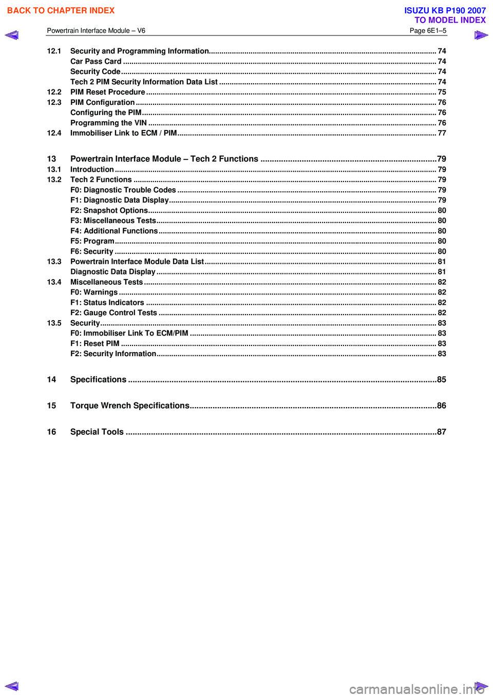
12.1 Security and Programming Information............................................................................................................. 74
Car Pass Card ...................................................................................................................................................... 74
Security Code ....................................................................................................................................................... 74
Tech 2 PIM Security Information Data List ...................................................................................... .................. 74
12.2 PIM Reset Procedure ........................................................................................................................................... 75
12.3 PIM Configuration ................................................................................................................................................ 76
Configuring the PIM ............................................................................................................ ................................. 76
Programming the VIN ............................................................................................................ .............................. 76
12.4 Immobiliser Link to ECM / PIM .................................................................................................. .......................... 77
13 Powertrain Interface Module – Tech 2 Functions .............................................................................79
13.1 Introduction .......................................................................................................................................................... 79
13.2 Tech 2 Functions ............................................................................................................... .................................. 79
F0: Diagnostic Trouble Codes ................................................................................................... ......................... 79
F1: Diagnostic Data Display................................................................................................................................ 79
F2: Snapshot Options.......................................................................................................................................... 80
F3: Miscellaneous Tests........................................................................................................ .............................. 80
F4: Additional Functions ..................................................................................................................................... 80
F5: Program .......................................................................................................................................................... 80
F6: Security .......................................................................................................................................................... 80
13.3 Powertrain Interface Module Data List .......................................................................................... ..................... 81
Diagnostic Data Display ...................................................................................................................................... 81
13.4 Miscellaneous Tests ............................................................................................................................................ 82
F0: Warnings ........................................................................................................................................................ 82
F1: Status Indicators .......................................................................................................... ................................. 82
F2: Gauge Control Tests ........................................................................................................ ............................. 82
13.5 Security................................................................................................................................................................. 83
F0: Immobiliser Link To ECM/PIM ................................................................................................ ...................... 83
F1: Reset PIM ....................................................................................................................................................... 83
F2: Security Information ....................................................................................................... ............................... 83
14 Specifications .......................................................................................................................................85
15 Torque Wrench Specifications................................................................................................... .........86
16 Special Tools ........................................................................................................................................87
BACK TO CHAPTER INDEX
TO MODEL INDEX
ISUZU KB P190 2007
Page 3713 of 6020
Powertrain Interface Module – V6 Page 6E1–52
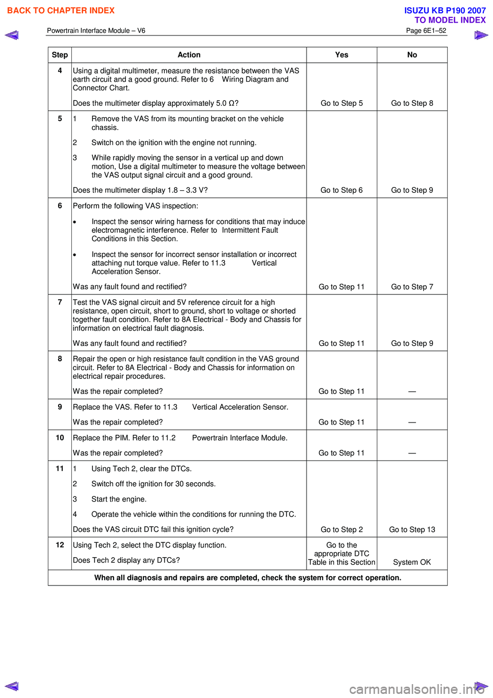
Step Action Yes No
4
Using a digital multimeter, measure the resistance between the VAS
earth circuit and a good ground. Refer to 6 W iring Diagram and
Connector Chart.
Does the multimeter display approximately 5.0 Ω?
Go to Step 5 Go to Step 8
5
1 Remove the VAS from its mounting bracket on the vehicle
chassis.
2 Switch on the ignition with the engine not running.
3 W hile rapidly moving the sensor in a vertical up and down motion, Use a digital multimeter to measure the voltage between
the VAS output signal circuit and a good ground.
Does the multimeter display 1.8 – 3.3 V? Go to Step 6 Go to Step 9
6 Perform the following VAS inspection:
• Inspect the sensor wiring harness for conditions that may induce
electromagnetic interference. Refer to Intermittent Fault
Conditions in this Section.
• Inspect the sensor for incorrect sensor installation or incorrect
attaching nut torque value. Refer to 11.3 Vertical
Acceleration Sensor.
W as any fault found and rectified? Go to Step 11 Go to Step 7
7
Test the VAS signal circuit and 5V reference circuit for a high
resistance, open circuit, short to ground, short to voltage or shorted
together fault condition. Refer to 8A Electrical - Body and Chassis for
information on electrical fault diagnosis.
W as any fault found and rectified? Go to Step 11 Go to Step 9
8
Repair the open or high resistance fault condition in the VAS ground
circuit. Refer to 8A Electrical - Body and Chassis for information on
electrical repair procedures.
W as the repair completed? Go to Step 11 —
9 Replace the VAS. Refer to 11.3 Vertical Acceleration Sensor.
W as the repair completed? Go to Step 11 —
10 Replace the PIM. Refer to 11.2 Powertrain Interface Module.
W as the repair completed? Go to Step 11 —
11 1 Using Tech 2, clear the DTCs.
2 Switch off the ignition for 30 seconds.
3 Start the engine.
4 Operate the vehicle within the conditions for running the DTC.
Does the VAS circuit DTC fail this ignition cycle? Go to Step 2 Go to Step 13
12
Using Tech 2, select the DTC display function.
Does Tech 2 display any DTCs? Go to the
appropriate DTC
Table in this Section System OK
When all diagnosis and repairs are completed, check the system for correct operation.
BACK TO CHAPTER INDEX
TO MODEL INDEX
ISUZU KB P190 2007
Page 3715 of 6020
Powertrain Interface Module – V6 Page 6E1–54
• For an intermittent fault condition, refer to Intermittent Fault Conditions in this Section.
• The VSS in conjunction with the 40X reluctor wheel generates an AC signal voltage. The amplitude and frequency
of the signal generated is proportional to the vehicle speed. The PIM uses this signal from the VSS signal circuit to
determine the vehicle speed.
• Since fault condition in a wiring connector may trigger DTCs, always test the connectors related to this diagnostic
procedure for shorted terminals or poor wiring connection before replacing any component. Refer to 8A Electrical -
Body and Chassis for information on electrical fault diagnosis.
• To assist diagnosis, refer to 6 W iring Diagram and Connector Chart in this Section, for the system wiring diagram
and connector charts.
Test Description
The following numbers refer to the step numbers in the diagnostic table:
3 The PIM supplies 2.5 V to signal circuit of the VSS circuit to reduce the Electro Magnetic interference (EMI). If the voltage is not within range, this indicates there is an PIM fault or a PIM circuit fault condition.
4 The PIM supplies 2.5 V to low reference circuit of the VSS circuit to reduce the Electro Magnetic interference (EMI). If the voltage is not within range, this indicates there is a PIM fault or a PIM circuit fault condition.
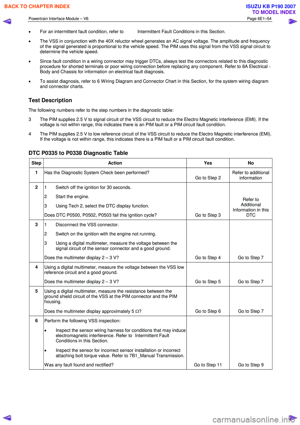
DTC P0335 to P0338 Diagnostic Table
Step Action Yes No
1
Has the Diagnostic System Check been performed?
Go to Step 2 Refer to additional
information
2 1 Switch off the ignition for 30 seconds.
2 Start the engine.
3 Using Tech 2, select the DTC display function.
Does DTC P0500, P0502, P0503 fail this ignition cycle? Go to Step 3 Refer to
Additional
Information in this DTC
3 1 Disconnect the VSS connector.
2 Switch on the ignition with the engine not running.
3 Using a digital multimeter, measure the voltage between the signal circuit of the sensor connector and a good ground.
Does the multimeter display 2 – 3 V? Go to Step 4 Go to Step 7
4 Using a digital multimeter, measure the voltage between the VSS low
reference circuit and a good ground.
Does the multimeter display 2 – 3 V? Go to Step 5 Go to Step 7
5 Using a digital multimeter, measure the resistance between the
ground shield circuit of the VSS at the PIM connector and the PIM
housing.
Does the multimeter display approximately 5 Ω? Go to Step 6 Go to Step 7
6
Perform the following VSS inspection:
• Inspect the sensor wiring harness for conditions that may induce
electromagnetic interference. Refer to Intermittent Fault
Conditions in this Section.
• Inspect the sensor for incorrect sensor installation or incorrect
attaching bolt torque value. Refer to 7B1_Manual Transmission.
W as any fault found and rectified? Go to Step 11 Go to Step 9
BACK TO CHAPTER INDEX
TO MODEL INDEX
ISUZU KB P190 2007
Page 3733 of 6020
Powertrain Interface Module – V6 Page 6E1–72
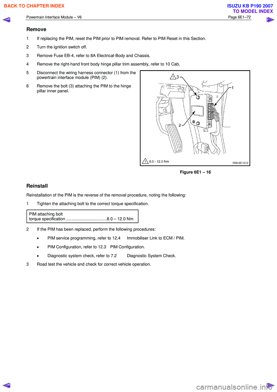
Remove
1 If replacing the PIM, reset the PIM prior to PIM removal. Refer to PIM Reset in this Section.
2 Turn the ignition switch off.
3 Remove Fuse EB-4, refer to 8A Electrical-Body and Chassis.
4 Remove the right-hand front body hinge pillar trim assembly, refer to 10 Cab.
5 Disconnect the wiring harness connector (1) from the powertrain interface module (PIM) (2).
6 Remove the bolt (3) attaching the PIM to the hinge pillar inner panel.
Figure 6E1 – 16
Reinstall
Reinstallation of the PIM is the reverse of the removal procedure, noting the following:
1 Tighten the attaching bolt to the correct torque specification.
PIM attaching bolt
torque specification ...................................8.0 – 12.0 Nm
2 If the PIM has been replaced, perform the following procedures: • PIM service programming, refer to 12.4 Immobiliser Link to ECM / PIM.
• PIM Configuration, refer to 12.3 PIM Configuration.
• Diagnostic system check, refer to 7.2 Diagnostic System Check.
3 Road test the vehicle and check for correct vehicle operation.
BACK TO CHAPTER INDEX
TO MODEL INDEX
ISUZU KB P190 2007
Page 3734 of 6020
Powertrain Interface Module – V6 Page 6E1–73
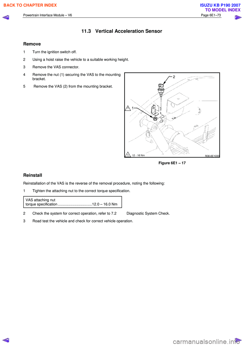
11.3 Vertical Acceleration Sensor
Remove
1 Turn the ignition switch off.
2 Using a hoist raise the vehicle to a suitable working height.
3 Remove the VAS connector.
4 Remove the nut (1) securing the VAS to the mounting bracket.
5 Remove the VAS (2) from the mounting bracket.
Figure 6E1 – 17
Reinstall
Reinstallation of the VAS is the reverse of the removal procedure, noting the following:
1 Tighten the attaching nut to the correct torque specification.
VAS attaching nut
torque specification .................................12.0 – 16.0 Nm
2 Check the system for correct operation, refer to 7.2 Diagnostic System Check.
3 Road test the vehicle and check for correct vehicle operation.
BACK TO CHAPTER INDEX
TO MODEL INDEX
ISUZU KB P190 2007
Page 3747 of 6020

Powertrain Interface Module – V6 Page 6E1–86
15 Torque Wrench Specifications
Powertrain Interface Module Attaching Screw ............................. 8.0 – 12.0 Nm
Vertical Acceleration Sensor attaching nut ............................... 12.0 – 16.0 Nm
BACK TO CHAPTER INDEX
TO MODEL INDEX
ISUZU KB P190 2007
Page 3749 of 6020
Exhaust System – V6 Page 6F – 1
6F
Exhaust System – V6
ATTENTION
Before performing any service operations or other procedure described in this Section, refer to
1.3 WARNING, CAUTION and NOTES for correct workshop practices with regard to safety and / or
property damage.
1 General Information ............................................................................................................ ...................2
1.1 Emission Reductions ............................................................................................................................................ 2
Euro 3 Emissions Standards ................................................................................................................................ 3
1.2 General Description ............................................................................................................ ................................... 4
Service Notes ......................................................................................................................................................... 5
1.3 WARNING, CAUTION and NOTES..................................................................................................... .................... 5
1.1 Definition of WARNING, CAUTION and NOTE Statements......................................................................... .. 5
W ARNING defined ............................................................................................................................................. 5
CAUTION defined .............................................................................................................................................. 5
NOTE defined .................................................................................................................................................... 6
2 Front and Centre Exhaust Pipe .................................................................................................. ...........7
Removal .................................................................................................................................................................. 7
Reinstallation ......................................................................................................................................................... 8
3 Silencer and Rear Exhaust Pipe............................................................................................................9
Removal .................................................................................................................................................................. 9
Reinstallation ......................................................................................................................................................... 9
4 Torque Wrench Specifications............................................................................................................10
BACK TO CHAPTER INDEX
TO MODEL INDEX
ISUZU KB P190 2007
Page 3751 of 6020
Exhaust System – V6 Page 6F – 3
The Catalytic converter can be damaged or
rendered ineffective, if:
• operated outside the limits of the closed
loop mixture control system
• the engine burns excessive amount of oil
• the exhaust temperature at the converter
is too high (exceeds 840°C).
The catalytic material is very sensitive to the effects of a rich or lean fuel mixture, which may cause the temperature of
the converter to rise rapidly. The catalytic converter normally operates at approximately 600 °C.
The catalytic converter is also sensitive to the use of leaded petrol. Using leaded fuel can cause deposits to form in the
converter, which restrict exhaust flow and prevent the catalyst from working. This will result in an increase in exhaust
backpressure and converter temperature.
NOTE
The use of unleaded petrol results in black
tailpipe deposits rather than the grey colour that
some people may normally associate with an
acceptable combustion condition. This black
colour resulting from the use of unleaded fuel
does not necessarily indicate a state of poor
engine tune. For V6 engines, Refer to: 6C1 – 1
Engine Management General Information.
Euro 3 Emissions Standards
The Euro 3 emissions standard is a European standard which aims at setting vehicle emissions targets to encourage
vehicle manufacturers to reduce harmful vehicle emissions such as Carbon Monoxide (CO), Hydrocarbons (HC) and the
various oxides of Nitrogen (NOx).
This vehicle is fitted with a supplemental
restraint system (SRS). Refer to section 9A
Restraints, in order to determine whether you
are performing service on or near the SRS
components or the SRS wiring.
Always use the correct fastener in the proper
location. When you replace a fastener, use
ONLY the exact part number for that
application. Isuzu will identify those fasteners
that require a replacement after removal and
fasteners that require thread lockers or thread
sealant. Unless otherwise specified, do not
use supplemental coatings (Paints, greases
or corrosion inhibitors) on thread fasteners or
fastener joints. Generally such coatings
adversely effect the fastener torque and the
joint clamping force, and may damage the
fastener. When you install fasteners, use the
correct tightening sequence and torque
specifications.
BACK TO CHAPTER INDEX
TO MODEL INDEX
ISUZU KB P190 2007