2007 ISUZU KB P190 torque
[x] Cancel search: torquePage 3783 of 6020
Automatic Transmission – 4L60E – General Information Page 7C1–23
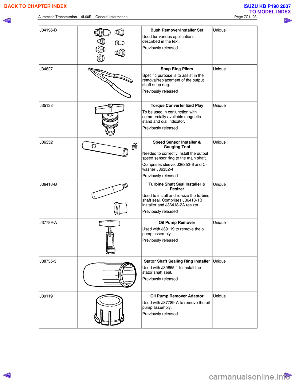
J34196-B
Bush Remover/Installer Set
Used for various applications,
described in the text.
Previously released Unique
J34627
Snap Ring Pliers
Specific purpose is to assist in the
removal/replacement of the output
shaft snap ring.
Previously released Unique
J35138
Torque Converter End Play
To be used in conjunction with
commercially available magnetic
stand and dial indicator.
Previously released Unique
J36352 Speed Sensor Installer &
Gauging Tool
Needed to correctly install the output
speed sensor ring to the main shaft.
Comprises sleeve, J36352-6 and C-
washer J36352-4.
Previously released Unique
J36418-B
Turbine Shaft Seal Installer &
Resizer
Used to install and re-size the turbine
shaft seal. Comprises J36418-1B
installer and J36418-2A resizer.
Previously released Unique
J37789-A
Oil Pump Remover
Used with J39119 to remove the oil
pump assembly.
Previously released Unique
J38735-3 Stator Shaft Sealing Ring Installer
Used with J39855-1 to install the
stator shaft seal.
Previously released Unique
J39119
Oil Pump Remover Adaptor
Used with J37789-A to remove the oil
pump assembly.
Previously released Unique
BACK TO CHAPTER INDEX
TO MODEL INDEX
ISUZU KB P190 2007
Page 3784 of 6020
Automatic Transmission – 4L60E – General Information Page 7C1–24
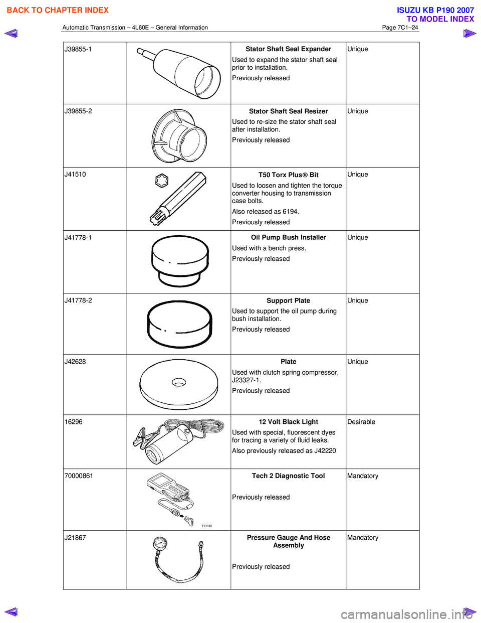
J39855-1
Stator Shaft Seal Expander
Used to expand the stator shaft seal
prior to installation.
Previously released Unique
J39855-2
Stator Shaft Seal Resizer
Used to re-size the stator shaft seal
after installation.
Previously released Unique
J41510
T50 Torx Plus
Bit
Used to loosen and tighten the torque
converter housing to transmission
case bolts.
Also released as 6194.
Previously released Unique
J41778-1
Oil Pump Bush Installer
Used with a bench press.
Previously released Unique
J41778-2
Support Plate
Used to support the oil pump during
bush installation.
Previously released Unique
J42628
Plate
Used with clutch spring compressor,
J23327-1.
Previously released Unique
16296 12 Volt Black Light
Used with special, fluorescent dyes
for tracing a variety of fluid leaks.
Also previously released as J42220 Desirable
70000861
Tech 2 Diagnostic Tool
Previously released Mandatory
J21867
Pressure Gauge And Hose
Assembly
Previously released Mandatory
BACK TO CHAPTER INDEX
TO MODEL INDEX
ISUZU KB P190 2007
Page 3789 of 6020
Automatic Transmission – 4L60E – Electrical Diagnosis Page 7C2–3
Circuit Description ............................................................................................................................................... 43
Conditions for Running the DTC ........................................................................................................................ 43
DTC P0711 ...................................................................................................................................................... 43
DTC P0712 ...................................................................................................................................................... 43
DTC P0713 ...................................................................................................................................................... 44
Conditions for Setting the DTC................................................................................................. .......................... 44
DTC P0711 ...................................................................................................................................................... 44
DTC P0712 ...................................................................................................................................................... 44
DTC P0713 ...................................................................................................................................................... 44
Action Taken When the DTC Sets ................................................................................................. ..................... 44
Conditions for Clearing the DTC ........................................................................................................................ 44
Diagnostic Aids .................................................................................................................................................... 45
Test Description ................................................................................................................................................... 45
DTC P0711 to P0713 Diagnostic Table ............................................................................................ ................... 45
4.14 DTC P0719 – Brake Switch Circuit High Input (Stuck On) ......................................................................... ....... 47
DTC Description ................................................................................................................................................... 47
Circuit Description ............................................................................................................................................... 47
Conditions for Running the DTC ................................................................................................. ....................... 47
Conditions for Setting the DTC........................................................................................................................... 47
Action Taken When the DTC Sets ................................................................................................. ..................... 47
Conditions for Clearing the DTC ........................................................................................................................ 47
Diagnostic Aids .................................................................................................................................................... 48
Test Description ................................................................................................................................................... 48
DTC P0719 Diagnostic Table..................................................................................................... .......................... 48
4.15 DTC P0722 – Vehicle Speed Sensor Circuit Low Voltage........................................................................... ...... 49
DTC Description ................................................................................................................................................... 49
Circuit Description ............................................................................................................................................... 49
Conditions for Running the DTC ................................................................................................. ....................... 49
Conditions for Setting the DTC........................................................................................................................... 49
Action Taken When the DTC Sets ................................................................................................. ..................... 50
Conditions for Clearing the DTC ........................................................................................................................ 50
Diagnostic Aids .................................................................................................................................................... 50
Test Description ................................................................................................................................................... 50
DTC P0722 Diagnostic Table..................................................................................................... .......................... 50
4.16 DTC P0723 – Vehicle Speed Sensor Circuit Intermittent .......................................................................... ........ 52
DTC Description ................................................................................................................................................... 52
Circuit Description ............................................................................................................................................... 52
Conditions for Running the DTC ................................................................................................. ....................... 52
Conditions for Setting the DTC........................................................................................................................... 53
Action Taken When the DTC Sets ................................................................................................. ..................... 53
Conditions for Clearing the DTC ........................................................................................................................ 53
Diagnostic Aids .................................................................................................................................................... 53
Test Description ................................................................................................................................................... 53
DTC P0723 Diagnostic Table..................................................................................................... .......................... 54
4.17 DTC P0724 – Brake Switch Circuit Low Input (Stuck Off) ................................................................................ 55
DTC Description ................................................................................................................................................... 55
Circuit Description ............................................................................................................................................... 55
Conditions for Running the DTC ................................................................................................. ....................... 56
Conditions for Setting the DTC........................................................................................................................... 56
Action Taken When the DTC Sets ................................................................................................. ..................... 56
Conditions for Clearing the DTC ........................................................................................................................ 56
Diagnostic Aids .................................................................................................................................................... 56
Test Description ................................................................................................................................................... 56
DTC P0724 Diagnostic Table..................................................................................................... .......................... 56
4.18 DTC P0741 – Torque Converter Clutch System – Stuck Off......................................................................... .... 57
DTC Description ................................................................................................................................................... 57
Circuit Description ............................................................................................................................................... 57
Conditions for Running the DTC ................................................................................................. ....................... 58
Conditions for Setting the DTC........................................................................................................................... 58
Action Taken When the DTC Sets ................................................................................................. ..................... 58
BACK TO CHAPTER INDEX
TO MODEL INDEX
ISUZU KB P190 2007
Page 3790 of 6020
Automatic Transmission – 4L60E – Electrical Diagnosis Page 7C2–4
Conditions for Clearing the DTC ........................................................................................................................ 58
Diagnostic Aids .................................................................................................................................................... 58
Test Description ................................................................................................................................................... 58
DTC P0741 Diagnostic Table..................................................................................................... .......................... 59
4.19 DTC P0742 – Torque Converter Clutch System – Stuck On .......................................................................... ... 60
DTC Description ................................................................................................................................................... 60
Circuit Description ............................................................................................................................................... 60
Conditions for Running the DTC ................................................................................................. ....................... 60
Conditions for Setting the DTC........................................................................................................................... 61
Action Taken When the DTC Sets ................................................................................................. ..................... 61
Conditions for Clearing the DTC ........................................................................................................................ 61
Diagnostic Aids .................................................................................................................................................... 61
Test Description ................................................................................................................................................... 61
DTC P0742 Diagnostic Table..................................................................................................... .......................... 61
4.20 DTC P0751 – 1-2 Shift Solenoid Valve Performance – No First or Fourth Gear ............................................. 63
DTC Description ................................................................................................................................................... 63
Circuit Description ............................................................................................................................................... 63
Conditions for Running the DTC ................................................................................................. ....................... 63
Conditions for Setting the DTC........................................................................................................................... 63
Action Taken When the DTC Sets ................................................................................................. ..................... 63
Conditions for Clearing the DTC ........................................................................................................................ 63
Diagnostic Aids .................................................................................................................................................... 64
Test Description ................................................................................................................................................... 64
DTC P0751 Diagnostic Table..................................................................................................... .......................... 64
4.21 DTC P0752 – 1-2 Shift Solenoid Valve Performance – No Second or Third Gear........................................... 65
DTC Description ................................................................................................................................................... 65
Circuit Description ............................................................................................................................................... 65
Conditions for Running the DTC ................................................................................................. ....................... 65
Conditions for Setting the DTC........................................................................................................................... 65
Action Taken When the DTC Sets ................................................................................................. ..................... 66
Conditions for Clearing the DTC ........................................................................................................................ 66
Diagnostic Aids .................................................................................................................................................... 66
Test Description ................................................................................................................................................... 66
DTC P0752 Diagnostic Table..................................................................................................... .......................... 66
4.22 DTC P0756 – 2-3 Shift Solenoid Valve Performance – No First or Second Gear ............................................ 68
DTC Description ................................................................................................................................................... 68
Circuit Description ............................................................................................................................................... 68
Conditions for Running the DTC ................................................................................................. ....................... 68
Conditions for Setting the DTC........................................................................................................................... 68
Action Taken When the DTC Sets ................................................................................................. ..................... 68
Conditions for Clearing the DTC ........................................................................................................................ 68
Diagnostic Aids .................................................................................................................................................... 69
Test Description ................................................................................................................................................... 69
DTC P0756 Diagnostic Table..................................................................................................... .......................... 69
4.23 DTC P0757 – 2-3 Shift Solenoid Valve Performance – No Third or Fourth Gear ............................................ 70
DTC Description ................................................................................................................................................... 70
Circuit Description ............................................................................................................................................... 70
Conditions for Running the DTC ................................................................................................. ....................... 71
Conditions for Setting the DTC........................................................................................................................... 71
Action Taken When the DTC Sets ................................................................................................. ..................... 71
Conditions for Clearing the DTC ........................................................................................................................ 71
Diagnostic Aids .................................................................................................................................................... 71
Test Description ................................................................................................................................................... 71
DTC P0757 Diagnostic Table..................................................................................................... .......................... 72
4.24 DTC P0787 – 3-2 Shift Solenoid Control Circuit Low Voltage .......................................................................... 73
DTC Description ................................................................................................................................................... 73
Circuit Description ............................................................................................................................................... 73
Conditions for Running the DTC ................................................................................................. ....................... 73
Conditions for Setting the DTC........................................................................................................................... 73
Action Taken When the DTC Sets ................................................................................................. ..................... 73
BACK TO CHAPTER INDEX
TO MODEL INDEX
ISUZU KB P190 2007
Page 3792 of 6020
Automatic Transmission – 4L60E – Electrical Diagnosis Page 7C2–6
DTC Description ................................................................................................................................................. 100
Circuit Description ............................................................................................................................................. 100
Conditions for Running the DTC ................................................................................................. ..................... 101
Conditions for Setting the DTC......................................................................................................................... 101
Action Taken When the DTC Sets ................................................................................................. ................... 101
Conditions for Clearing the DTC ...................................................................................................................... 101
Test Description ................................................................................................................................................. 101
DTC P0977 Diagnostic Table..................................................................................................... ........................ 101
4.32 DTC P1810, P1815 and P1816 – Transmission Fluid Pressure Position Switch........................................... 103
DTC Description ................................................................................................................................................. 103
Circuit Description ............................................................................................................................................. 103
Conditions for Running the DTC ................................................................................................. ..................... 104
DTC P1810 .................................................................................................................................................... 104
DTC P1815 .................................................................................................................................................... 104
DTC P1816 .................................................................................................................................................... 104
Conditions for Setting the DTC................................................................................................. ........................ 104
DTC P1810 .................................................................................................................................................... 104
DTC P1815 .................................................................................................................................................... 104
DTC P1816 .................................................................................................................................................... 104
Action Taken When the DTC Sets ................................................................................................. ................... 104
Conditions for Clearing the DTC ...................................................................................................................... 105
Diagnostic Aids .................................................................................................................................................. 105
Test Description ................................................................................................................................................. 105
DTC P1810, P1815 and P1816 Diagnostic Table.................................................................................... .......... 105
4.33 DTC P2763 – Torque Converter Clutch Pressure Control Solenoid Control Circuit High Voltage ............. 108
DTC Description ................................................................................................................................................. 108
Circuit Description ............................................................................................................................................. 108
Conditions for Running the DTC ................................................................................................. ..................... 108
Conditions for Setting the DTC......................................................................................................................... 108
Action Taken When the DTC Sets ................................................................................................. ................... 108
Conditions for Clearing the DTC ...................................................................................................................... 108
Test Description ................................................................................................................................................. 109
DTC P2763 Diagnostic Table..................................................................................................... ........................ 109
4.34 DTC P2764 – Torque Converter Clutch Pressure Control Solenoid Control Circuit Low Voltage .............. 111
DTC Description ................................................................................................................................................. 111
Circuit Description ............................................................................................................................................. 111
Conditions for Running the DTC ................................................................................................. ..................... 111
Conditions for Setting the DTC......................................................................................................................... 111
Action Taken When the DTC Sets ................................................................................................. ................... 111
Conditions for Clearing the DTC ...................................................................................................................... 111
Test Description ................................................................................................................................................. 112
DTC P2764 Diagnostic Table..................................................................................................... ........................ 112
4.35 DTC P2769 – Torque Converter Clutch Enable Solenoid Control Circuit Low Voltage ............................... 115
DTC Description ................................................................................................................................................. 115
Circuit Description ............................................................................................................................................. 115
Conditions for Running the DTC ................................................................................................. ..................... 115
Conditions for Setting the DTC......................................................................................................................... 115
Action Taken When the DTC Sets ................................................................................................. ................... 115
Conditions for Clearing the DTC ...................................................................................................................... 116
Diagnostic Aids .................................................................................................................................................. 116
Test Description ................................................................................................................................................. 116
DTC P2769 Diagnostic Table..................................................................................................... ........................ 116
4.36 DTC P2770 – Torque Converter Clutch Enable Solenoid Control Circuit High Voltage............................... 119
DTC Description ................................................................................................................................................. 119
Circuit Description ............................................................................................................................................. 119
Conditions for Running the DTC ................................................................................................. ..................... 119
Conditions for Setting the DTC......................................................................................................................... 119
Action Taken When the DTC Sets ................................................................................................. ................... 120
Conditions for Clearing the DTC ...................................................................................................................... 120
Test Description ................................................................................................................................................. 120
BACK TO CHAPTER INDEX
TO MODEL INDEX
ISUZU KB P190 2007
Page 3794 of 6020
Automatic Transmission – 4L60E – Electrical Diagnosis Page 7C2–8
1 General Information
1.1 Introduction
This Section covers the electrical diagnostic for the 4L60E automatic transmission when mated to a V6 engine.
1.2 General Description
The 4L60E automatic transmission incorporates electronic controls that utilise a transmission control module (TCM) to
control shift points through:
• the 1-2 and 2-3 shift solenoid valves,
• the 3-2 downshift solenoid valve,
• a torque converter clutch (TCC) solenoid valve,
• apply and release through the TCC pulse width modulated (PW M) solenoid valve, and
• line pressure through the pressure control (PC) solenoid valve.
Electrical signals from various sensors provide information to the TCM about the following:
• vehicle speed,
• throttle position,
• engine coolant temperature,
• transmission fluid temperature,
• gear range selector position,
• engine speed,
• converter turbine speed, and
• engine load braking and operating mode.
The TCM uses this information to determine the precise moment to upshift or downshift, apply or release the TCC and
what fluid pressure is needed to apply the clutches. This type of control provides consistent and precise shift points and
shift quality based on the operating conditions of the vehicle.
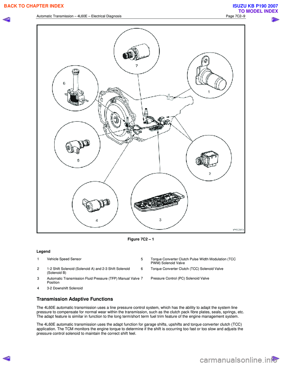
Figure 7C2 – 1 shows the location of the internal electronic components in the transmission.
BACK TO CHAPTER INDEX
TO MODEL INDEX
ISUZU KB P190 2007
Page 3795 of 6020
Automatic Transmission – 4L60E – Electrical Diagnosis Page 7C2–9
Figure 7C2 – 1
Legend
1 Vehicle Speed Sensor 5 Torque Converter Clutch Pulse Width Modulation (TCC
PWM) Solenoid Valve
2 1-2 Shift Solenoid (Solenoid A) and 2-3 Shift Solenoid (Solenoid B) 6 Torque Converter Clutch (TCC) Solenoid Valve
3
Automatic Transmission Fluid Pressure (TFP) Manual Valve
Position 7 Pressure Control (PC) Solenoid Valve
4 3-2 Downshift Solenoid
Transmission Adaptive Functions
The 4L60E automatic transmission uses a line pressure control system, which has the ability to adapt the system line
pressure to compensate for normal wear within the transmission, such as the clutch pack fibre plates, seals, springs, etc.
The adapt feature is similar in function to the long term/short term fuel trim feature of the engine management system.
The 4L60E automatic transmission uses the adapt function for garage shifts, upshifts and torque converter clutch (TCC)
application. The TCM monitors the engine torque to determine if the shift is occurring too fast or too slow and adjusts the
pressure control solenoid to maintain the correct shift feel.
BACK TO CHAPTER INDEX
TO MODEL INDEX
ISUZU KB P190 2007
Page 3796 of 6020
Automatic Transmission – 4L60E – Electrical Diagnosis Page 7C2–10
Limp Home Mode Description
If a major electrical system failure occurs which could affect vehicle safety or damage the transmission during normal
operation, the TCM enters a limp home mode. In the limp home mode, the transmission operates in the following
manner:
• The pressure control solenoid is off and the line pressure is at maximum to minimise clutch slippage.
• The TCC solenoid is off, therefore the torque converter clutch is disabled.
• The two shift solenoids are turned off. The transmission will operate in fourth gear if the vehicle has successfully
completed a 1-2 upshift in the current ignition cycle. If the vehicle has not completed a 1-2 upshift in the current
ignition cycle, the transmission will operate in third gear. If the transmission is operating in fourth gear, third gear
may be obtained if the engine is stopped briefly and re-started.
In limp home mode, the gear selector lever is ineffective at selecting forward gear ranges. In third or fourth gear, heat
builds up in the transmission quickly, particularly in stop and go traffic. Excessive heat build-up may cause transmission
failure if the vehicle is driven for extended distances in limp home mode.
1.3 Transmission Indicators and Messages
For information pertaining to the instrument cluster and the transmission information it displays, refer to the RA Rodeo
Owner Handbook.
1.4 Electronic Component Description
For all other electrical components not covered in this section, refer to General Motors Powertrain Group Electronically
Controlled Automatic Transmission Technician's Guide.
Transmission Control Module (TCM)
The Transmission Control Module (TCM) is located under the instrument panel, next to the brake pedal assembly and
connects directly to the transmission wiring harness. A single 49-way connector is used to make the connection between
the vehicle wiring harness and the TCM.
To access the connector for diagnosis:
1 Ensure the ignition switch is in the OFF position.
2 Disconnect the connector (1) from the transmission control module (TCM) (2) as follows, refer to Figure 7C2 – 2: a remove the securing pin (3),
b press the locking tab and swing the lever (4) to free the connector,
c remove the connector.
BACK TO CHAPTER INDEX
TO MODEL INDEX
ISUZU KB P190 2007