2007 ISUZU KB P190 Electrical
[x] Cancel search: ElectricalPage 4384 of 6020
7A2-100 TRANSMISSION CONTROL SYSTEM (JR405E)
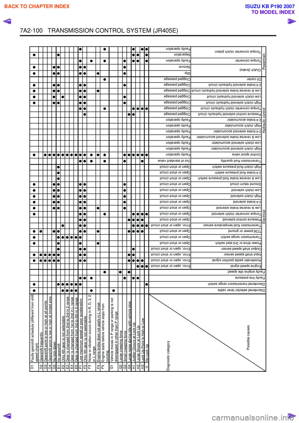
D1
Faulty gearshift schedule (different from shift
speed chart)
D2 Gearshift frequentlyD3Gearshift point is low or high at all pointsD4Gearshift point is low or high at limited areaD5No kick-downE1No gearshiftE2Only 4th gear is not selectableE3Gear is changed from 2nd to 3rd in 2 rangeE4Gear is changed from 1st to 2nd in L rangeE5Gear is changed from 3rd to 4th in 3 rangeF1Low maximum speed or poor accelerationF2Only 4th gear is not selectableF3
Noise or vibration occurs during in R, D, 3, 2
or L range
F4 Engine brake does not apply in L rangeF5
Engine stalls before vehicle stops from
running
G1
Vehicle moves in P range or parking is not
disengaged in other than P range
G2 Large creeping forceG3Small creeping forceG4Large noise during idle with vehicle stopH1Judder Occurs at Lock UpH2Large Shock at Lock UpH3Lock Up Point is High or LowI1No Lock Up
Error, open or short circuit
Error, open or short circuit
Error, open or short circuit
Error, open or short circuit
Open or short circuit
Open or short circuit
Open or short circuit
Error, open or short circuit
Open or short circuit
Open or short circuit
Open or short circuit
Open or short circuit
Open or short circuit
Open or short circuit
Open or short circuit
Open or short circuit
Open or short circuit
Open or short circuit
Out of standard value
Faulty operation
Faulty operation
Faulty operation
Faulty operation
Faulty operation
Faulty operation
Faulty operation
Clogged passage
Clogged passage
Clogged passage
Clogged passage
Clogged passage
Clogged passage
Clogged passage
Slip
Seizure
Faulty operation
Separation
Faulty operation
Engine speed signal
Accelerator pedal position signal
Input shaft speed sensor
Output shaft speed sensor
Power drive or 3rd start switch
Transmission range switch
TCM power or ground
Transmission fluid temperature sensor
Pressure control solenoid
Torque converter clutch solenoid
Low & reverse brake solenoid
2-4 brake solenoid
High clutch solenoid
Low clutch solenoid
Ground return circuit
Low & reverse brake fluid pressure switch
2-4 brake fluid pressure switch
High clutch fluid pressure switch
Transmission fluid quantity
Control spool valve
High clutch solenoid accumulator
Low clutch solenoid accumulator
Low & reverse brake solenoid accumulator
2-4 brake solenoid accumulator
High clutch accumulator
2-4 brake accumulator
Pressure control solenoid hydraulic circuit
Torque converter clutch hydraulic circuit
High clutch solenoid hydraulic circuit
Low clutch solenoid hydraulic circuit
Low & reverse brake solenoid hydraulic circuit
2-4 brake solenoid hydraulic circuit
Oil cooler
Torque converter
Diagnostic category
Possible causes
Electrical
Disordered selector lever cable
Disordered transmission range switch
Faulty line pressure
Faulty engine idle speed
Clutch (brake)
Torque converter clutch piston
Hydraulic control
Powertrain
BACK TO CHAPTER INDEX
TO MODEL INDEX
ISUZU KB P190 2007
Page 4385 of 6020
TRANSMISSION CONTROL SYSTEM (JR405E) 7A2-101
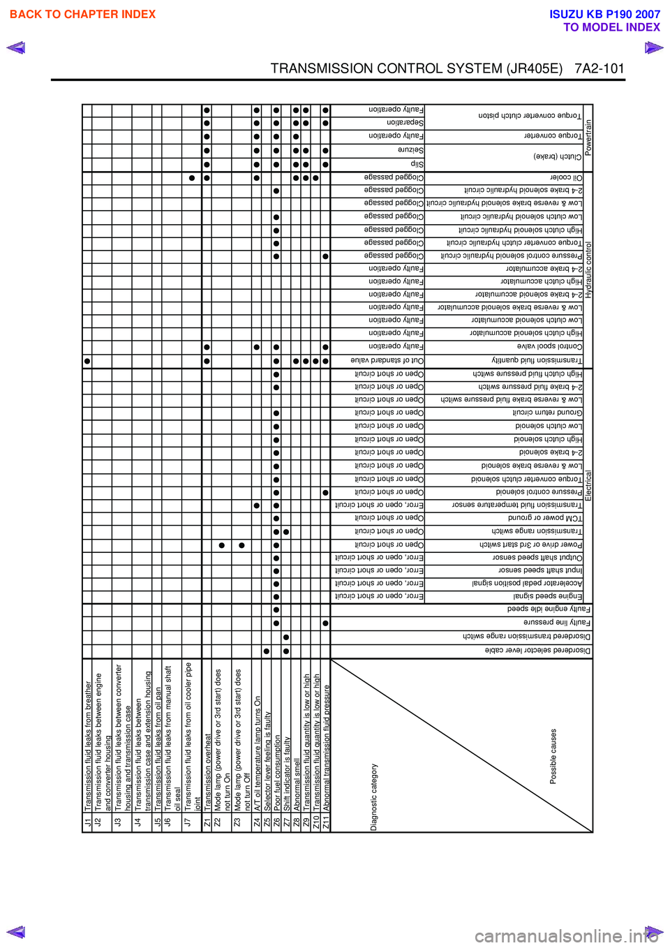
J1Transmission fluid leaks from breatherJ2
Transmission fluid leaks between engine
and converter housing
J3
Transmission fluid leaks between converter
housing and transmission case
J4
Transmission fluid leaks between
transmission case and extension housing
J5 Transmission fluid leaks from oil panJ6
Transmission fluid leaks from manual shaft
oil seal
J7
Transmission fluid leaks from oil cooler pipe
joint
Z1 Transmission overheatZ2
Mode lamp (power drive or 3rd start) does
not turn On
Z3
Mode lamp (power drive or 3rd start) does
not turn Off
Z4 A/T oil temperature lamp turns OnZ5Selector lever feeling is faultyZ6Poor fuel consumptionZ7Shift indicator is faultyZ8Abnormal smellZ9Transmission fluid quantity is low or highZ10 Transmission fluid quantity is low or highZ11Abnormal transmission fluid pressure
Error, open or short circuit
Error, open or short circuit
Error, open or short circuit
Error, open or short circuit
Open or short circuit
Open or short circuit
Open or short circuit
Error, open or short circuit
Open or short circuit
Open or short circuit
Open or short circuit
Open or short circuit
Open or short circuit
Open or short circuit
Open or short circuit
Open or short circuit
Open or short circuit
Open or short circuit
Out of standard value
Faulty operation
Faulty operation
Faulty operation
Faulty operation
Faulty operation
Faulty operation
Faulty operation
Clogged passage
Clogged passage
Clogged passage
Clogged passage
Clogged passage
Clogged passage
Clogged passage
Slip
Seizure
Faulty operation
Separation
Faulty operation
Engine speed signal
Accelerator pedal position signal
Input shaft speed sensor
Output shaft speed sensor
Power drive or 3rd start switch
Transmission range switch
TCM power or ground
Transmission fluid temperature sensor
Pressure control solenoid
Torque converter clutch solenoid
Low & reverse brake solenoid
2-4 brake solenoid
High clutch solenoid
Low clutch solenoid
Ground return circuit
Low & reverse brake fluid pressure switch
2-4 brake fluid pressure switch
High clutch fluid pressure switch
Transmission fluid quantity
Control spool valve
High clutch solenoid accumulator
Low clutch solenoid accumulator
Low & reverse brake solenoid accumulator
2-4 brake solenoid accumulator
High clutch accumulator
2-4 brake accumulator
Pressure control solenoid hydraulic circuit
Torque converter clutch hydraulic circuit
High clutch solenoid hydraulic circuit
Low clutch solenoid hydraulic circuit
Low & reverse brake solenoid hydraulic circuit
2-4 brake solenoid hydraulic circuit
Oil cooler
Torque converter
Clutch (brake)
Torque converter clutch piston
Hydraulic control
Powertrain
Diagnostic category
Possible causes
Electrical
Disordered selector lever cable
Disordered transmission range switch
Faulty line pressure
Faulty engine idle speed
BACK TO CHAPTER INDEX
TO MODEL INDEX
ISUZU KB P190 2007
Page 4400 of 6020
7A2-116 TRANSMISSION CONTROL SYSTEM (JR405E)
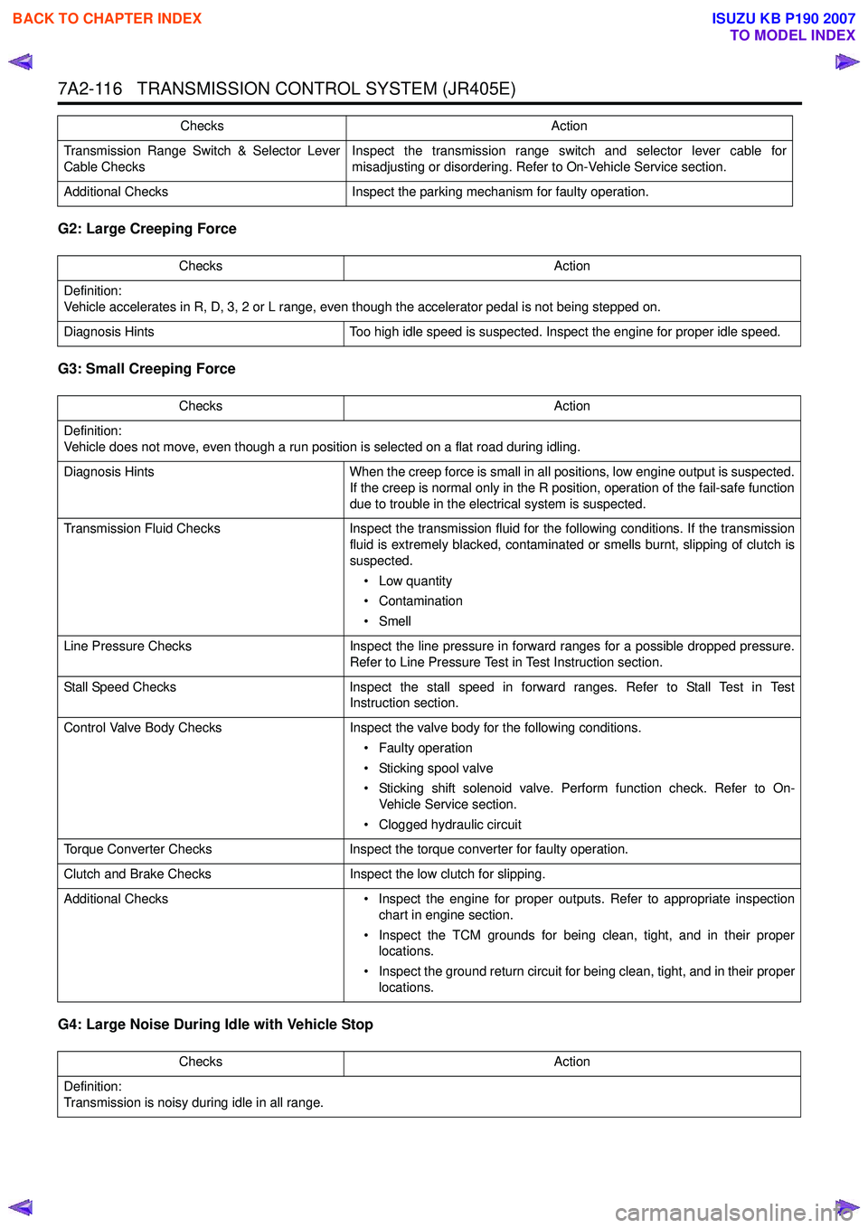
G2: Large Creeping Force
G3: Small Creeping Force
G4: Large Noise During Idle with Vehicle Stop
Transmission Range Switch & Selector Lever
Cable Checks Inspect the transmission range switch and selector lever cable for
misadjusting or disordering. Refer to On-Vehicle Service section.
Additional Checks Inspect the parking mechanism for faulty operation. Checks Action
Checks
Action
Definition:
Vehicle accelerates in R, D, 3, 2 or L range, even though the accelerator pedal is not being stepped on.
Diagnosis Hints Too high idle speed is suspected. Inspect the engine for proper idle speed.
Checks Action
Definition:
Vehicle does not move, even though a run position is selected on a flat road during idling.
Diagnosis Hints When the creep force is small in all positions, low engine output is suspected.
If the creep is normal only in the R position, operation of the fail-safe function
due to trouble in the electrical system is suspected.
Transmission Fluid Checks Inspect the transmission fluid for the following conditions. If the transmission
fluid is extremely blacked, contaminated or smells burnt, slipping of clutch is
suspected.
• Low quantity
• Contamination
•Smell
Line Pressure Checks Inspect the line pressure in forward ranges for a possible dropped pressure.
Refer to Line Pressure Test in Test Instruction section.
Stall Speed Checks Inspect the stall speed in forward ranges. Refer to Stall Test in Test
Instruction section.
Control Valve Body Checks Inspect the valve body for the following conditions.
• Faulty operation
• Sticking spool valve
• Sticking shift solenoid valve. Perform function check. Refer to On- Vehicle Service section.
• Clogged hydraulic circuit
Torque Converter Checks Inspect the torque converter for faulty operation.
Clutch and Brake Checks Inspect the low clutch for slipping.
Additional Checks • Inspect the engine for proper outputs. Refer to appropriate inspection
chart in engine section.
• Inspect the TCM grounds for being clean, tight, and in their proper locations.
• Inspect the ground return circuit for being clean, tight, and in their proper locations.
Checks Action
Definition:
Transmission is noisy during idle in all range.
BACK TO CHAPTER INDEX
TO MODEL INDEX
ISUZU KB P190 2007
Page 4424 of 6020
7A2-140 TRANSMISSION CONTROL SYSTEM (JR405E)
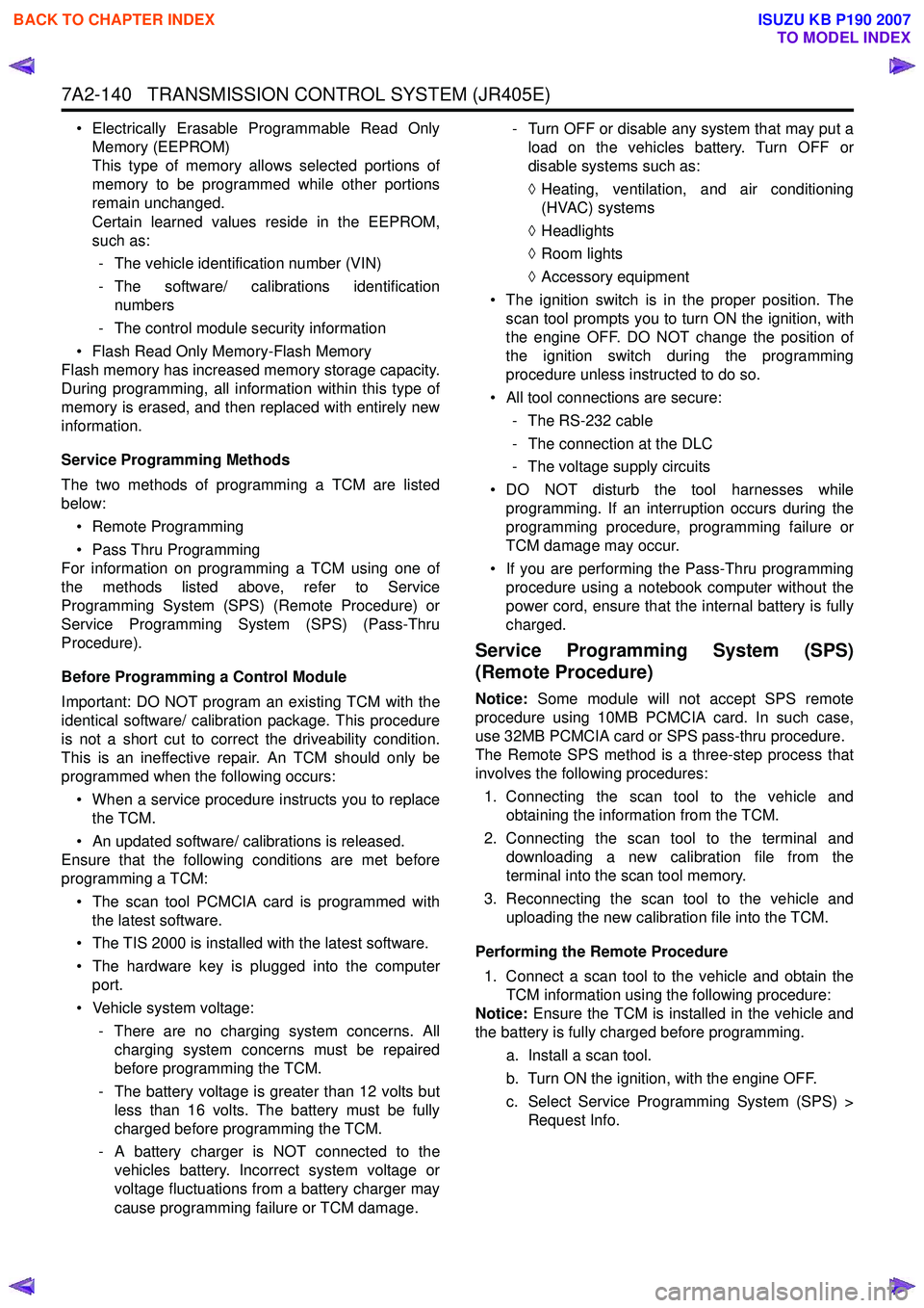
• Electrically Erasable Programmable Read OnlyMemory (EEPROM)
This type of memory allows selected portions of
memory to be programmed while other portions
remain unchanged.
Certain learned values reside in the EEPROM,
such as:
- The vehicle identification number (VIN)
- The software/ calibrations identification numbers
- The control module security information
• Flash Read Only Memory-Flash Memory
Flash memory has increased memory storage capacity.
During programming, all information within this type of
memory is erased, and then replaced with entirely new
information.
Service Programming Methods
The two methods of programming a TCM are listed
below:
• Remote Programming
• Pass Thru Programming
For information on programming a TCM using one of
the methods listed above, refer to Service
Programming System (SPS) (Remote Procedure) or
Service Programming System (SPS) (Pass-Thru
Procedure).
Before Programming a Control Module
Important: DO NOT program an existing TCM with the
identical software/ calibration package. This procedure
is not a short cut to correct the driveability condition.
This is an ineffective repair. An TCM should only be
programmed when the following occurs:
• When a service procedure instructs you to replace the TCM.
• An updated software/ calibrations is released.
Ensure that the following conditions are met before
programming a TCM:
• The scan tool PCMCIA card is programmed with the latest software.
• The TIS 2000 is installed with the latest software.
• The hardware key is plugged into the computer port.
• Vehicle system voltage:
- There are no charging system concerns. Allcharging system concerns must be repaired
before programming the TCM.
- The battery voltage is greater than 12 volts but less than 16 volts. The battery must be fully
charged before programming the TCM.
- A battery charger is NOT connected to the vehicles battery. Incorrect system voltage or
voltage fluctuations from a battery charger may
cause programming failure or TCM damage. - Turn OFF or disable any system that may put a
load on the vehicles battery. Turn OFF or
disable systems such as:
◊ Heating, ventilation, and air conditioning
(HVAC) systems
◊ Headlights
◊ Room lights
◊ Accessory equipment
• The ignition switch is in the proper position. The scan tool prompts you to turn ON the ignition, with
the engine OFF. DO NOT change the position of
the ignition switch during the programming
procedure unless instructed to do so.
• All tool connections are secure:
- The RS-232 cable
- The connection at the DLC
- The voltage supply circuits
• DO NOT disturb the tool harnesses while programming. If an interruption occurs during the
programming procedure, programming failure or
TCM damage may occur.
• If you are performing the Pass-Thru programming procedure using a notebook computer without the
power cord, ensure that the internal battery is fully
charged.
Service Programming System (SPS)
(Remote Procedure)
Notice: Some module will not accept SPS remote
procedure using 10MB PCMCIA card. In such case,
use 32MB PCMCIA card or SPS pass-thru procedure.
The Remote SPS method is a three-step process that
involves the following procedures:
1. Connecting the scan tool to the vehicle and obtaining the information from the TCM.
2. Connecting the scan tool to the terminal and downloading a new calibration file from the
terminal into the scan tool memory.
3. Reconnecting the scan tool to the vehicle and uploading the new calibration file into the TCM.
Performing the Remote Procedure 1. Connect a scan tool to the vehicle and obtain the TCM information using the following procedure:
Notice: Ensure the TCM is installed in the vehicle and
the battery is fully charged before programming.
a. Install a scan tool.
b. Turn ON the ignition, with the engine OFF.
c. Select Service Programming System (SPS) > Request Info.
BACK TO CHAPTER INDEX
TO MODEL INDEX
ISUZU KB P190 2007
Page 4428 of 6020
7A2-144 TRANSMISSION CONTROL SYSTEM (JR405E)
The JR405E automatic transmission is electrically
controlled by a transmission control module (TCM).
There are four forward speeds and one reverse speed.
This JR405E automatic transmission employs a clutch
pressure direct control system (Direct Electronic Shift
Control: DESC) using duty cycle type solenoid valves,
which ensure high shift quality. This transmission also
has a learning function and constantly checks the time
of each clutch and brake required for the shift in order
to match this time with the target value for the optimum
shift. The TCM will automatically select the most
appropriate shift points and lock-up points depending
on the accelerator pedal opening, the vehicle speed
and the vehicle load. If any trouble arises in the speed
sensor, solenoid valve, etc., the fail-safe control
function is activated to keep the running performance.
The JR405E automatic transmission consists of the
torque converter, oil pump, input shaft, out put shaft,
planetary gears and valve body. The gear train consists
of two planetary gear sets and three multiple plate
clutches in combination with two multiple plate brakes
and a one-way clutch.
Transmission Component Description
Torque Converter
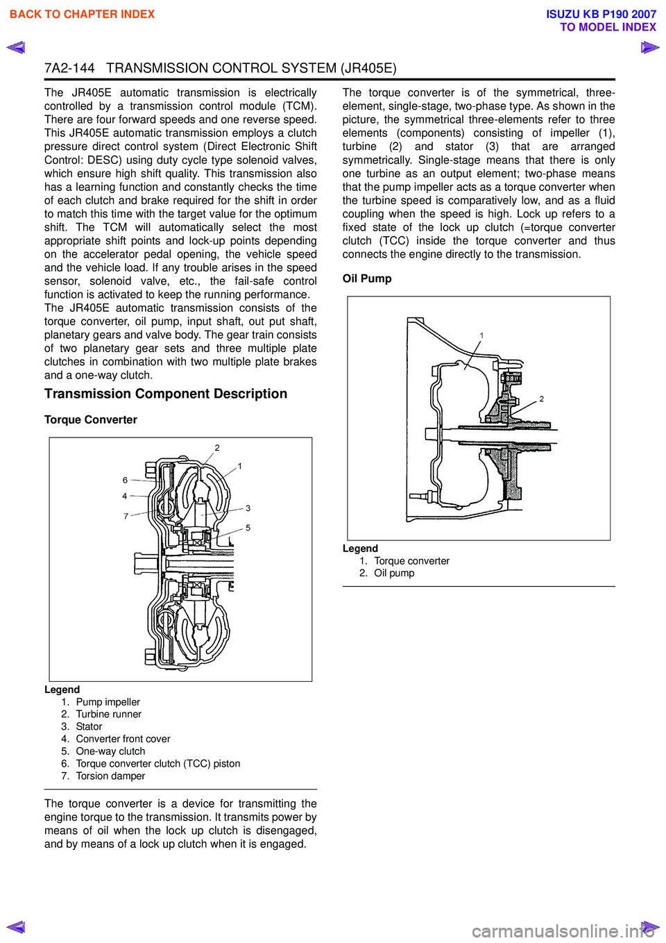
Legend
1. Pump impeller
2. Turbine runner
3. Stator
4. Converter front cover
5. One-way clutch
6. Torque converter clutch (TCC) piston
7. Torsion damper
The torque converter is a device for transmitting the
engine torque to the transmission. It transmits power by
means of oil when the lock up clutch is disengaged,
and by means of a lock up clutch when it is engaged. The torque converter is of the symmetrical, three-
element, single-stage, two-phase type. As shown in the
picture, the symmetrical three-elements refer to three
elements (components) consisting of impeller (1),
turbine (2) and stator (3) that are arranged
symmetrically. Single-stage means that there is only
one turbine as an output element; two-phase means
that the pump impeller acts as a torque converter when
the turbine speed is comparatively low, and as a fluid
coupling when the speed is high. Lock up refers to a
fixed state of the lock up clutch (=torque converter
clutch (TCC) inside the torque converter and thus
connects the engine directly to the transmission.
Oil Pump
Legend 1. Torque converter
2. Oil pump
BACK TO CHAPTER INDEX
TO MODEL INDEX
ISUZU KB P190 2007
Page 4878 of 6020
7D1-4 TRANSFER CONTROL SYSTEM
Summary of transfer control system
The transfer control system switches between the 2-wheel
drive (2H), 4-wheel drive high-speed (4H), 4-wheel drive low-
speed (4L), and neutral positions electrically when the driver
operates the switches.
This system has following functions.
1. Connection or disconnection of drive force distribution to the
front wheel front shaft (axle shaft). (The drive force
distribution to the front propeller is connected o
r
disconnected with the motor actuator.)
2. Try to repeat the connection or disconnection of the front wheel drive function as described above.
3. Option: Shift on the fly type only.
Instruction of connection or disconnection of the drive force transmission between the front wheel axle (axle shaft) and
front wheel. (The motor actuator connects or disconnects
the left front wheel and front wheel axle (axle shaft).)
4. Shifting of auxiliary transmission gears, connection o
r
disconnection of wheel and engine drive force (4H, 4L,
neutral).
5. Operation of the indicator on the instrument panel.
6. Transmission of the position signal to other controllers.
BACK TO CHAPTER INDEX
TO MODEL INDEX
ISUZU KB P190 2007
Page 4938 of 6020

PAGE
SECTION 8
ELECTRICAL - B ODY AND CH ASSIS
TA BLE OF CONTENTS
ELE CTR ICAL -BO DY AND CH ASSIS 8 -1
TO MODEL INDEX
S ectio n 8 A E le ctr ic al- B ody a n d C hassis .....................................................................5 032
S ectio n 8 B C ru is e C ontr o l S yste m ...............................................................................5 666
Section 8 CCruise Control-HFV6...................................................................................5 673
BACK TO MAIN INDEXISUZU KB P190 2007
Page 4939 of 6020
ELECTRICAL-BODY AND CHASSIS 8A-1
SECTION 8A
ELECTRICAL-BODY AND CHASSIS
TABLE OF CONTENTS
PAGE
General Information ........................................................................................................... .........8A- 4
Notes for Working on Electrical Items .......................................................................................8A - 5
Symbols and A bbreviations ..................................................................................................... ..8A- 11
Symbols ....................................................................................................................... ................ 8A- 11
Abbreviations ................................................................................................................. ..............8A- 12
Parts for Electri cal Circuit .................................................................................................. ........8A- 13
Wiring ........................................................................................................................ ...................8A- 13
Fuse .......................................................................................................................... ....................8A- 15
Fusible Link .................................................................................................................. ...............8A- 15
Relay ......................................................................................................................... ....................8A- 16
Diode ......................................................................................................................... ...................8A- 17
Connector ..................................................................................................................... ...............8A- 18
Battery ....................................................................................................................... ...................8A- 19
Reading the Circuit Diagram ................................................................................................... ...8A- 22
Parts Location ................................................................................................................ ..............8A- 22
Circuit Diagram ............................................................................................................... .............8A- 23
Connector List ................................................................................................................ .............8A- 23
Main Data and Specifications .................................................................................................. ...8A- 24
Bulb Specifications ........................................................................................................... ..........8A- 24
Relay and Fuse ................................................................................................................ ............8A- 26
Relay and Fuse Box Location (RHD) .........................................................................................8A- 26
Relay and Fuse Box Location (LHD) ..........................................................................................8A- 27
Relay Location ................................................................................................................ .............8A- 28
Fuse and Slow Blow Fuse Location ...........................................................................................8A- 31
Fuse Location ................................................................................................................. .............8A- 33
Diode Location ................................................................................................................ .............8A- 34
Fuse Block Circuit (C24SE) .................................................................................................... ....8A- 35/36
Fuse Block Circuit (HFV6) ...................................................................................................... .....8A- 37
BACK TO CHAPTER INDEX
TO MODEL INDEX
ISUZU KB P190 2007