2007 ISUZU KB P190 Electrical
[x] Cancel search: ElectricalPage 4317 of 6020
TRANSMISSION CONTROL SYSTEM (JR405E) 7A2-33
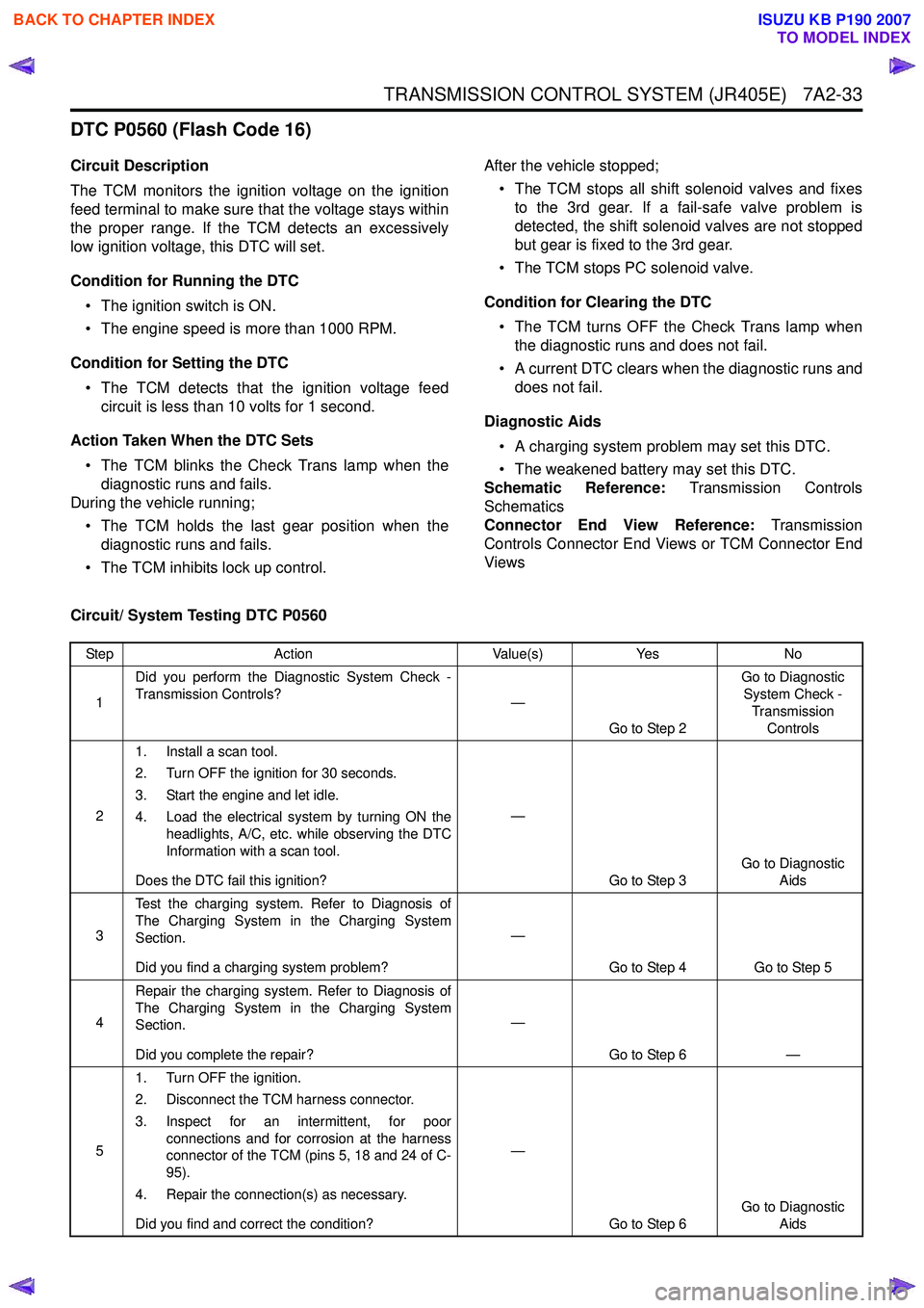
DTC P0560 (Flash Code 16)
Circuit Description
The TCM monitors the ignition voltage on the ignition
feed terminal to make sure that the voltage stays within
the proper range. If the TCM detects an excessively
low ignition voltage, this DTC will set.
Condition for Running the DTC • The ignition switch is ON.
• The engine speed is more than 1000 RPM.
Condition for Setting the DTC • The TCM detects that the ignition voltage feed circuit is less than 10 volts for 1 second.
Action Taken When the DTC Sets • The TCM blinks the Check Trans lamp when the diagnostic runs and fails.
During the vehicle running;
• The TCM holds the last gear position when the diagnostic runs and fails.
• The TCM inhibits lock up control. After the vehicle stopped;
• The TCM stops all shift solenoid valves and fixes to the 3rd gear. If a fail-safe valve problem is
detected, the shift solenoid valves are not stopped
but gear is fixed to the 3rd gear.
• The TCM stops PC solenoid valve.
Condition for Clearing the DTC • The TCM turns OFF the Check Trans lamp when the diagnostic runs and does not fail.
• A current DTC clears when the diagnostic runs and does not fail.
Diagnostic Aids • A charging system problem may set this DTC.
• The weakened battery may set this DTC.
Schematic Reference: Transmission Controls
Schematics
Connector End View Reference: Transmission
Controls Connector End Views or TCM Connector End
Views
Circuit/ System Testing DTC P0560
Step Action Value(s)Yes No
1 Did you perform the Diagnostic System Check -
Transmission Controls? —
Go to Step 2 Go to Diagnostic
System Check -
Transmission Controls
2 1. Install a scan tool.
2. Turn OFF the ignition for 30 seconds.
3. Start the engine and let idle.
4. Load the electrical system by turning ON the headlights, A/C, etc. while observing the DTC
Information with a scan tool.
Does the DTC fail this ignition? —
Go to Step 3 Go to Diagnostic
Aids
3 Test the charging system. Refer to Diagnosis of
The Charging System in the Charging System
Section.
Did you find a charging system problem? —
Go to Step 4 Go to Step 5
4 Repair the charging system. Refer to Diagnosis of
The Charging System in the Charging System
Section.
Did you complete the repair? —
Go to Step 6 —
5 1. Turn OFF the ignition.
2. Disconnect the TCM harness connector.
3. Inspect for an intermittent, for poor connections and for corrosion at the harness
connector of the TCM (pins 5, 18 and 24 of C-
95).
4. Repair the connection(s) as necessary.
Did you find and correct the condition? —
Go to Step 6 Go to Diagnostic
Aids
BACK TO CHAPTER INDEX
TO MODEL INDEX
ISUZU KB P190 2007
Page 4318 of 6020
7A2-34 TRANSMISSION CONTROL SYSTEM (JR405E)
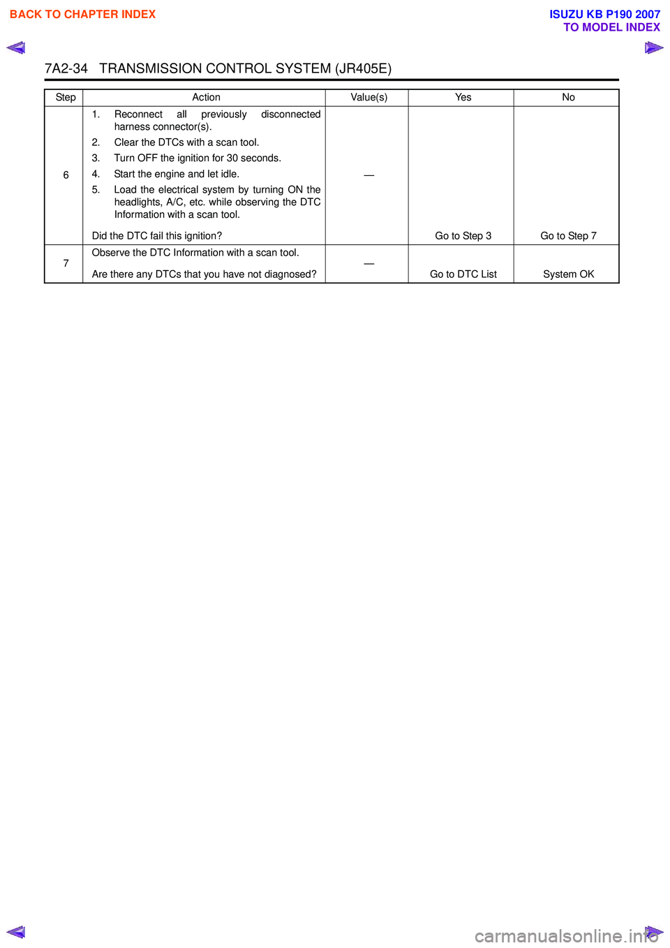
61. Reconnect all previously disconnected
harness connector(s).
2. Clear the DTCs with a scan tool.
3. Turn OFF the ignition for 30 seconds.
4. Start the engine and let idle.
5. Load the electrical system by turning ON the headlights, A/C, etc. while observing the DTC
Information with a scan tool.
Did the DTC fail this ignition? —
Go to Step 3 Go to Step 7
7 Observe the DTC Information with a scan tool.
Are there any DTCs that you have not diagnosed? —
Go to DTC List System OK
Step
Action Value(s)Yes No
BACK TO CHAPTER INDEX
TO MODEL INDEX
ISUZU KB P190 2007
Page 4337 of 6020
TRANSMISSION CONTROL SYSTEM (JR405E) 7A2-53
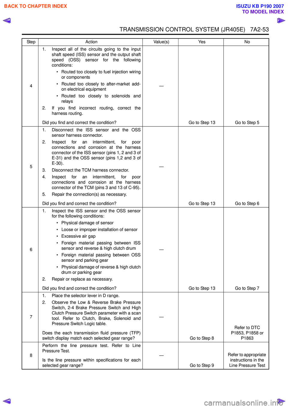
41. Inspect all of the circuits going to the input
shaft speed (ISS) sensor and the output shaft
speed (OSS) sensor for the following
conditions:
• Routed too closely to fuel injection wiring or components
• Routed too closely to after-market add- on electrical equipment
• Routed too closely to solenoids and relays
2. If you find incorrect routing, correct the harness routing.
Did you find and correct the condition? —
Go to Step 13 Go to Step 5
5 1. Disconnect the ISS sensor and the OSS
sensor harness connector.
2. Inspect for an intermittent, for poor connections and corrosion at the harness
connector of the ISS sensor (pins 1, 2 and 3 of
E-31) and the OSS sensor (pins 1,2 and 3 of
E-30).
3. Disconnect the TCM harness connector.
4. Inspect for an intermittent, for poor connections and corrosion at the harness
connector of the TCM (pins 3 and 13 of C-95).
5. Repair the connection(s) as necessary.
Did you find and correct the condition? —
Go to Step 13 Go to Step 6
6 1. Inspect the ISS sensor and the OSS sensor
for the following conditions:
• Physical damage of sensor
• Loose or improper installation of sensor
• Excessive air gap
• Foreign material passing between ISS sensor and reverse & high clutch drum
• Foreign material passing between OSS sensor and parking gear
• Physical damage of reverse & high clutch drum or parking gear
2. Repair or replace as necessary.
Did you find and correct the condition? —
Go to Step 13 Go to Step 7
7 1. Place the selector lever in D range.
2. Observe the Low & Reverse Brake Pressure Switch, 2-4 Brake Pressure Switch and High
Clutch Pressure Switch parameter with a scan
tool. Refer to Clutch, Brake, Solenoid and
Pressure Switch Logic table.
Does the each transmission fluid pressure (TFP)
switch display match each selected gear range? —
Go to Step 8 Refer to DTC
P1853, P1858 or P1863
8 Perform the line pressure test. Refer to Line
Pressure Test.
Is the line pressure within specifications for each
selected gear range? —
Go to Step 9 Refer to appropriate
instructions in the
Line Pressure Test
Step
Action Value(s)Yes No
BACK TO CHAPTER INDEX
TO MODEL INDEX
ISUZU KB P190 2007
Page 4376 of 6020
7A2-92 TRANSMISSION CONTROL SYSTEM (JR405E)
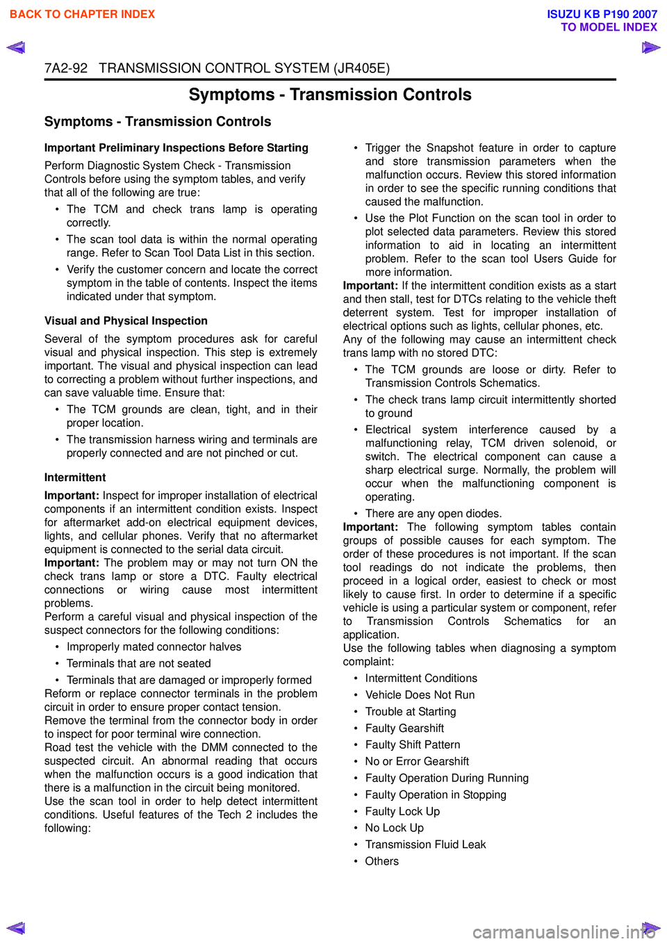
Symptoms - Transmission Controls
Symptoms - Transmission Controls
Important Preliminary Inspections Before Starting
Perform Diagnostic System Check - Transmission
Controls before using the symptom tables, and verify
that all of the following are true:
• The TCM and check trans lamp is operating correctly.
• The scan tool data is within the normal operating range. Refer to Scan Tool Data List in this section.
• Verify the customer concern and locate the correct symptom in the table of contents. Inspect the items
indicated under that symptom.
Visual and Physical Inspection
Several of the symptom procedures ask for careful
visual and physical inspection. This step is extremely
important. The visual and physical inspection can lead
to correcting a problem without further inspections, and
can save valuable time. Ensure that:
• The TCM grounds are clean, tight, and in their proper location.
• The transmission harness wiring and terminals are properly connected and are not pinched or cut.
Intermittent
Important: Inspect for improper installation of electrical
components if an intermittent condition exists. Inspect
for aftermarket add-on electrical equipment devices,
lights, and cellular phones. Verify that no aftermarket
equipment is connected to the serial data circuit.
Important: The problem may or may not turn ON the
check trans lamp or store a DTC. Faulty electrical
connections or wiring cause most intermittent
problems.
Perform a careful visual and physical inspection of the
suspect connectors for the following conditions:
• Improperly mated connector halves
• Terminals that are not seated
• Terminals that are damaged or improperly formed
Reform or replace connector terminals in the problem
circuit in order to ensure proper contact tension.
Remove the terminal from the connector body in order
to inspect for poor terminal wire connection.
Road test the vehicle with the DMM connected to the
suspected circuit. An abnormal reading that occurs
when the malfunction occurs is a good indication that
there is a malfunction in the circuit being monitored.
Use the scan tool in order to help detect intermittent
conditions. Useful features of the Tech 2 includes the
following: • Trigger the Snapshot feature in order to capture
and store transmission parameters when the
malfunction occurs. Review this stored information
in order to see the specific running conditions that
caused the malfunction.
• Use the Plot Function on the scan tool in order to plot selected data parameters. Review this stored
information to aid in locating an intermittent
problem. Refer to the scan tool Users Guide for
more information.
Important: If the intermittent condition exists as a start
and then stall, test for DTCs relating to the vehicle theft
deterrent system. Test for improper installation of
electrical options such as lights, cellular phones, etc.
Any of the following may cause an intermittent check
trans lamp with no stored DTC:
• The TCM grounds are loose or dirty. Refer to Transmission Controls Schematics.
• The check trans lamp circuit intermittently shorted to ground
• Electrical system interference caused by a malfunctioning relay, TCM driven solenoid, or
switch. The electrical component can cause a
sharp electrical surge. Normally, the problem will
occur when the malfunctioning component is
operating.
• There are any open diodes.
Important: The following symptom tables contain
groups of possible causes for each symptom. The
order of these procedures is not important. If the scan
tool readings do not indicate the problems, then
proceed in a logical order, easiest to check or most
likely to cause first. In order to determine if a specific
vehicle is using a particular system or component, refer
to Transmission Controls Schematics for an
application.
Use the following tables when diagnosing a symptom
complaint:
• Intermittent Conditions
• Vehicle Does Not Run
• Trouble at Starting
• Faulty Gearshift
• Faulty Shift Pattern
• No or Error Gearshift
• Faulty Operation During Running
• Faulty Operation in Stopping
• Faulty Lock Up
• No Lock Up
• Transmission Fluid Leak
•Others
BACK TO CHAPTER INDEX
TO MODEL INDEX
ISUZU KB P190 2007
Page 4377 of 6020
TRANSMISSION CONTROL SYSTEM (JR405E) 7A2-93
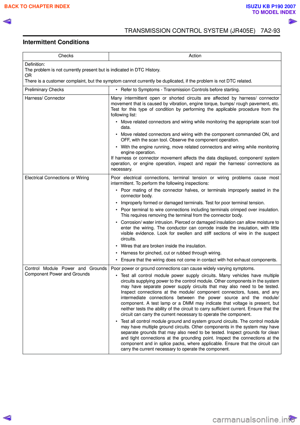
Intermittent Conditions
ChecksAction
Definition:
The problem is not currently present but is indicated in DTC History.
OR
There is a customer complaint, but the symptom cannot currently be duplicated, if the problem is not DTC related.
Preliminary Checks • Refer to Symptoms - Transmission Controls before starting.
Harness/ Connector Many intermittent open or shorted circuits are affected by harness/ connector
movement that is caused by vibration, engine torque, bumps/ rough pavement, etc.
Test for this type of condition by performing the applicable procedure from the
following list:
• Move related connectors and wiring while monitoring the appropriate scan tool data.
• Move related connectors and wiring with the component commanded ON, and OFF, with the scan tool. Observe the component operation.
• With the engine running, move related connectors and wiring while monitoring engine operation.
If harness or connector movement affects the data displayed, component/ system
operation, or engine operation, inspect and repair the harness/ connections as
necessary.
Electrical Connections or Wiring Poor electrical connections, terminal tension or wiring problems cause most intermittent. To perform the following inspections:
• Poor mating of the connector halves, or terminals improperly seated in the connector body.
• Improperly formed or damaged terminals. Test for poor terminal tension.
• Poor terminal to wire connections including terminals crimped over insulation. This requires removing the terminal from the connector body.
• Corrosion/ water intrusion. Pierced or damaged insulation can allow moisture to enter the wiring. The conductor can corrode inside the insulation, with little
visible evidence. Look for swollen and stiff sections of wire in the suspect
circuits.
• Wires that are broken inside the insulation.
• Harness for pinched, cut or rubbed through wiring.
• Ensure that the wiring does not come in contact with hot exhaust components.
Control Module Power and Grounds
Component Power and Grounds Poor power or ground connections can cause widely varying symptoms.
• Test all control module power supply circuits. Many vehicles have multiple circuits supplying power to the control module. Other components in the system
may have separate power supply circuits that may also need to be tested.
Inspect connections at the module/ component connectors, fuses, and any
intermediate connections between the power source and the module/
component. A test lamp or a DMM may indicate that voltage is present, but
neither tests the ability of the circuit to carry sufficient current. Ensure that the
circuit can carry the current necessary to operate the component.
• Test all control module ground and system ground circuits. The control module may have multiple ground circuits. Other components in the system may have
separate grounds that may also need to be tested. Inspect grounds for clean
and tight connections at the grounding point. Inspect the connections at the
component and in splice packs, where applicable. Ensure that the circuit can
carry the current necessary to operate the component.
BACK TO CHAPTER INDEX
TO MODEL INDEX
ISUZU KB P190 2007
Page 4378 of 6020
7A2-94 TRANSMISSION CONTROL SYSTEM (JR405E)
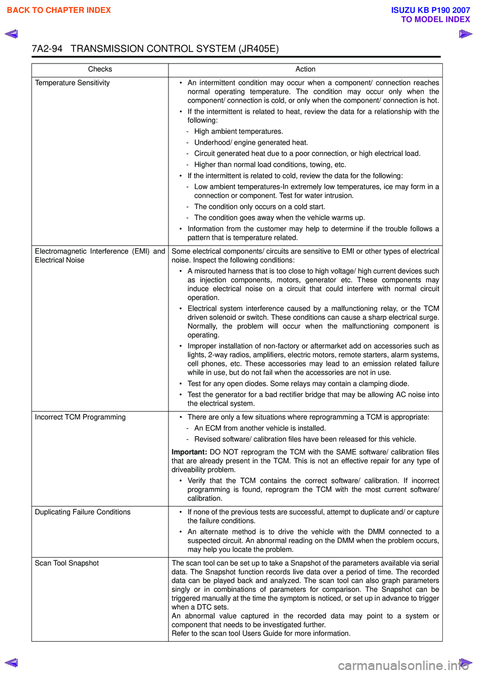
Temperature Sensitivity• An intermittent condition may occur when a component/ connection reaches
normal operating temperature. The condition may occur only when the
component/ connection is cold, or only when the component/ connection is hot.
• If the intermittent is related to heat, review the data for a relationship with the following:
- High ambient temperatures.
- Underhood/ engine generated heat.
- Circuit generated heat due to a poor connection, or high electrical load.
- Higher than normal load conditions, towing, etc.
• If the intermittent is related to cold, review the data for the following: - Low ambient temperatures-In extremely low temperatures, ice may form in a connection or component. Test for water intrusion.
- The condition only occurs on a cold start.
- The condition goes away when the vehicle warms up.
• Information from the customer may help to determine if the trouble follows a pattern that is temperature related.
Electromagnetic Interference (EMI) and
Electrical Noise Some electrical components/ circuits are sensitive to EMI or other types of electrical
noise. Inspect the following conditions:
• A misrouted harness that is too close to high voltage/ high current devices such as injection components, motors, generator etc. These components may
induce electrical noise on a circuit that could interfere with normal circuit
operation.
• Electrical system interference caused by a malfunctioning relay, or the TCM driven solenoid or switch. These conditions can cause a sharp electrical surge.
Normally, the problem will occur when the malfunctioning component is
operating.
• Improper installation of non-factory or aftermarket add on accessories such as lights, 2-way radios, amplifiers, electric motors, remote starters, alarm systems,
cell phones, etc. These accessories may lead to an emission related failure
while in use, but do not fail when the accessories are not in use.
• Test for any open diodes. Some relays may contain a clamping diode.
• Test the generator for a bad rectifier bridge that may be allowing AC noise into the electrical system.
Incorrect TCM Programming • There are only a few situations where reprogramming a TCM is appropriate:
- An ECM from another vehicle is installed.
- Revised software/ calibration files have been released for this vehicle.
Important: DO NOT reprogram the TCM with the SAME software/ calibration files
that are already present in the TCM. This is not an effective repair for any type of
driveability problem.
• Verify that the TCM contains the correct software/ calibration. If incorrect programming is found, reprogram the TCM with the most current software/
calibration.
Duplicating Failure Conditions • If none of the previous tests are successful, attempt to duplicate and/ or capture
the failure conditions.
• An alternate method is to drive the vehicle with the DMM connected to a suspected circuit. An abnormal reading on the DMM when the problem occurs,
may help you locate the problem.
Scan Tool Snapshot The scan tool can be set up to take a Snapshot of the parameters available via serial
data. The Snapshot function records live data over a period of time. The recorded
data can be played back and analyzed. The scan tool can also graph parameters
singly or in combinations of parameters for comparison. The Snapshot can be
triggered manually at the time the symptom is noticed, or set up in advance to trigger
when a DTC sets.
An abnormal value captured in the recorded data may point to a system or
component that needs to be investigated further.
Refer to the scan tool Users Guide for more information.
Checks
Action
BACK TO CHAPTER INDEX
TO MODEL INDEX
ISUZU KB P190 2007
Page 4382 of 6020
7A2-98 TRANSMISSION CONTROL SYSTEM (JR405E)
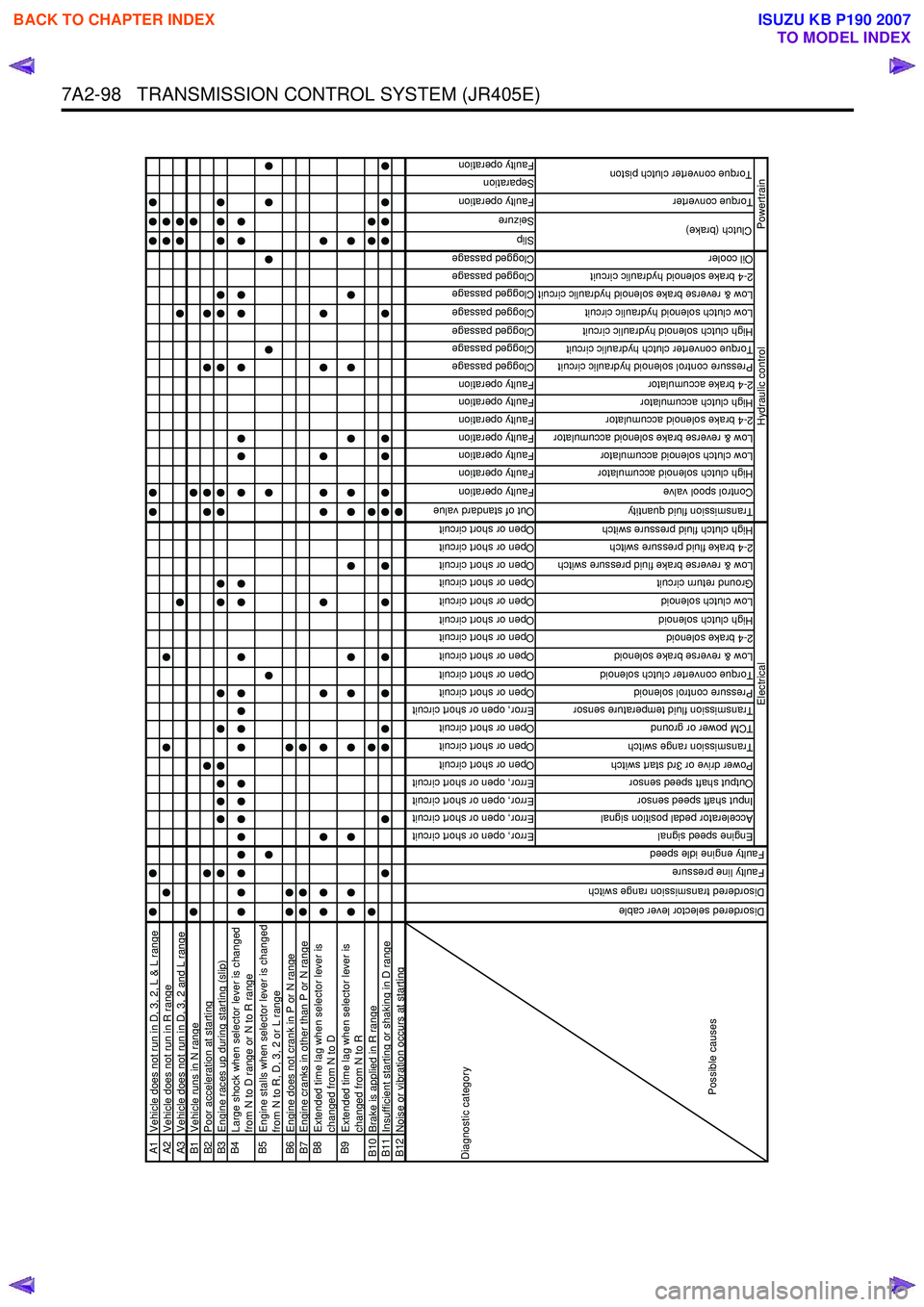
A1Vehicle does not run in D, 3, 2, L & L rangeA2Vehicle does not run in R rangeA3Vehicle does not run in D, 3, 2 and L rangeB1Vehicle runs in N rangeB2Poor acceleration at startingB3Engine races up during starting (slip)B4
Large shock when selector lever is changed
from N to D range or N to R range
B5
Engine stalls when selector lever is changed
from N to R, D, 3, 2 or L range
B6 Engine does not crank in P or N rangeB7Engine cranks in other than P or N rangeB8
Extended time lag when selector lever is
changed from N to D
B9
Extended time lag when selector lever is
changed from N to R
B10 Brake is applied in R rangeB11Insufficient starting or shaking in D rangeB12Noise or vibration occurs at starting
Error, open or short circuit
Error, open or short circuit
Error, open or short circuit
Error, open or short circuit
Open or short circuit
Open or short circuit
Open or short circuit
Error, open or short circuit
Open or short circuit
Open or short circuit
Open or short circuit
Open or short circuit
Open or short circuit
Open or short circuit
Open or short circuit
Open or short circuit
Open or short circuit
Open or short circuit
Out of standard value
Faulty operation
Faulty operation
Faulty operation
Faulty operation
Faulty operation
Faulty operation
Faulty operation
Clogged passage
Clogged passage
Clogged passage
Clogged passage
Clogged passage
Clogged passage
Clogged passage
Slip
Seizure
Faulty operation
Separation
Faulty operation
Engine speed signal
Accelerator pedal position signal
Input shaft speed sensor
Output shaft speed sensor
Power drive or 3rd start switch
Transmission range switch
TCM power or ground
Transmission fluid temperature sensor
Pressure control solenoid
Torque converter clutch solenoid
Low & reverse brake solenoid
2-4 brake solenoid
High clutch solenoid
Low clutch solenoid
Ground return circuit
Low & reverse brake fluid pressure switch
2-4 brake fluid pressure switch
High clutch fluid pressure switch
Transmission fluid quantity
Control spool valve
High clutch solenoid accumulator
Low clutch solenoid accumulator
Low & reverse brake solenoid accumulator
2-4 brake solenoid accumulator
High clutch accumulator
2-4 brake accumulator
Pressure control solenoid hydraulic circuit
Torque converter clutch hydraulic circuit
High clutch solenoid hydraulic circuit
Low clutch solenoid hydraulic circuit
Low & reverse brake solenoid hydraulic circuit
2-4 brake solenoid hydraulic circuit
Oil cooler
Torque converter
Diagnostic category
Possible causes
Electrical
Disordered selector lever cable
Disordered transmission range switch
Faulty line pressure
Faulty engine idle speed
Clutch (brake)
Torque converter clutch piston
Hydraulic control
Powertrain
BACK TO CHAPTER INDEX
TO MODEL INDEX
ISUZU KB P190 2007
Page 4383 of 6020
TRANSMISSION CONTROL SYSTEM (JR405E) 7A2-99
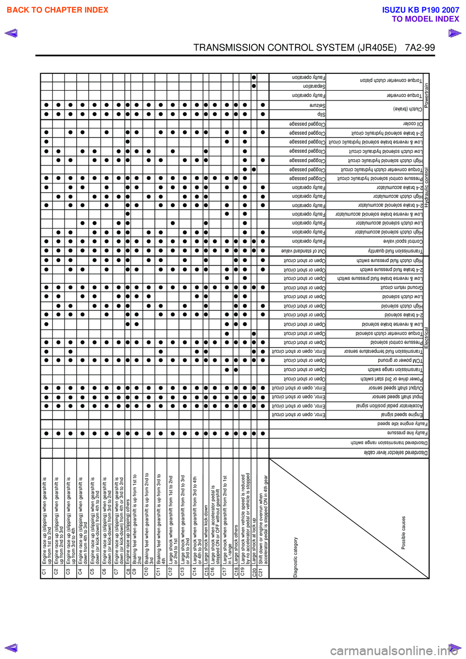
C1
Engine race up (slipping) when gearshift is
up from 1st to 2nd
C2
Engine race up (slipping) when gearshift is
up from 2nd to 3rd
C3
Engine race up (slipping) when gearshift is
up from 3rd to 4th
C4
Engine race up (slipping) when gearshift is
down from 4th to 3rd
C5
Engine race up (slipping) when gearshift is
down (or kick-down) from 4th to 2nd
C6
Engine race up (slipping) when gearshift is
down (or kick-down) from 3rd to 2nd
C7
Engine race up (slipping) when gearshift is
down (or kick-down) from 4th or 3rd to 2nd
C8 Engine race up (slipping) othersC9
Braking feel when gearshift is up from 1st to
2nd
C10
Braking feel when gearshift is up from 2nd to
3rd
C11
Braking feel when gearshift is up from 3rd to
4th
C12
Large shock when gearshift from 1st to 2nd
or 2nd to 1st
C13
Large shock when gearshift from 2nd to 3rd
or 3rd to 2nd
C14
Large shock when gearshift from 3rd to 4th
or 4th to 3rd
C15 Large shock when kick-downC16
Large shock when accelerator pedal is
stepped ON or OFF without gearshift
C17
Large shock when gearshift from 2nd to 1st
in L range
C18 Large shock othersC19
Large shock when vehicle speed is reduced
by no accelerator pedal or vehicle is stopped
C20 Large shock at lock upC21
Shift down or engine overrun when
accelerator pedal is stepped ON in 4th gear
Error, open or short circuit
Error, open or short circuit
Error, open or short circuit
Error, open or short circuit
Open or short circuit
Open or short circuit
Open or short circuit
Error, open or short circuit
Open or short circuit
Open or short circuit
Open or short circuit
Open or short circuit
Open or short circuit
Open or short circuit
Open or short circuit
Open or short circuit
Open or short circuit
Open or short circuit
Out of standard value
Faulty operation
Faulty operation
Faulty operation
Faulty operation
Faulty operation
Faulty operation
Faulty operation
Clogged passage
Clogged passage
Clogged passage
Clogged passage
Clogged passage
Clogged passage
Clogged passage
Slip
Seizure
Faulty operation
Separation
Faulty operation
Engine speed signal
Accelerator pedal position signal
Input shaft speed sensor
Output shaft speed sensor
Power drive or 3rd start switch
Transmission range switch
TCM power or ground
Transmission fluid temperature sensor
Pressure control solenoid
Torque converter clutch solenoid
Low & reverse brake solenoid
2-4 brake solenoid
High clutch solenoid
Low clutch solenoid
Ground return circuit
Low & reverse brake fluid pressure switch
2-4 brake fluid pressure switch
High clutch fluid pressure switch
Transmission fluid quantity
Control spool valve
High clutch solenoid accumulator
Low clutch solenoid accumulator
Low & reverse brake solenoid accumulator
2-4 brake solenoid accumulator
High clutch accumulator
2-4 brake accumulator
Pressure control solenoid hydraulic circuit
Torque converter clutch hydraulic circuit
High clutch solenoid hydraulic circuit
Low clutch solenoid hydraulic circuit
Low & reverse brake solenoid hydraulic circuit
2-4 brake solenoid hydraulic circuit
Oil cooler
Torque converter
Clutch (brake)
Torque converter clutch piston
Hydraulic control
Powertrain
Diagnostic category
Possible causes
Electrical
Disordered selector lever cable
Disordered transmission range switch
Faulty line pressure
Faulty engine idle speed
BACK TO CHAPTER INDEX
TO MODEL INDEX
ISUZU KB P190 2007