2007 ISUZU KB P190 Electrical
[x] Cancel search: ElectricalPage 4079 of 6020
TRANSMISSION CONTROL SYSTEM (AW30–40LE) 7A2-113
(2) All of the following conditions are met.
• Device Control is not operating.
• Disable Normal Communication is receiving
enable.
• DTC Clear is not operating.
The following condition at ignition “OFF” form “ON” is
detected seven times in total in 1 cycle.
• Receiving BUS “OFF” information from CAN
controller.
Action Taken When The DTC Set
• Throttle judgment on torque reduction control, line
pressure control at stationary status, line pressure
reduction control at gear change and line pressure
reduction control at garage. (Throttle opening 100%)
• Line pressure FULL output.
• Throttle judgment on gear change control. (Throttle
opening 0%)
• No line pressure reduction control at gear change.
• No torque reduction control.
• No squat control.
• No slope control.
• No L-up control.
• Control Engine rpm at 7000rpm. (No inertia
calculation)
• Control actual torque at MAX.
• Control driver torque at MAX.
• Control engine coolant temperature at 80 °C (176 °F).
• No coast control.
• No 3rd Start mode control.
• No line pressure reduction control at garage.
• No output revolution sensor failure detection.
• No input revolution sensor failure detection.
• No selector position switch failure detection.
• No oil temperature sensor failure detection.
• No T/F Hi-Low SW failure detection.
• No speed mater signal failure detection.
• No throttle signal failure detection.
• No Engine torque signal failure detection.
• No engine coolant temperature signal failure
detection.
• No Engine revolution signal failure detection.
• No shift solenoid functional failure detection.
• No L-up solenoid functional failure detection.
• No DTC U2105 failure detection.
• Cancel engine rpm condition of prerequisite of suppl
y
voltage failure detection.
• Control vehicle speed of speed meter at 0km/h.
• No torque reduction at stall.
• No cruise control.
• No warm up control.
• DTC stored.
• Check Trans “ON”.
• MIL request “ON”. (EURO 4 only)
Conditions For Clearing The DTC
• The DTC can be cleared from the TCM history by
using a scan tool.
• The DTC will be cleared from history when the vehicle has achieved 40 warm-up cycles without a
failure reported.
•
After more than 1 second has elapsed after the
ignition key has been turned “ON”, short between
No.11 and No.4 (ground) of DLC (Data Link
Connector). Then, after 1 second, but within 6
seconds, discontinue shorting.
Diagnostic Aids
• Inspect the wiring for poor electrical connection at the
TCM. Look for possible bent, backed out, deformed
or damaged terminals. Check for weak terminal
tension as well. Also check for a chafed wire that
could short to bare metal or other wiring. Inspect for a
broken wire inside the insulation.
• W hen diagnosing for a possible intermittent short o
r
open condition, move the wiring harness while
observing test equipment for a change.
• Inspect the wiring for EMI (Electro-Magnetic
Interference). Check that all wires are properly routed
away from coil, and generator. Also check fo
r
improperly installed electrical options. W hen this test
is performed, turn “OFF” on electronic auto parts
switches to improperly for a noise preventing.
BACK TO CHAPTER INDEX
TO MODEL INDEX
ISUZU KB P190 2007
Page 4083 of 6020
TRANSMISSION CONTROL SYSTEM (AW30–40LE) 7A2-117
(3) All of the following conditions are met.
• Device Control is not operating.
• Disable Normal Communication is receiving
enable.
• DTC Clear is not operating.
(4) DTC U2104 is not detecting failure or not deciding failure.
Condition For Setting The DTC
Detection standard is met for 2.5 second continuously.
Detection standard:
If one or more ID sent from Engine Control Module
(ECM) is not completed receiving for 2 basic cycles
since last receiving completion.
Action Taken When The DTC Sets
• Throttle judgment on torque reduction control, line
pressure control at stationary status, line pressure
reduction control at gear change and line pressure
reduction control at garage. (Throttle opening 100%)
• Line pressure FULL output.
• Throttle judgment on gear change control (Throttle
opening 0%).
• No line pressure reduction control at gear change.
• No torque reduction control.
• No squat control.
• No slope control (keep mode).
• No L-up control.
• Control Engine rpm at 7000rpm (No inertia
calculation).
• Control actual torque at MAX.
• Control driver torque at MAX.
• Control engine coolant temperature at 80 °C (176 °F).
• No coast control.
• No 3rd Start mode control.
• No line pressure reduction control at garage.
• No output revolution sensor failure detection.
• No C-0 rev sensor failure detection.
• No selector position switch failure detection.
• No oil temperature sensor failure detection.
• No T/F Hi-Low SW failure detection (Execute T/F
judgment using only T/F-SW ).
• No speed mater signal failure detection.
• No throttle signal failure detection.
• No Engine torque signal failure detection.
• No engine coolant temperature signal failure
detection.
• No Engine revolution signal failure detection.
• No shift solenoid functional failure detection.
• No L-up solenoid functional failure detection.
• Cancel engine rpm condition of prerequisite of suppl
y
voltage failure detection.
• Control vehicle speed of speed meter at 0km/h.
• No torque reduction at stall.
• No cruise control.
• No warm up control.
• Check Trans “ON”.
• DTC stored.
• MIL request “ON”. (EURO 4 only)
Conditions For Clearing The DTC
• The DTC can be cleared from the TCM history by
using a scan tool.
• The DTC will be cleared from history when the vehicle has achieved 40 warm-up cycles without a
failure reported.
• After more than 1 second has elapsed after the ignition key has been turned “ON”, short between
No.11 and No.4 (ground) of DLC (Data Link
Connector). Then, after 1 second, but within 6
seconds, discontinue shorting.
Diagnostic Aids
• Inspect the wiring for poor electrical connection at the
TCM. Look for possible bent, backed out, deformed
or damaged terminals. Check for weak terminal
tension as well. Also check for a chafed wire that
could short to bare metal or other wiring. Inspect for a
broken wire inside the insulation.
• W hen diagnosing for a possible intermittent short o
r
open condition, move the wiring harness while
observing test equipment for a change.
• Inspect the wiring for EMI (Electro-Magnetic
Interference). Check that all wires are properly routed
away from coil, and generator. Also check fo
r
improperly installed electrical options. W hen this test
is performed, turn “OFF” on electronic auto parts
switches to improperly for a noise preventing.
BACK TO CHAPTER INDEX
TO MODEL INDEX
ISUZU KB P190 2007
Page 4088 of 6020
ON-VEHICLE SERVICE (AW30–40LE) 7A3-3
Diagnosis
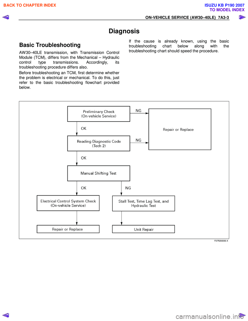
Basic Troubleshooting
AW 30–40LE transmission, with Transmission Control
Module (TCM), differs from the Mechanical – Hydraulic
control type transmissions. Accordingly, its
troubleshooting procedure differs also.
Before troubleshooting an TCM, first determine whethe
r
the problem is electrical or mechanical. To do this, just
refer to the basic troubleshooting flowchart provided
below.
If the cause is already known, using the basic
troubleshooting chart below along with the
troubleshooting chart should speed the procedure.
F07R200005-X
BACK TO CHAPTER INDEX
TO MODEL INDEX
ISUZU KB P190 2007
Page 4094 of 6020

ON-VEHICLE SERVICE (AW30–40LE) 7A3-9
Manual Shifting Test
NOTE: W ith this test, it can be determined whether the
trouble lies within the electrical circuit or is a mechanical
problem in the transmission.
1. Disconnect TCM connector
2. Inspect manual driving operation
Check that the relation of the position between
select lever and gear corresponds to the following
table.
If any abnormality is found in the above test, do
perform the stall, time lag or gear shift tests.
RTW 77ASH002901
3. Connect TCM connector
W ith the engine off, connect the TCM connector.
Stall Test
RTW 67ALH000101
The object of this test is to check the overall
performance of the transmission and engine b
y
measuring the maximum engine speeds at the “D" and
“R" positions.
NOTE:
1. Perform the test at normal operating fluid
temperature (50 – 80 °C or 122 – 176 °F).
2. Do not continuously run this test longer than 5 seconds.
BACK TO CHAPTER INDEX
TO MODEL INDEX
ISUZU KB P190 2007
Page 4242 of 6020
CONSTRUCTION AND FUNCTION 7A1-3
DESCRIPTION
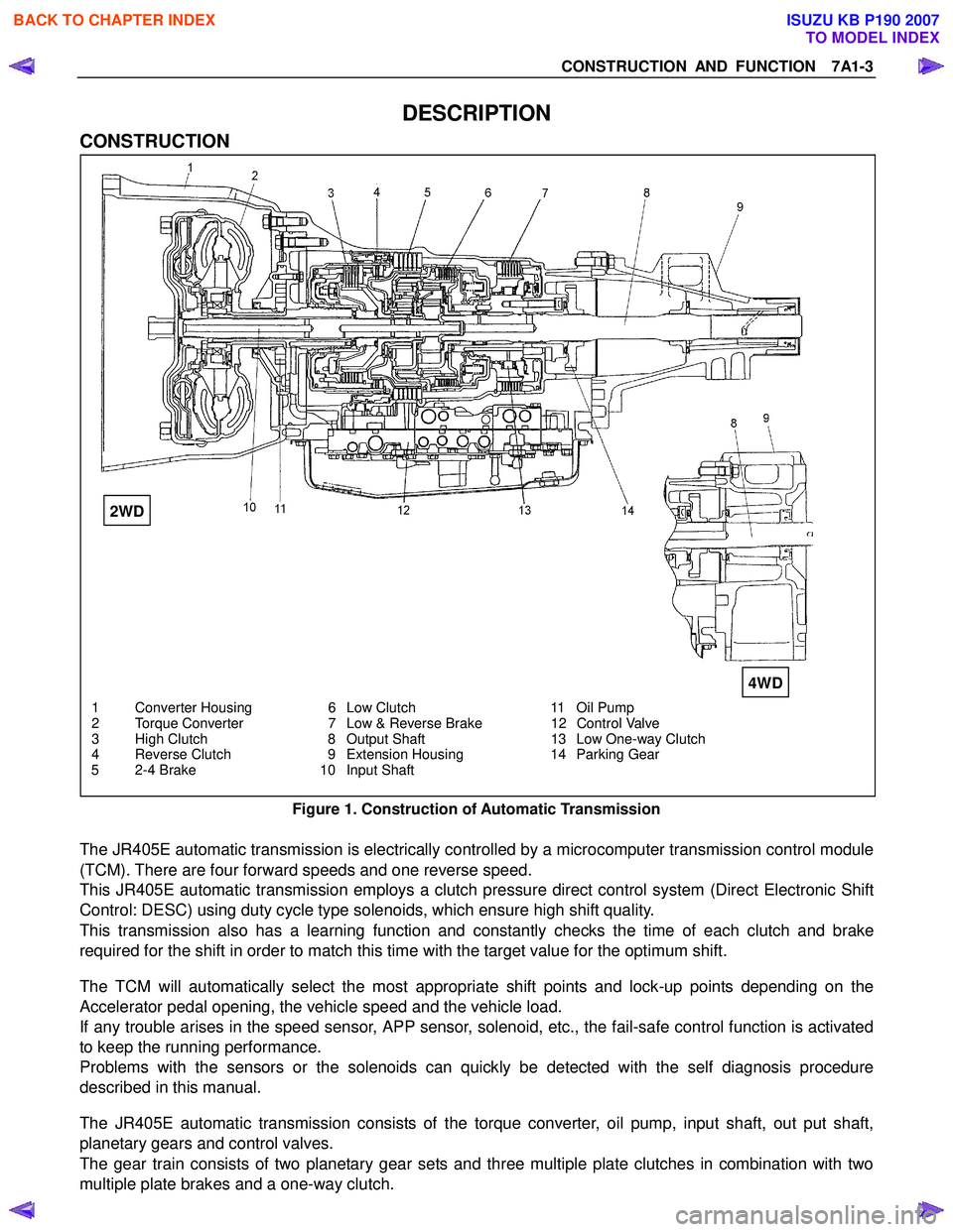
CONSTRUCTION
1 Converter Housing 6 Low Clutch 11 Oil Pump
2 Torque Converter 7 Low & Reverse Brake 12 Control Valve
3 High Clutch 8 Output Shaft 13 Low One-way Clutch
4 Reverse Clutch 9 Extension Housing 14 Parking Gear
5 2-4 Brake 10 Input Shaft
Figure 1. Construction of Automatic Transmission
The JR405E automatic transmission is electrically controlled by a microcomputer transmission control module
(TCM). There are four forward speeds and one reverse speed.
This JR405E automatic transmission employs a clutch pressure direct control system (Direct Electronic Shift
Control: DESC) using duty cycle type solenoids, which ensure high shift quality.
This transmission also has a learning function and constantly checks the time of each clutch and brake
required for the shift in order to match this time with the target value for the optimum shift.
The TCM will automatically select the most appropriate shift points and lock-up points depending on the
Accelerator pedal opening, the vehicle speed and the vehicle load.
If any trouble arises in the speed sensor, APP sensor, solenoid, etc., the fail-safe control function is activated
to keep the running performance.
Problems with the sensors or the solenoids can quickly be detected with the self diagnosis procedure
described in this manual.
The JR405E automatic transmission consists of the torque converter, oil pump, input shaft, out put shaft,
planetary gears and control valves.
The gear train consists of two planetary gear sets and three multiple plate clutches in combination with two
multiple plate brakes and a one-way clutch.
2WD
4WD
BACK TO CHAPTER INDEX
TO MODEL INDEX
ISUZU KB P190 2007
Page 4245 of 6020
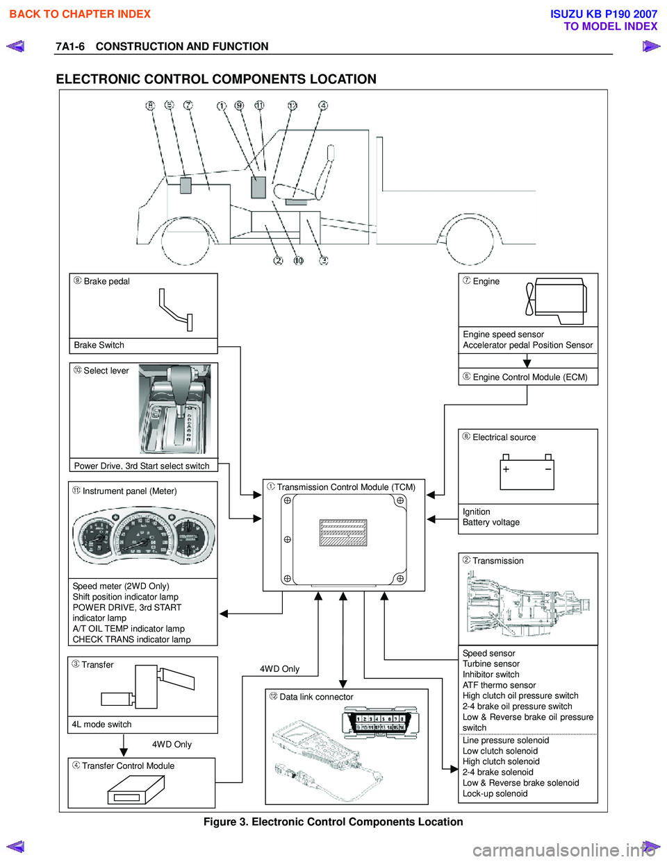
7A1-6 CONSTRUCTION AND FUNCTION
ELECTRONIC CONTROL COMPONENTS LOCATION
4WD Only 4W D Only
Instrument panel (Meter)
Speed meter (2WD Only)
Shift position indicator lamp
POWER DRIVE, 3rd START
indicator lamp
A/T OIL TEMP indicator lamp
CHECK TRANS indicator lam
p
Brake pedal
Brake Switch
Transmission Control Module (TCM)
Electrical source
Ignition
Battery voltage
Speed sensor
Turbine sensor
Inhibitor switch
ATF thermo sensor
High clutch oil pressure switch
2-4 brake oil pressure switch
Low & Reverse brake oil pressure
switch
Line pressure solenoid
Low clutch solenoid
High clutch solenoid
2-4 brake solenoid
Low & Reverse brake solenoid
Lock-up solenoid
Transmission
Transfer Control Module
Transfer
4L mode switch
Engine
Engine speed sensor
Accelerator pedal Position Sensor
Engine Control Module (ECM)
Data link connector
Select lever
Power Drive
, 3rd Start select switch
Figure 3. Electronic Control Components Location
BACK TO CHAPTER INDEX
TO MODEL INDEX
ISUZU KB P190 2007
Page 4264 of 6020
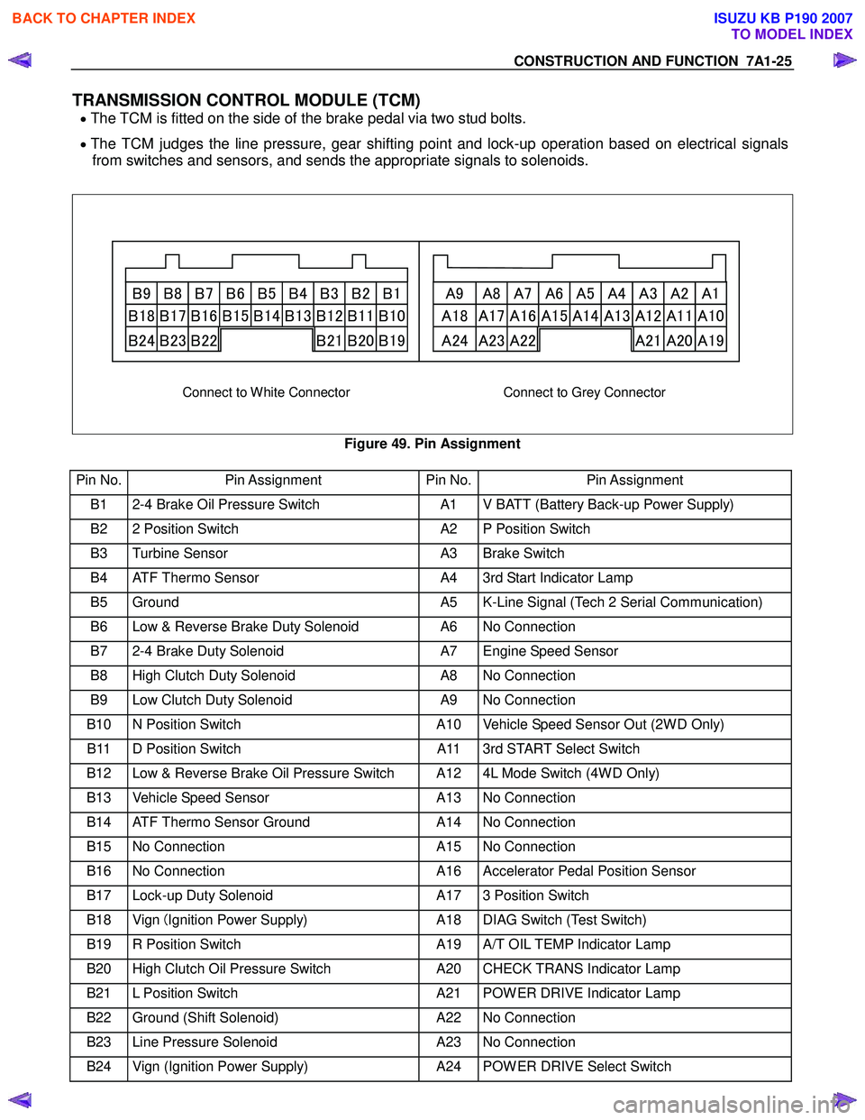
CONSTRUCTION AND FUNCTION 7A1-25
TRANSMISSION CONTROL MODULE (TCM)
• The TCM is fitted on the side of the brake pedal via two stud bolts.
• The TCM judges the line pressure, gear shifting point and lock-up operation based on electrical signals
from switches and sensors, and sends the appropriate signals to solenoids.
B9 B8 B7 B6 B5 B4 B3 B2 B1 A9 A8 A7 A6 A5 A4 A3 A2 A1
B18 B17 B16 B15 B14 B13 B12 B11 B10 A18 A17 A16 A15 A14 A13 A12 A11 A10
B24 B23 B22 B21 B20 B19 A24 A23 A22 A21 A20 A19
Connect to White Connector Connect to Grey Connector
Figure 49. Pin Assignment
Pin No. Pin Assignment Pin No.Pin Assignment
B1 2-4 Brake Oil Pressure Switch A1 V BATT (Battery Back-up Power Supply)
B2 2 Position Switch A2 P Position Switch
B3 Turbine Sensor A3 Brake Switch
B4 ATF Thermo Sensor A4 3rd Start Indicator Lamp
B5 Ground A5 K-Line Signal (Tech 2 Serial Communication)
B6 Low & Reverse Brake Duty Solenoid A6 No Connection
B7 2-4 Brake Duty Solenoid A7 Engine Speed Sensor
B8 High Clutch Duty Solenoid A8 No Connection
B9 Low Clutch Duty Solenoid A9 No Connection
B10 N Position Switch A10 Vehicle Speed Sensor Out (2W D Only)
B11 D Position Switch A11 3rd START Select Switch
B12 Low & Reverse Brake Oil Pressure Switch A12 4L Mode Switch (4W D Only)
B13 Vehicle Speed Sensor A13 No Connection
B14 ATF Thermo Sensor Ground A14 No Connection
B15 No Connection A15 No Connection
B16 No Connection A16 Accelerator Pedal Position Sensor
B17 Lock-up Duty Solenoid A17 3 Position Switch
B18 Vign (Ignition Power Supply) A18 DIAG Switch (Test Switch)
B19 R Position Switch A19 A/T OIL TEMP Indicator Lamp
B20 High Clutch Oil Pressure Switch A20 CHECK TRANS Indicator Lamp
B21 L Position Switch A21 POW ER DRIVE Indicator Lamp
B22 Ground (Shift Solenoid) A22 No Connection
B23 Line Pressure Solenoid A23 No Connection
B24 Vign (Ignition Power Supply) A24 POW ER DRIVE Select Switch
BACK TO CHAPTER INDEX
TO MODEL INDEX
ISUZU KB P190 2007
Page 4273 of 6020
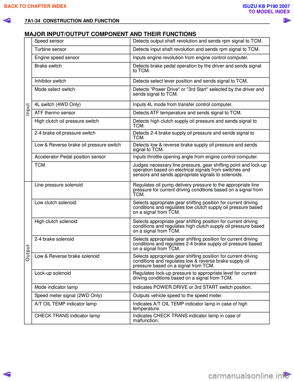
7A1-34 CONSTRUCTION AND FUNCTION
MAJOR INPUT/OUTPUT COMPONENT AND THEIR FUNCTIONS
Speed sensor Detects output shaft revolution and sends rpm signal to TCM.
Turbine sensor Detects input shaft revolution and sends rpm signal to TCM.
Engine speed sensor Inputs engine revolution from engine control computer.
Brake switch Detects brake pedal operation by the driver and sends signal
to TCM.
Inhibitor switch Detects select lever position and sends signal to TCM.
Mode select switch Detects "Power Drive" or "3rd Start" selected by the driver and
sends signal to TCM.
4L switch (4W D Only) Inputs 4L mode from transfer control computer.
ATF thermo sensor Detects ATF temperature and sends signal to TCM.
High clutch oil pressure switch Detects high clutch supply oil pressure and sends signal to
TCM.
2-4 brake oil pressure switch Detects 2-4 brake supply oil pressure and sends signal to
TCM.
Low & Reverse brake oil pressure switch Detects low & reverse brake supply oil pressure and sends signal to TCM.
Accelerator Pedal position sensor Inputs throttle opening angle from engine control computer.
Input
TCM Judges necessary line pressure, gear shifting point and lock-up
operation based on electrical signals from switches and
sensors and sends appropriate signals to solenoids.
Line pressure solenoid Regulates oil pump delivery pressure to the appropriate line
pressure for current driving conditions based on a signal from
TCM.
Low clutch solenoid Selects appropriate gear shifting position for current driving
conditions and regulates low clutch supply oil pressure based
on a signal from TCM.
High clutch solenoid Selects appropriate gear shifting position for current driving
conditions and regulates high clutch supply oil pressure based
on a signal from TCM.
2-4 brake solenoid Selects appropriate gear shifting position for current driving
conditions and regulates 2-4 brake supply oil pressure based
on a signal from TCM.
Low & Reverse brake solenoid Selects appropriate gear shifting position for current driving
conditions and regulates low & reverse brake supply oil
pressure based on a signal from TCM.
Lock-up solenoid Regulates lock-up pressure to appropriate level for current
driving conditions based on a signal from TCM.
Mode indicator lamp Indicates POW ER DRIVE or 3rd START switch position.
Speed meter signal (2W D Only) Outputs vehicle speed to the speed meter.
A/T OIL TEMP indicator lamp Indicates A/T OIL TEMP indicator lamp in case of high
temperature.
Output
CHECK TRANS indicator lamp Indicates CHECK TRANS indicator lamp in case of
malfunction.
BACK TO CHAPTER INDEX
TO MODEL INDEX
ISUZU KB P190 2007