Page 4948 of 6020
8A-10 ELECTRICAL-BODY AND CHASSIS
Solder
Apply 60/40 rosin core solder to the opening in the back of the
clip.
Follow the manufacturer’s instructions for the solder equipment
you are using.
Tape the Splice
Center and roll the splicing tape.
The tape should cover the entire splice.
Roll on enough tape to duplicate the thickness of the insulation
on the existing wires.
Do not flag the tape.
Flagged tape may not provide enough insulation, and the
flagged ends will tangle with the other wires in the harness.
If the wire does not belong in a conduit or other harness
covering, tape the wire again.
Use a winding motion to cover the first piece of tape.
BACK TO CHAPTER INDEX TO MODEL INDEXISUZU KB P190 2007
Page 4949 of 6020
ELECTRICAL-BODY AND CHASSIS 8A-11
SYMBOLS AND ABBREVIATIONS
SYMBOLS
BACK TO CHAPTER INDEXTO MODEL INDEXISUZU KB P190 2007
Page 4950 of 6020

8A-12 ELECTRICAL-BODY AND CHASSIS
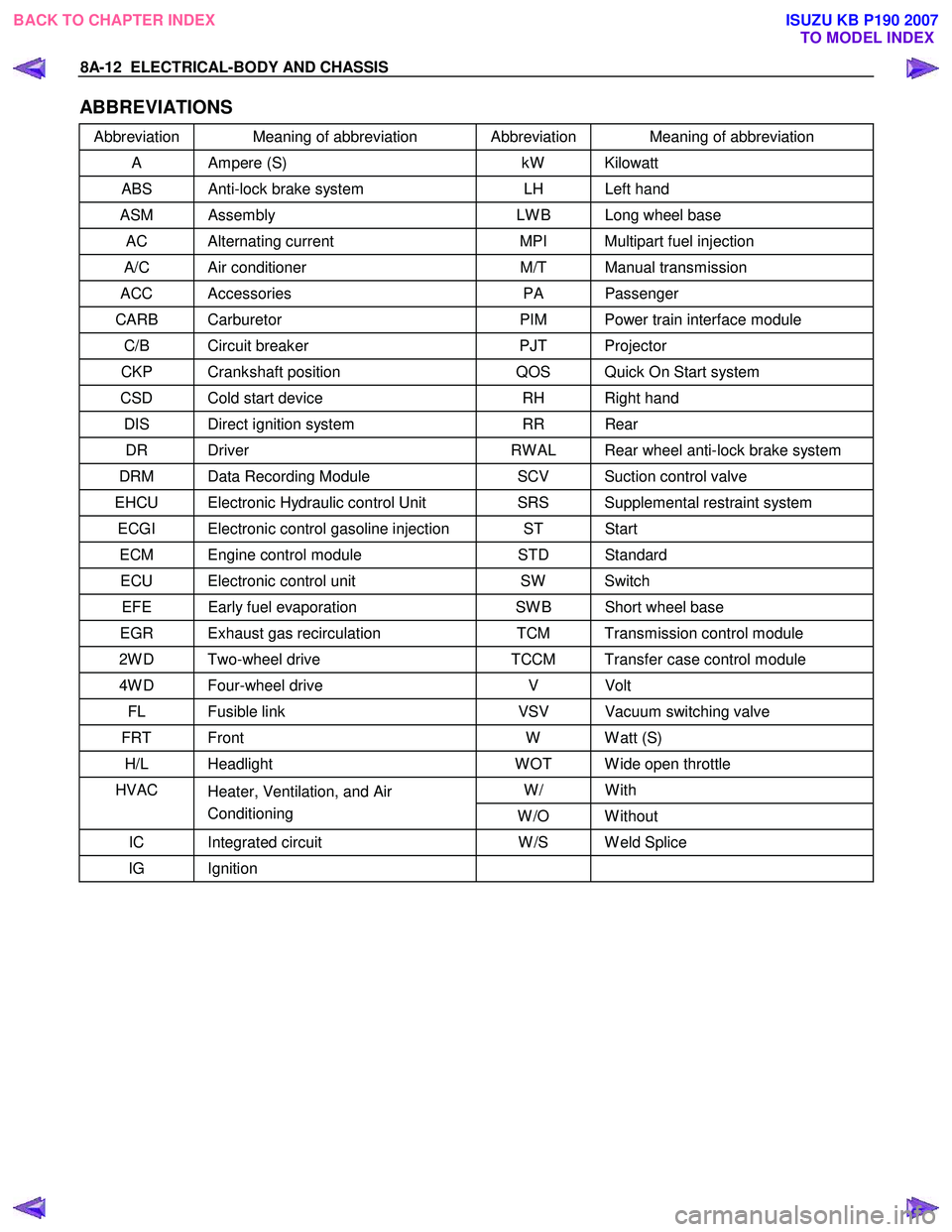
ABBREVIATIONS
Abbreviation Meaning of abbreviation Abbreviation Meaning of abbreviation
A Ampere (S) kW Kilowatt
ABS Anti-lock brake system LH Left hand
ASM Assembly LW B Long wheel base
AC Alternating current MPI Multipart fuel injection
A/C Air conditioner M/T Manual transmission
ACC Accessories PA Passenger
CARB Carburetor PIM Power train interface module
C/B Circuit breaker PJT Projector
CKP Crankshaft position QOS Quick On Start system
CSD Cold start device RH Right hand
DIS Direct ignition system RR Rear
DR Driver RW AL Rear wheel anti-lock brake system
DRM Data Recording Module SCV Suction control valve
EHCU Electronic Hydraulic control Unit SRS Supplemental restraint system
ECGI Electronic control gasoline injection ST Start
ECM Engine control module STD Standard
ECU Electronic control unit SW Switch
EFE Early fuel evaporation SW B Short wheel base
EGR Exhaust gas recirculation TCM Transmission control module
2W D Two-wheel drive TCCM Transfer case control module
4W D Four-wheel drive V Volt
FL Fusible link VSV Vacuum switching valve
FRT Front W W att (S)
H/L Headlight W OT W ide open throttle
W/ With HVAC
Heater, Ventilation, and Air
Conditioning W /O W ithout
IC Integrated circuit W /S W eld Splice
IG Ignition
BACK TO CHAPTER INDEX
TO MODEL INDEXISUZU KB P190 2007
Page 4951 of 6020
ELECTRICAL-BODY AND CHASSIS 8A-13
PARTS FOR ELECTRICAL CIRCUIT
WIRING
Wire Color
All wires have color-coded insulation.
W ires belonging to system's main harness will have a single
color.
W ires belonging to a system's sub-circuits will have a colored
stripe.
Striped wires use the following code to show wire size and
colors.
Example: 0.5 G
/ R
Red (Stripe color)
Green (Base color)
W ire size (0.5mm
2)
Abbreviations are used to indicate wire color within a circuit
diagram.
Refer to the following table.
Wire Color-Coding
Color-Coding Meaning Color-Coding Meaning
B Black BR Brown
W W hite LG Light green
R Red GR Gray
G Green P Pink
Y Yellow SB Sky blue
L Blue V Violet
O Orange
BACK TO CHAPTER INDEX
TO MODEL INDEXISUZU KB P190 2007
Page 4952 of 6020
8A-14 ELECTRICAL-BODY AND CHASSIS
Distinction of Circuit by Wire Base Color
Base color Circuits Base color Circuits
B Starter circuit and grounding circuit Y Instrument circuit
W Charging circuit L, O, BR,
R Lighting circuit LG, GR, Other circuits
G Signal circuit P, LB, V
Wire Size
W ire size is specified with the metric gauge system.
The metric gauge system gives the wire size in cross sectional
area measured in square millimeters.
Wire Size Specifications
Nominal size Cross sectional area
(mm2) Outside diameter
(mm) Allowable current
(A)
0.3 0.372 1.8 9
0.5 0.563 2.0 12
0.85 0.885 2.2 16
1.25 1.287 2.5 21
2 2.091 2.9 28
3 3.296 3.6 37.5
5 5.227 4.4 53
8 7.952 5.5 67
15 13.36 7.0 75
20 20.61 8.2 97
BACK TO CHAPTER INDEX TO MODEL INDEXISUZU KB P190 2007
Page 4953 of 6020

ELECTRICAL-BODY AND CHASSIS 8A-15
NormalBlown
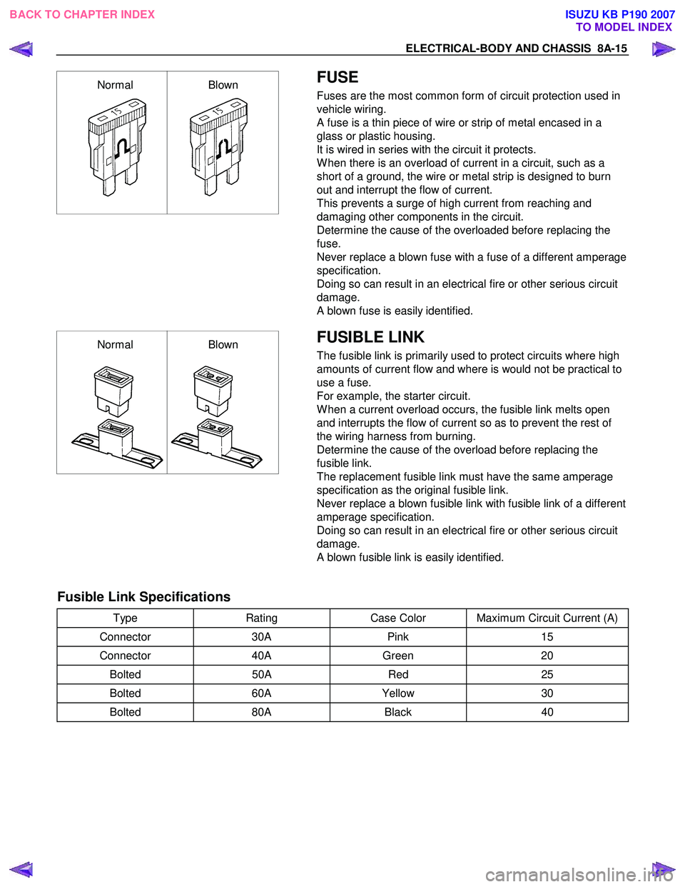
FUSE
Fuses are the most common form of circuit protection used in
vehicle wiring.
A fuse is a thin piece of wire or strip of metal encased in a
glass or plastic housing.
It is wired in series with the circuit it protects.
W hen there is an overload of current in a circuit, such as a
short of a ground, the wire or metal strip is designed to burn
out and interrupt the flow of current.
This prevents a surge of high current from reaching and
damaging other components in the circuit.
Determine the cause of the overloaded before replacing the
fuse.
Never replace a blown fuse with a fuse of a different amperage
specification.
Doing so can result in an electrical fire or other serious circuit
damage.
A blown fuse is easily identified.
Normal Blown
FUSIBLE LINK
The fusible link is primarily used to protect circuits where high
amounts of current flow and where is would not be practical to
use a fuse.
For example, the starter circuit.
W hen a current overload occurs, the fusible link melts open
and interrupts the flow of current so as to prevent the rest of
the wiring harness from burning.
Determine the cause of the overload before replacing the
fusible link.
The replacement fusible link must have the same amperage
specification as the original fusible link.
Never replace a blown fusible link with fusible link of a different
amperage specification.
Doing so can result in an electrical fire or other serious circuit
damage.
A blown fusible link is easily identified.
Fusible Link Specifications
Type Rating Case Color Maximum Circuit Current (A)
Connector 30A Pink 15
Connector 40A Green 20
Bolted 50A Red 25
Bolted 60A Yellow 30
Bolted 80A Black 40
BACK TO CHAPTER INDEX
TO MODEL INDEXISUZU KB P190 2007
Page 4954 of 6020

8A-16 ELECTRICAL-BODY AND CHASSIS
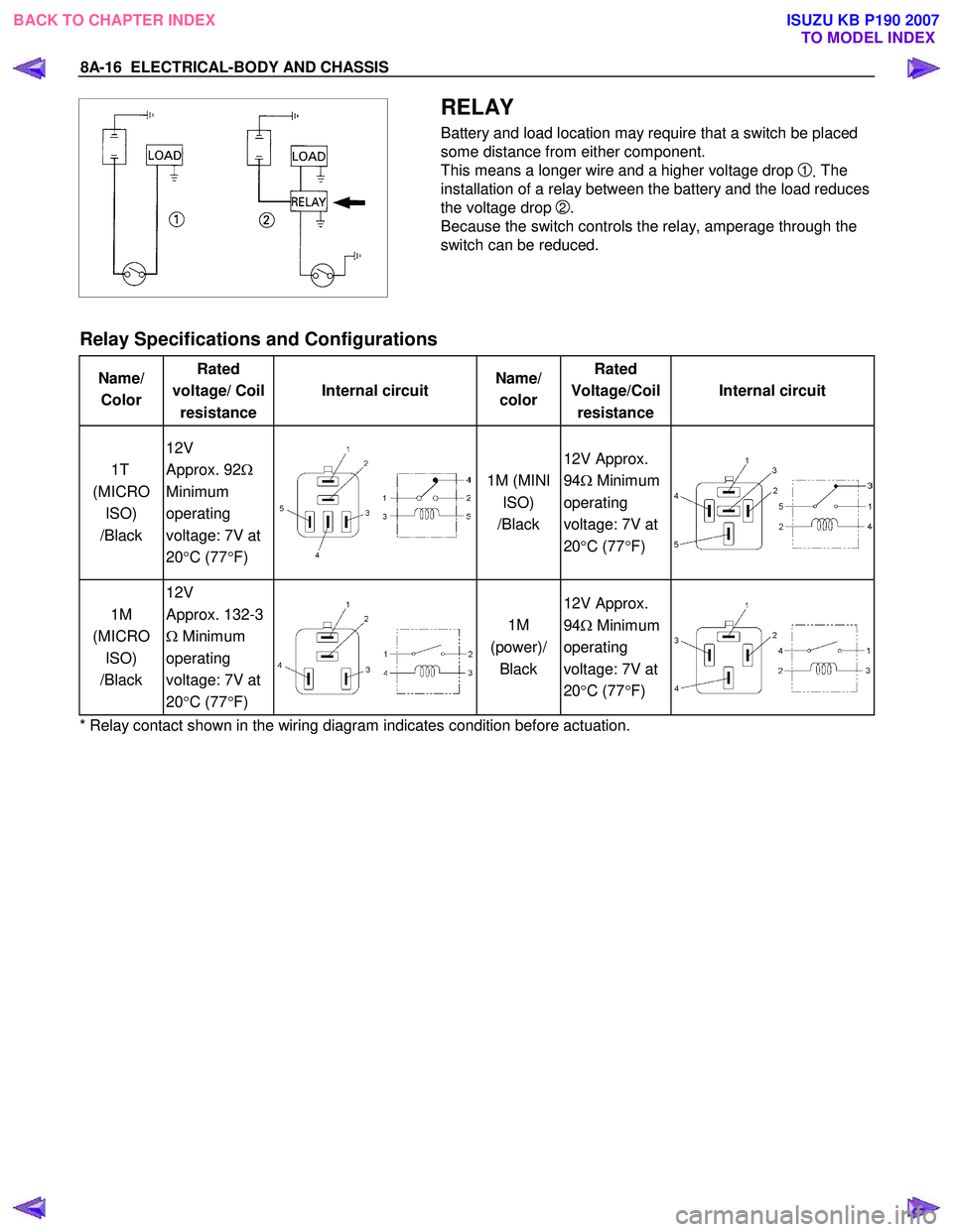
RELAY
Battery and load location may require that a switch be placed
some distance from either component.
This means a longer wire and a higher voltage drop
1. The
installation of a relay between the battery and the load reduces
the voltage drop
2.
Because the switch controls the relay, amperage through the
switch can be reduced.
Relay Specifications and Configurations
Name/ Color Rated
voltage/ Coil resistance Internal circuit
Name/
color Rated
Voltage/Coil resistance Internal circuit
1T
(MICRO ISO)
/Black 12V
Approx. 92 Ω
Minimum
operating
voltage: 7V at
20 °C (77 °F)
1M (MINI
ISO)
/Black 12V Approx.
94 Ω Minimum
operating
voltage: 7V at
20 °C (77 °F)
1M
(MICRO ISO)
/Black 12V
Approx. 132-3
Ω Minimum
operating
voltage: 7V at
20 °C (77 °F)
1M
(power)/ Black 12V Approx.
94 Ω Minimum
operating
voltage: 7V at
20 °C (77 °F)
* Relay contact shown in the wiring diagram indicates condition before actuation.
BACK TO CHAPTER INDEX TO MODEL INDEXISUZU KB P190 2007
Page 4955 of 6020
ELECTRICAL-BODY AND CHASSIS 8A-17
DIODE
Diode Specifications and Configurations
SHAPE
MARK/
COLOR
CONSTRUCTION CHECKING
THERE SHOULD BE CONTINUITY IN
EITHER A OR B W HEN A CIRCUIT
TESTER IS CONNECTED W ITH
DIODE TERMINAL
BLACK
21
CONNECTION A+-
PATTERN B-+
TERMINAL NO.
BLACK
321
-+
CONNECTION+-
PATTERN+-
-+B
A
TERMINAL NO.
BLACK
321
-+
CONNECTION+-
PATTERN+-
-+B
A
TERMINAL NO.
BLACK
4321
+-
A-+
CONNECTION-+
PATTERN-+
B+-
+-
TERMINAL NO.
Maximum Rating (Temp.=25 °
°°
°
C)
Items Rating Remarks
Peak reverse voltage 400V
Transient peak reverse voltage 500V
Average output current 1.5A Temp.=40°C
W orking ambient temperature -30°C ∼80 °C
Storage temperature -40°C ∼100ßC
BACK TO CHAPTER INDEX
TO MODEL INDEXISUZU KB P190 2007