Page 4956 of 6020
8A-18 ELECTRICAL-BODY AND CHASSIS
CONNECTOR
The connector pin shape determines whether the connector is
male or female.
The connector housing configuration does not determine
whether a connector is male or female.
The symbol illustrated in the figure is used as connector in the
circuit this section.
RTW 78ASH003101
Connector is identified with a number.
RTW 78ASH003201
The applicable terminal number is shown for each connector.
Connector terminal numbers are clearly shown.
Male side connector terminal numbers are in sequence from
upper right to lower left.
Female side connector terminal numbers are in sequence from
upper left to lower right.
NOTE:
For those connectors on which specific terminal numbers
on symbols are shown, the terminal numbers or symbols
are used in the circuit diagram, irrespective of the above
rule.
BACK TO CHAPTER INDEX TO MODEL INDEXISUZU KB P190 2007
Page 4957 of 6020
ELECTRICAL-BODY AND CHASSIS 8A-19
Battery-1
BATTERY
Inspection
1. Check the battery terminals 1 for corrosion.
2. Check the battery cables
2 for looseness.
3. Check the battery case
3 for cracks and other damage.
4. Check the battery electrolyte level.
Battery-2
Battery Replacement
1. Disconnect the battery ground cable 1.
2. Disconnect the battery positive cable
2.
3. Remove the battery clamp
3.
4. Remove the battery
Caution:
It is important that the battery ground cable be removed
first.
Removing the battery positive cable first can result in a
short circuit.
Jump Starting the Engine with a Booster Battery
The following description assumes that you are using a booster
battery mounted on a second vehicle.
The listed steps (with some minor modifications) are also
applicable if you are using a naked booster battery or special
battery charging equipment.
BACK TO CHAPTER INDEX TO MODEL INDEXISUZU KB P190 2007
Page 4958 of 6020

8A-20 ELECTRICAL-BODY AND CHASSIS
Caution:
Never push or tow the vehicle in an attempt to start it.
Extensive damage to the emission system and other
vehicle parts will result.
(Only catalytic converter vehicle)
Treat both the discharged battery and the booster battery
with great care when using jumper cables.
Carefully follow the procedure outlined below.
Always be aware of the dangers of sparking.
Failure to follow the following procedure can result in:
a. Serious personal injury, specially to your eyes.
b. Extensive property damage from a battery explosion, battery acid discharge, or electrical file.
c. Extensive damage to the electronic components o
f
both vehicles.
Do not use a 24 volt booster battery.
Serious damage to the vehicle's electrical system and
electronic components will result.
Jump Starting Procedure
1. Set the parking brake on both vehicles.
2. If one or both vehicles is equipped with a manual transmission, place the gear shift in the "NEUTRAL"
position.
3. Turn off the ignition on both vehicles.
4. Turn off all vehicle lights and accessories.
5 Be sure that the two vehicles are not touching.
Attach the end of one jumper cable to the booster battery
positive terminal.
6
Attach the other end of the same cable to the discharged
battery positive terminal.
7. Once again, check that the booster battery has a 12 volt rating.
8.
Attach one end of the remaining booster cable to the
booster battery negative terminal.
9.
Attach the other end of the booster cable to a solid ground
(such as the air conditioner compressor mounting bracket
or the alternator mounting bracket) in the engine room o
f
the vehicle with the discharged battery.
10.Be sure that the ground connection is at least 500 mm (20 in) from the discharged battery.
BACK TO CHAPTER INDEX TO MODEL INDEXISUZU KB P190 2007
Page 4959 of 6020
ELECTRICAL-BODY AND CHASSIS 8A-21
Caution:
Do not attach the booster cable to the discharged battery
negative terminal.
11. Start the engine of the vehicle with the booster battery.
Check that all unnecessary electrical accessories are off.
12. Start the engine of the vehicle with the discharged battery.
13. Remove the jumper cables in the reverse order to which they were attached.
Caution:
Be absolutely sure to remove the negative jumper cable
from the vehicle with the discharged battery first.
BACK TO CHAPTER INDEX TO MODEL INDEXISUZU KB P190 2007
Page 4960 of 6020
8A-22 ELECTRICAL-BODY AND CHASSIS
READING THE CIRCUIT DIAGRAM
In this manual, each system has its own parts location illustration and circuit diagram.
And connector configurations used in the circuit diagram are shown at the end of this manual.
PARTS LOCATION: The parts location shows the location of the connectors
1 and the harnesses 2 used in the
each system.
CIRCUIT DIAGRAM: The circuit diagram shows the power supply
3, the load or loads 4 and the grounding
point(s)
5.
CONNECTOR LIST: The connector configuration shows each connector's number
6, configuration 7 and the pin
numbers
8, parts name 9 , connector color 10.
PARTS LOCATION
RTW 780MF002401
BACK TO CHAPTER INDEX
TO MODEL INDEXISUZU KB P190 2007
Page 4961 of 6020
ELECTRICAL-BODY AND CHASSIS 8A-23
CIRCUIT DIAGRAM
CONNECTOR LIST
BACK TO CHAPTER INDEX
TO MODEL INDEXISUZU KB P190 2007
Page 4962 of 6020
8A-24 ELECTRICAL-BODY AND CHASSIS
MAIN DATA AND SPECIFICATIONS
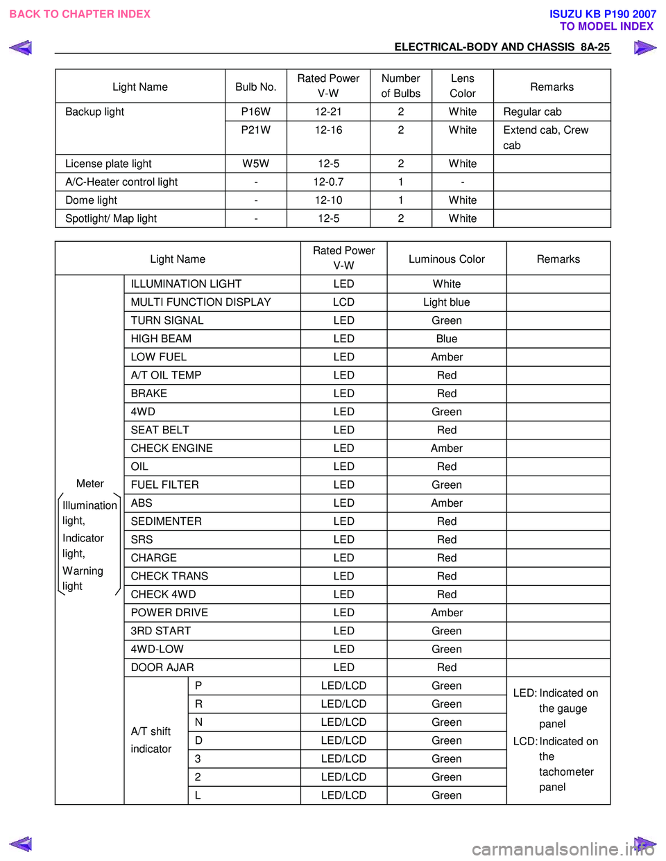
BULB SPECIFICATIONS
This illustration based on LHD
RTW 78AMF000801
Light Name Bulb No. Rated Power
V-W Number
of Bulbs Lens
Color Remarks
H4 12-60/55 2 W hite A type, Halogen
HB3 12-65 2 W hite
H7 12-55 2 W hite A type, Halogen
projector type
HB3 12-60 2 W hite High Bean
Headlight
HB4 12-51 2 W hite B type
Low Bean
High mounted stoplight W 5W 12-5 4 RED
Fog light H3 12-55 2 W hite
Front turn signal light PY21W 12-21 2 W hite Bulb Lens color
Amber
Clearance light W 5W 12-5 2 W hite
Door mirror-turn signal light
(out side mirror type) - -
2 W hite LED (Illuminated
color Amber)
Side turn signal light W 5W 12-5 2 W hite with
amber
inner lens
Rear turn signal light
PY21W 12-21 2 W hite Bulb Lens color
Amber
Rear fog light P21W 12-21 1 Red
Tail and stoplight P21/5W 12-21/5 2 Red
BACK TO CHAPTER INDEX
TO MODEL INDEXISUZU KB P190 2007
Page 4963 of 6020

ELECTRICAL-BODY AND CHASSIS 8A-25
Light Name Bulb No. Rated Power
V-W Number
of Bulbs Lens
Color Remarks
P16W 12-21 2 W hite Regular cab Backup light
P21W 12-16 2 W hite Extend cab, Crew cab
License plate light W 5W 12-5 2 W hite
A/C-Heater control light - 12-0.7 1 -
Dome light - 12-10 1 W hite
Spotlight/ Map light - 12-5 2 W hite
Light Name Rated Power
V-W Luminous Color Remarks
ILLUMINATION
LIGHT LED W hite
MULTI FUNCTION DISPLAY LCD Light blue
TURN SIGNAL LED Green
HIGH BEAM LED Blue
LOW FUEL LED Amber
A/T OIL TEMP LED Red
BRAKE LED Red
4W D LED Green
SEAT BELT LED Red
CHECK ENGINE LED Amber
OIL LED Red
FUEL FILTER LED Green
ABS LED Amber
SEDIMENTER LED Red
SRS LED Red
CHARGE LED Red
CHECK TRANS LED Red
CHECK 4W D LED Red
POW ER DRIVE LED Amber
3RD START LED Green
4W D-LOW LED Green
DOOR AJAR LED Red
P LED/LCD Green
R LED/LCD Green
N LED/LCD Green
D LED/LCD Green
3 LED/LCD Green
2 LED/LCD Green
A/T shift
indicator
L LED/LCD Green LED: Indicated on
the gauge
panel
LCD: Indicated on the
tachometer
panel
Meter
Illumination
light,
Indicator
light,
W arning
light
BACK TO CHAPTER INDEX TO MODEL INDEXISUZU KB P190 2007