Page 3741 of 6020
Powertrain Interface Module – V6 Page 6E1–80
F2: Snapshot Options
In this test mode, Tech 2 captures data before and after a snapshot triggering event that may or may not set a DTC.
Trigger Type : Manual Trigger
F0: Manual Trigger
Trigger Point : Centre
F4: Beginning
F5: Centre
F6: End
F3: Miscellaneous Tests
F0: Warnings
F1: Status Indicators
F2: Gauge Control Tests
F4: Additional Functions
W hen this selection is made from the Tech 2 screen, an additional choice is provided:
F0: Read PIM Information
F5: Program
W ithin this selection, there are two programming selections available:
F0: Program Variant Configuration
F1: Program VIN
F6: Security
F0: Immobiliser Link To ECM/PIM
F1: Reset PIM
F2: Security Information
BACK TO CHAPTER INDEX
TO MODEL INDEX
ISUZU KB P190 2007
Page 3744 of 6020

Powertrain Interface Module – V6 Page 6E1–83
13.5 Security
F0: Immobiliser Link To ECM/PIM
Should the ECM, PIM or ICU be replaced, the modules must be security linked to each other. If this linking
procedure is not performed, the vehicle will not crank nor run. For additional information relating to Tech 2
and the linking procedure, refer to 11A – Immobiliser.
NOTE
After an ECU reset, the ignition switch must be
turned Off for at least 10 seconds and then
turned On for at least one minute, before
attempting communication between Tech 2 and
the ECU.
Preconditions: TIS approval (TIS 2000 Security Access) must be obtained, the four digit security number
entered into Tech 2 and the theft deterrent system disarmed. Then the ignition must be turned ‘On’, using a
programmed remote coded key.
F1: Reset PIM
This function erases the security link between the Engine Control Module (ECM) and the Powertrain Interface Modules (PIM). If this procedure is performed, the engine will not crank nor run. A ICU Link to ECM/PIM
procedure will need to be performed. For additional information relating to the ICU Link to ECM/PIM
procedure, refer to 11A – Immobiliser.
NOTE
After an ECU reset, the ignition switch must be
turned Off for at least 10 seconds and then
turned On for at least one minute, before
attempting communication between Tech 2 and
the ECU.
Preconditions: The four digit security code must be entered into Tech 2 and the ignition switched ‘On’ with a
programmed remote coded key.
F2: Security Information
The security code is required when performing certain PIM, ICU and ECM programming functions. W hen Tech 2 requests the security code to be entered, and an incorrect code is entered, the PIM will go into a
security wait time stage. This wait time stage will prevent any further attempts to enter the security code until
the wait time has elapsed.
Should a second incorrect security code be entered after the initial wait time has elapsed, the PIM will go into a second wait time stage. The wait time will increase each time an incorrect code is entered. W hen the
correct code is entered the wait time will reset back to its original value of 10 seconds.
NOTE
The ignition switch must be in the ON position
with the battery connected during the wait time
period.
The wait time stages are as follows: • Stage 1 = 10 seconds.
• Stage 2 = 10 seconds.
• Stage 3 = 10 minutes.
• Stage 4 = 20 minutes.
• Stage 5 = 40 minutes.
• Stage 5 = 80 minutes.
BACK TO CHAPTER INDEX
TO MODEL INDEX
ISUZU KB P190 2007
Page 3908 of 6020

Automatic Transmission – 4L60E – Electrical Diagnosis Page 7C2–122
Action Taken When the DTC Sets
• The TCM requests the ECM to illuminate the MIL during the second consecutive trip in which the conditions for
setting the DTC are met.
• The TCM commands maximum line pressure.
• The TCM freezes transmission adaptive functions.
• The TCM inhibits TCC engagement.
• At the time of the first failure, the TCM records the operating conditions when the conditions for setting the DTC are
met. The TCM stores this information as a Failure Record.
• At the time of the second failure, the ECM records the operating conditions when the conditions for setting the DTC
are met. The ECM stores this information as a Freeze Frame.
• The TCM stores either DTC U0073 or DTC U0100 in TCM history during the second consecutive trip in which the
conditions for setting the DTC are met.
Conditions for Clearing the DTC
• The ECM turns off the MIL after the fourth consecutive drive trip in which the TCM does not send a MIL illumination
request.
• Tech 2 can clear the DTC.
• The TCM clears the DTC from TCM history if the vehicle completes 40 warm-up cycles without a non-emission
related diagnostic fault occurring.
• The TCM cancels the DTC default actions when the ignition is off long enough to power down the TCM.
Test Description
The following number refers to the step numbers in the diagnostic table:
1 The following tests are included in the Diagnostic System Check.
• Tests the integrity of the GM LAN serial data communication circuit.
• Tests for fault conditions on the vehicle immobiliser system stored in the ICU.
DTC P0864 and U0101 Diagnostic Table
Step Action Yes No
1 Has the Diagnostic System Check been performed?
Go to Step 2 Refer to
4.7 Diagnostic System Check
BACK TO CHAPTER INDEX
TO MODEL INDEX
ISUZU KB P190 2007
Page 3997 of 6020

TRANSMISSION CONTROL SYSTEM (AW30–40LE) 7A2-31
2.Demand of Data
1. Connect Tech 2 to the vehicle. W hen activated b
y
turning on the power of Tech 2, push the "Enter"
switch.
2. Turn on the ignition switch (without starting the
engine)
3. In the main menu of Diagnostic Tester, push "F1:
Service Programming System (SPS)".
4. Push “F0: Request Info” of Tech 2.
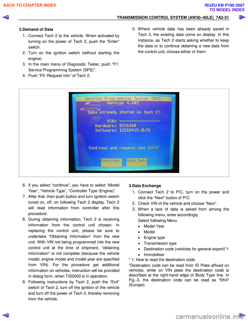
5. W here vehicle data has been already saved in
Tech 2, the existing data come on display. In this
instance, as Tech 2 starts asking whether to keep
the data or to continue obtaining a new data from
the control unit, choose either of them.
6. If you select “continue”, you have to select “Model
Year”, “Vehicle Type”, “Controller Type (Engine)”.
7.
After that. then push button and turn Ignition switch
tuned on, off, on following Tech 2 display. Tech 2
will read information from controller after this
procedure.
8. During obtaining information, Tech 2 is receiving
information from the control unit chosen. In
replacing the control unit, please be sure to
undertake “Obtaining Information” from the ne
w
unit. W ith VIN not being programmed into the new
control unit at the time of shipment, "obtaining
information" is not complete (because the vehicle
model, engine model and model year are specified
from VIN). For the procedure get additional
information on vehicles, instruction will be provided
in dialog form, when TIS2000 is in operation.
9. Following instructions by Tech 2, push the “Exit”
switch of Tech 2, turn off the ignition of the vehicle
and turn off the power of Tech 2, thereby removing
from the vehicle.
3.Data Exchange
1. Connect Tech 2 to P/C, turn on the power and
click the “Next” button of P/C.
2. Check VIN of the vehicle and choose “Next”.
3. W hen a lack of data is asked from among the
following menu, enter accordingly.
Select following Menu
• Model Year
• Model
• Engine type
• Transmission type
• Destination code (vehicles for general export)*1
• Immobiliser
* 1: How to read the destination code
"Destination code can be read from ID Plate affixed on
vehicles, while on VIN plate the destination code is
described at the right-hand edge of Body Type line. In
Fig.-3, the destination code can be read as “EK4”
(Europe).
BACK TO CHAPTER INDEX
TO MODEL INDEX
ISUZU KB P190 2007