2007 ISUZU KB P190 IMMOBILISER
[x] Cancel search: IMMOBILISERPage 3672 of 6020
Powertrain Interface Module – V6 Page 6E1–11
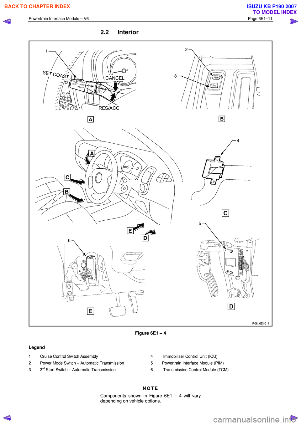
2.2 Interior
Figure 6E1 – 4
Legend
1 Cruise Control Switch Assembly
2 Power Mode Switch – Automatic Transmission
3 3
rd Start Switch – Automatic Transmission
4 Immobiliser Control Unit (ICU)
5 Powertrain Interface Module (PIM)
6 Transmission Control Module (TCM)
NOTE
Components shown in Figure 6E1 – 4 will vary
depending on vehicle options.
BACK TO CHAPTER INDEX
TO MODEL INDEX
ISUZU KB P190 2007
Page 3673 of 6020
Powertrain Interface Module – V6 Page 6E1–12
3 Component Description and
Operation
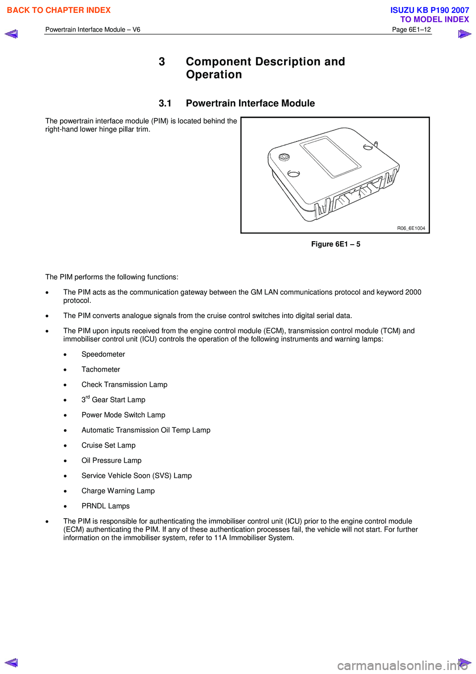
3.1 Powertrain Interface Module
The powertrain interface module (PIM) is located behind the
right-hand lower hinge pillar trim.
Figure 6E1 – 5
The PIM performs the following functions:
• The PIM acts as the communication gateway between the GM LAN communications protocol and keyword 2000
protocol.
• The PIM converts analogue signals from the cruise control switches into digital serial data.
• The PIM upon inputs received from the engine control module (ECM), transmission control module (TCM) and
immobiliser control unit (ICU) controls the operation of the following instruments and warning lamps:
• Speedometer
• Tachometer
• Check Transmission Lamp
• 3
rd Gear Start Lamp
• Power Mode Switch Lamp
• Automatic Transmission Oil Temp Lamp
• Cruise Set Lamp
• Oil Pressure Lamp
• Service Vehicle Soon (SVS) Lamp
• Charge W arning Lamp
• PRNDL Lamps
• The PIM is responsible for authenticating the immobiliser control unit (ICU) prior to the engine control module
(ECM) authenticating the PIM. If any of these authentication processes fail, the vehicle will not start. For further
information on the immobiliser system, refer to 11A Immobiliser System.
BACK TO CHAPTER INDEX
TO MODEL INDEX
ISUZU KB P190 2007
Page 3674 of 6020
Powertrain Interface Module – V6 Page 6E1–13
3.2 Powertrain Interface Module Gateway
Components
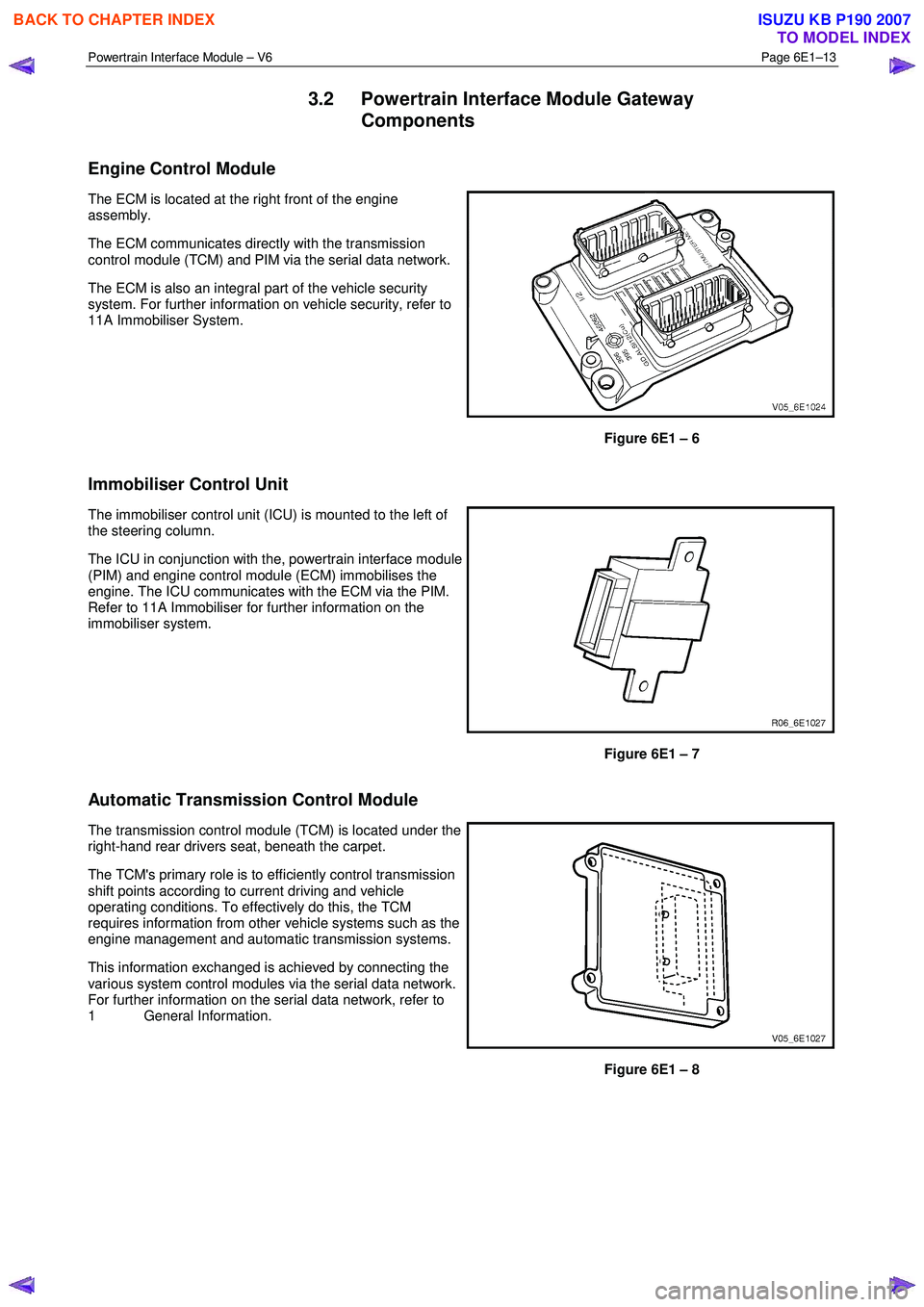
Engine Control Module
The ECM is located at the right front of the engine
assembly.
The ECM communicates directly with the transmission
control module (TCM) and PIM via the serial data network.
The ECM is also an integral part of the vehicle security
system. For further information on vehicle security, refer to
11A Immobiliser System.
Figure 6E1 – 6
Immobiliser Control Unit
The immobiliser control unit (ICU) is mounted to the left of
the steering column.
The ICU in conjunction with the, powertrain interface module
(PIM) and engine control module (ECM) immobilises the
engine. The ICU communicates with the ECM via the PIM.
Refer to 11A Immobiliser for further information on the
immobiliser system.
Figure 6E1 – 7
Automatic Transmission Control Module
The transmission control module (TCM) is located under the
right-hand rear drivers seat, beneath the carpet.
The TCM's primary role is to efficiently control transmission
shift points according to current driving and vehicle
operating conditions. To effectively do this, the TCM
requires information from other vehicle systems such as the
engine management and automatic transmission systems.
This information exchanged is achieved by connecting the
various system control modules via the serial data network.
For further information on the serial data network, refer to
1 General Information.
Figure 6E1 – 8
BACK TO CHAPTER INDEX
TO MODEL INDEX
ISUZU KB P190 2007
Page 3682 of 6020
Powertrain Interface Module – V6 Page 6E1–21
6.3 Connector Information
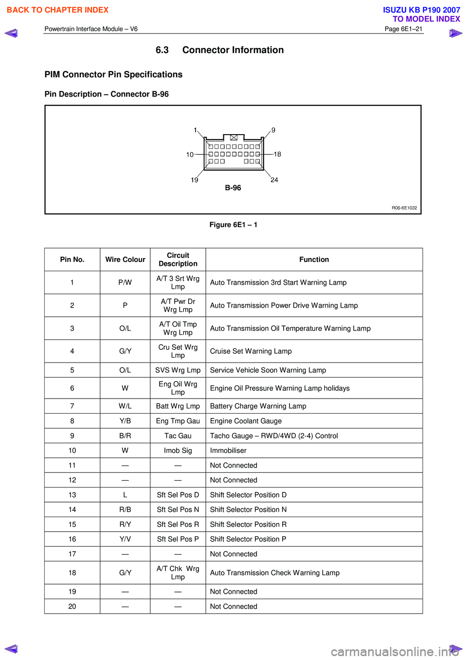
PIM Connector Pin Specifications
Pin Description – Connector B-96
Figure 6E1 – 1
Pin No. Wire Colour Circuit
Description Function
1 P/W
A/T 3 Srt W rg
Lmp Auto Transmission 3rd Start W arning Lamp
2 P
A/T Pwr Dr
W rg Lmp Auto Transmission Power Drive W arning Lamp
3 O/L A/T Oil Tmp
W rg Lmp Auto Transmission Oil Temperature W arning Lamp
4 G/Y
Cru Set W rg
Lmp Cruise Set W arning Lamp
5
O/L SVS W rg Lmp Service Vehicle Soon W arning Lamp
6 W Eng Oil W rg
Lmp Engine Oil Pressure W arning Lamp holidays
7
W /L Batt W rg Lmp Battery Charge W arning Lamp
8 Y/B Eng Tmp Gau Engine Coolant Gauge
9 B/R Tac Gau Tacho Gauge – RW D/4W D (2-4) Control
10 W Imob Sig Immobiliser
11 — — Not Connected
12 — — Not Connected
13 L Sft Sel Pos D Shift Selector Position D
14 R/B Sft Sel Pos N Shift Selector Position N
15 R/Y Sft Sel Pos R Shift Selector Position R
16 Y/V Sft Sel Pos P Shift Selector Position P
17 — — Not Connected
18 G/Y A/T Chk W rg
Lmp Auto Transmission Check W arning Lamp
19 — — Not
Connected
20 — — Not Connected
BACK TO CHAPTER INDEX
TO MODEL INDEX
ISUZU KB P190 2007
Page 3690 of 6020

Powertrain Interface Module – V6 Page 6E1–29
Intermittent Fault Conditions
8.1 Intermittent Conditions Diagnostic Table
Description
A fault condition is intermittent if one of the following conditions exists:
• The fault condition is not always present.
• The fault condition cannot be presently duplicated.
• There is no Current DTC but a History DTC is stored.
Diagnostic Table
Checks Actions
Preliminary
• Perform the Preliminary Checks, refer to 7.1 Diagnostic Requirements,
Precautions and Preliminary Checks.
• Gather information from the customer regarding the conditions that trigger the
intermittent fault such as:
• At what engine or ambient temperature range does the fault occur?
• Does the fault occur when operating aftermarket electrical equipment inside
the vehicle?
• Does the fault occur on rough roads or in wet road conditions?
• If the intermittent fault is a start and then stall condition, check immobiliser system.
Refer to 11A Immobiliser.
Harness / Connector Install Tech 2 and perform the Tech 2 Intermittent Fault Tests. Refer to 4.1 Diagnostic General Descriptions for information on Tech 2 ECU diagnostic
tests.
W arning Indicator The following conditions may cause an intermittent Malfunction Indicator Lamp fault with
no DTC listed:
• Electromagnetic Interference (EMI) caused by a faulty relay, ECM controlled
solenoid, switch or other external source.
• Incorrect installation of aftermarket electrical equipment such as the following:
• mobile phones,
• theft deterrent alarms,
• lights, or
• radio equipment.
• Loose PIM ground connections.
BACK TO CHAPTER INDEX
TO MODEL INDEX
ISUZU KB P190 2007
Page 3693 of 6020
Powertrain Interface Module – V6 Page 6E1–32
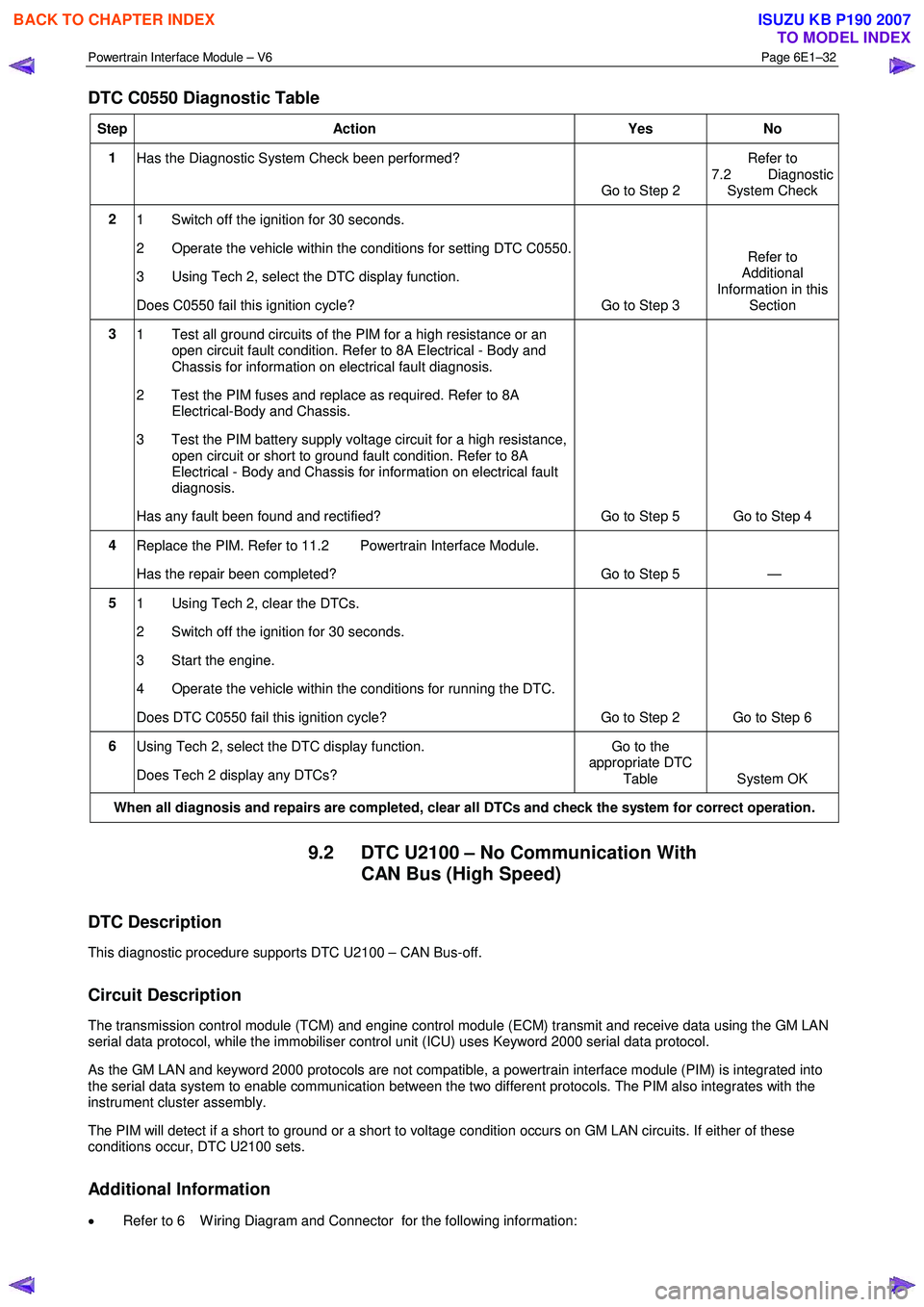
DTC C0550 Diagnostic Table
Step Action Yes No
1
Has the Diagnostic System Check been performed?
Go to Step 2 Refer to
7.2 Diagnostic System Check
2 1 Switch off the ignition for 30 seconds.
2 Operate the vehicle within the conditions for setting DTC C0550.
3 Using Tech 2, select the DTC display function.
Does C0550 fail this ignition cycle? Go to Step 3 Refer to
Additional
Information in this Section
3 1 Test all ground circuits of the PIM for a high resistance or an
open circuit fault condition. Refer to 8A Electrical - Body and
Chassis for information on electrical fault diagnosis.
2 Test the PIM fuses and replace as required. Refer to 8A Electrical-Body and Chassis.
3 Test the PIM battery supply voltage circuit for a high resistance, open circuit or short to ground fault condition. Refer to 8A
Electrical - Body and Chassis for information on electrical fault
diagnosis.
Has any fault been found and rectified? Go to Step 5 Go to Step 4
4 Replace the PIM. Refer to 11.2 Powertrain Interface Module.
Has the repair been completed? Go to Step 5 —
5 1 Using Tech 2, clear the DTCs.
2 Switch off the ignition for 30 seconds.
3 Start the engine.
4 Operate the vehicle within the conditions for running the DTC.
Does DTC C0550 fail this ignition cycle? Go to Step 2 Go to Step 6
6 Using Tech 2, select the DTC display function.
Does Tech 2 display any DTCs? Go to the
appropriate DTC
Table System OK
When all diagnosis and repairs are completed, clear all DTCs and check the system for correct operation.
9.2 DTC U2100 – No Communication With CAN Bus (High Speed)
DTC Description
This diagnostic procedure supports DTC U2100 – CAN Bus-off.
Circuit Description
The transmission control module (TCM) and engine control module (ECM) transmit and receive data using the GM LAN
serial data protocol, while the immobiliser control unit (ICU) uses Keyword 2000 serial data protocol.
As the GM LAN and keyword 2000 protocols are not compatible, a powertrain interface module (PIM) is integrated into
the serial data system to enable communication between the two different protocols. The PIM also integrates with the
instrument cluster assembly.
The PIM will detect if a short to ground or a short to voltage condition occurs on GM LAN circuits. If either of these
conditions occur, DTC U2100 sets.
Additional Information
• Refer to 6 W iring Diagram and Connector for the following information:
BACK TO CHAPTER INDEX
TO MODEL INDEX
ISUZU KB P190 2007
Page 3696 of 6020
Powertrain Interface Module – V6 Page 6E1–35
Step Action Yes No
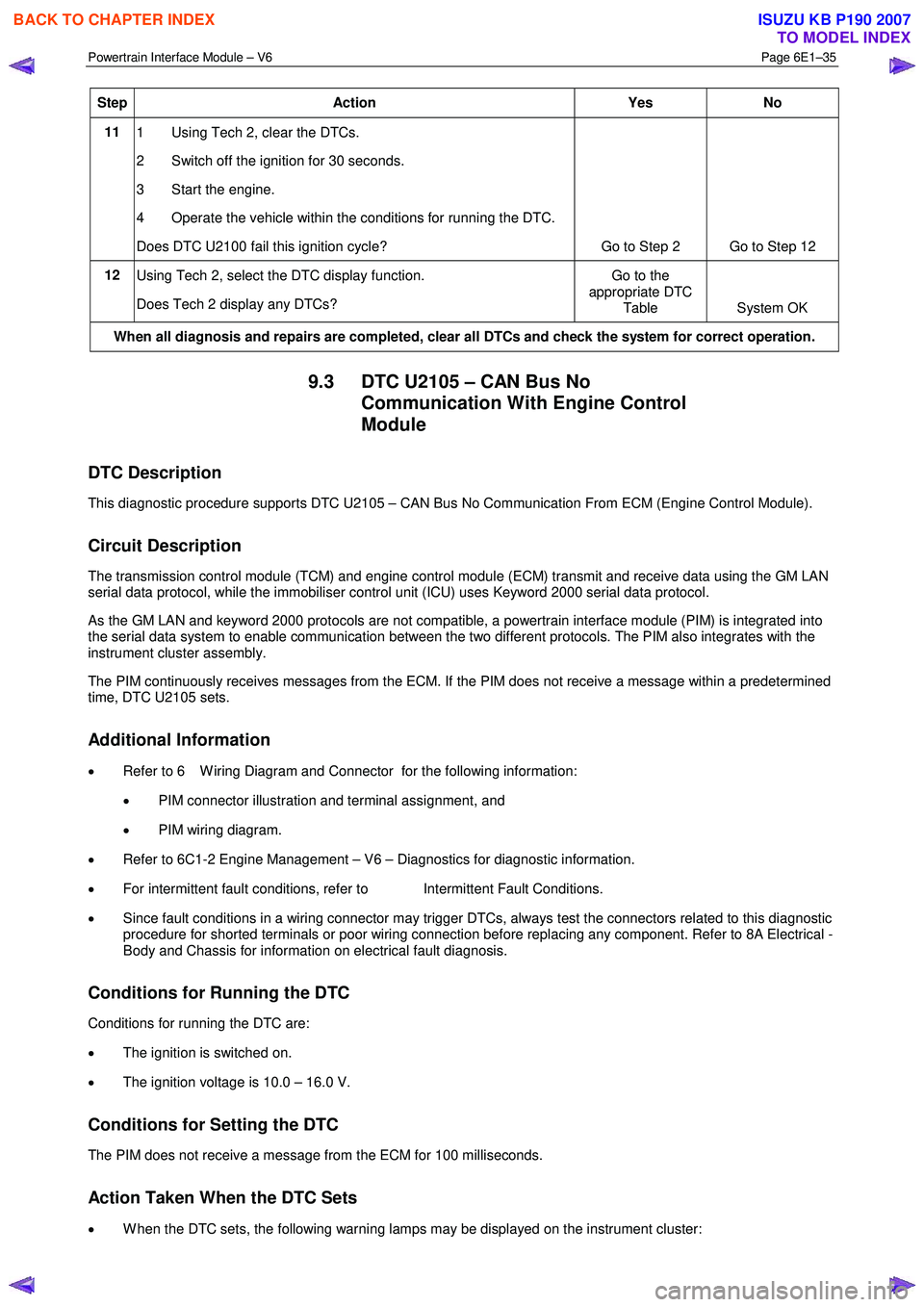
11
1 Using Tech 2, clear the DTCs.
2 Switch off the ignition for 30 seconds.
3 Start the engine.
4 Operate the vehicle within the conditions for running the DTC.
Does DTC U2100 fail this ignition cycle? Go to Step 2 Go to Step 12
12
Using Tech 2, select the DTC display function.
Does Tech 2 display any DTCs? Go to the
appropriate DTC Table System OK
When all diagnosis and repairs are completed, clear all DTCs and check the system for correct operation.
9.3 DTC U2105 – CAN Bus No
Communication With Engine Control
Module
DTC Description
This diagnostic procedure supports DTC U2105 – CAN Bus No Communication From ECM (Engine Control Module).
Circuit Description
The transmission control module (TCM) and engine control module (ECM) transmit and receive data using the GM LAN
serial data protocol, while the immobiliser control unit (ICU) uses Keyword 2000 serial data protocol.
As the GM LAN and keyword 2000 protocols are not compatible, a powertrain interface module (PIM) is integrated into
the serial data system to enable communication between the two different protocols. The PIM also integrates with the
instrument cluster assembly.
The PIM continuously receives messages from the ECM. If the PIM does not receive a message within a predetermined
time, DTC U2105 sets.
Additional Information
• Refer to 6 W iring Diagram and Connector for the following information:
• PIM connector illustration and terminal assignment, and
• PIM wiring diagram.
• Refer to 6C1-2 Engine Management – V6 – Diagnostics for diagnostic information.
• For intermittent fault conditions, refer to Intermittent Fault Conditions.
• Since fault conditions in a wiring connector may trigger DTCs, always test the connectors related to this diagnostic
procedure for shorted terminals or poor wiring connection before replacing any component. Refer to 8A Electrical -
Body and Chassis for information on electrical fault diagnosis.
Conditions for Running the DTC
Conditions for running the DTC are:
• The ignition is switched on.
• The ignition voltage is 10.0 – 16.0 V.
Conditions for Setting the DTC
The PIM does not receive a message from the ECM for 100 milliseconds.
Action Taken When the DTC Sets
• W hen the DTC sets, the following warning lamps may be displayed on the instrument cluster:
BACK TO CHAPTER INDEX
TO MODEL INDEX
ISUZU KB P190 2007
Page 3699 of 6020
Powertrain Interface Module – V6 Page 6E1–38
9.4 DTC U2106 – CAN Bus No
Communication With Transmission
Control Module
DTC Description
This diagnostic procedure supports DTC U2106 – CAN Bus No Communication W ith TCM (Transmission Control
Module).
Circuit Description
The transmission control module (TCM) and engine control module (ECM) transmit and receive data using the GM LAN
serial data protocol, while the immobiliser control unit (ICU) uses Keyword 2000 serial data protocol.
As the GM LAN and keyword 2000 protocols are not compatible, a powertrain interface module (PIM) is integrated into
the serial data system to enable communication between the two different protocols. The PIM also integrates with the
instrument cluster assembly.
The PIM continuously receives messages from the TCM. If the PIM does not receive a message within a predetermined
time, DTC U2106 sets.
Additional Information
• Refer to 6 W iring Diagram and Connector for the following information:
• PIM connector illustration and terminal assignment, and
• PIM wiring diagram.
• For intermittent fault conditions, refer to Intermittent Fault Conditions.
• Since fault conditions in a wiring connector may trigger DTCs, always test the connectors related to this diagnostic
procedure for shorted terminals or poor wiring connection before replacing any component. Refer to 8A Electrical -
Body and Chassis for information on electrical fault diagnosis.
Conditions for Running the DTC
Conditions for running the DTC are:
• The ignition is switched on.
• The ignition voltage is 10.0 – 16.0 V.
Conditions for Setting the DTC
The PIM does not receive a message from the TCM for 1000 milliseconds, during the current ignition cycle.
Action Taken When the DTC Sets
• W hen the DTC sets, the following warning lamps may be displayed on the instrument cluster:
• Malfunction Indicator Lamp,
• Service Vehicle Soon.
Conditions for Clearing the DTC
Refer to 4.1 Diagnostic General Descriptions for information on the conditions for clearing DTCs.
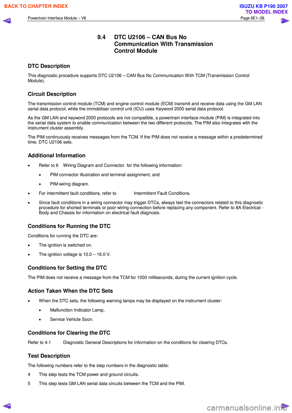
Test Description
The following numbers refer to the step numbers in the diagnostic table:
4 This step tests the TCM power and ground circuits.
5 This step tests GM LAN serial data circuits between the TCM and the PIM.
BACK TO CHAPTER INDEX
TO MODEL INDEX
ISUZU KB P190 2007