2007 ISUZU KB P190 IMMOBILISER
[x] Cancel search: IMMOBILISERPage 3544 of 6020
Engine Management – V6 – Service Operations Page 6C1-3–20
Reinstall
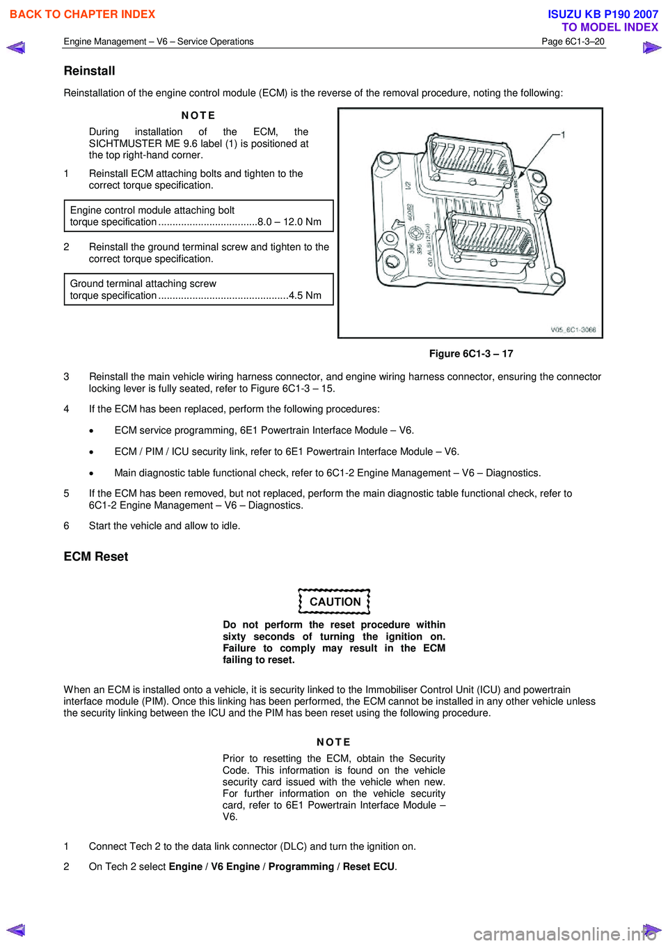
Reinstallation of the engine control module (ECM) is the reverse of the removal procedure, noting the following:
NOTE
During installation of the ECM, the
SICHTMUSTER ME 9.6 label (1) is positioned at
the top right-hand corner.
1 Reinstall ECM attaching bolts and tighten to the correct torque specification.
Engine control module attaching bolt
torque specification ...................................8.0 – 12.0 Nm
2 Reinstall the ground terminal screw and tighten to the correct torque specification.
Ground terminal attaching screw
torque specification ..............................................4.5 Nm
Figure 6C1-3 – 17
3 Reinstall the main vehicle wiring harness connector, and engine wiring harness connector, ensuring the connector locking lever is fully seated, refer to Figure 6C1-3 – 15.
4 If the ECM has been replaced, perform the following procedures:
• ECM service programming, 6E1 Powertrain Interface Module – V6.
• ECM / PIM / ICU security link, refer to 6E1 Powertrain Interface Module – V6.
• Main diagnostic table functional check, refer to 6C1-2 Engine Management – V6 – Diagnostics.
5 If the ECM has been removed, but not replaced, perform the main diagnostic table functional check, refer to 6C1-2 Engine Management – V6 – Diagnostics.
6 Start the vehicle and allow to idle.
ECM Reset
Do not perform the reset procedure within
sixty seconds of turning the ignition on.
Failure to comply may result in the ECM
failing to reset.
W hen an ECM is installed onto a vehicle, it is security linked to the Immobiliser Control Unit (ICU) and powertrain
interface module (PIM). Once this linking has been performed, the ECM cannot be installed in any other vehicle unless
the security linking between the ICU and the PIM has been reset using the following procedure.
NOTE
Prior to resetting the ECM, obtain the Security
Code. This information is found on the vehicle
security card issued with the vehicle when new.
For further information on the vehicle security
card, refer to 6E1 Powertrain Interface Module –
V6.
1 Connect Tech 2 to the data link connector (DLC) and turn the ignition on.
2 On Tech 2 select Engine / V6 Engine / Programming / Reset ECU .
BACK TO CHAPTER INDEX
TO MODEL INDEX
ISUZU KB P190 2007
Page 3618 of 6020
Starting System – V6 Page 6D1-2–10
2.5 Starting System Inoperative /
Malfunctioning
Circuit Description
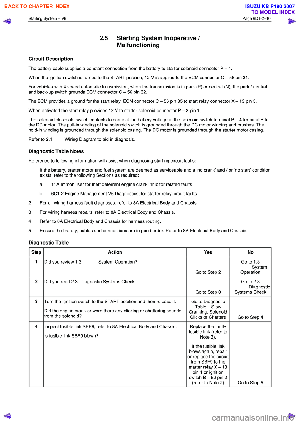
The battery cable supplies a constant connection from the battery to starter solenoid connector P – 4.
W hen the ignition switch is turned to the START position, 12 V is applied to the ECM connector C – 56 pin 31.
For vehicles with 4 speed automatic transmission, when the transmission is in park (P) or neutral (N), the park / neutral
and back-up switch grounds ECM connector C – 56 pin 32.
The ECM provides a ground for the start relay, ECM connector C – 56 pin 35 to start relay connector X – 13 pin 5.
W hen activated the start relay provides 12 V to starter solenoid connector P – 3 pin 1.
The solenoid closes its switch contacts to connect the battery voltage at the solenoid switch terminal P – 4 terminal B to
the DC motor. The pull-in winding of the solenoid switch is grounded through the DC motor winding and brushes. The
hold-in winding is grounded through the solenoid casing. The DC motor is grounded through the starter motor casing.
Refer to 2.4 W iring Diagram to aid in diagnosis.
Diagnostic Table Notes
Reference to following information will assist when diagnosing starting circuit faults:
1 If the battery, starter motor and fuel system are deemed as serviceable and a ‘no crank’ and / or ‘no start’ condition exists, refer to the following Sections as required:
a 11A Immobiliser for theft deterrent engine crank inhibitor related faults
b 6C1-2 Engine Management V6 Diagnostics, for starter relay circuit faults
2 For all wiring harness fault diagnoses, refer to 8A Electrical Body and Chassis.
3 For wiring harness repairs, refer to 8A Electrical Body and Chassis.
4 Refer to 8A Electrical Body and Chassis for harness routing.
5 Ensure the battery, cables and connections are in good order. Refer to 8A Electrical Body and Chassis.
Diagnostic Table
Step Action Yes No
1
Did you review 1.3 System Operation?
Go to Step 2 Go to 1.3
System
Operation
2 Did you read 2.3 Diagnostic Systems Check
Go to Step 3 Go to 2.3
Diagnostic Systems Check
3 Turn the ignition switch to the START position and then release it.
Did the engine crank or were there any clicking or chattering sounds
from the solenoid? Go to Diagnostic
Table – Slow
Cranking, Solenoid Clicks or Chatters Go to Step 4
4 Inspect fusible link SBF9, refer to 8A Electrical Body and Chassis.
Is fusible link SBF9 blown? Replace the faulty
fusible link (refer to
Note 3).
If the fusible link
blows again, repair
or replace the circuit from SBF9 to the
starter relay X – 13 pin 1 or ignition
switch B – 62 pin 2 (refer to Note 2) Go to Step 5
BACK TO CHAPTER INDEX
TO MODEL INDEX
ISUZU KB P190 2007
Page 3651 of 6020
Battery Page 6D1-3–11
b W ait 15 seconds for the battery to recover.
8 If possible, set the selector to 50% of rapid discharge current (or three times the 20 hour discharge rate).
9 Apply the load test for 10 seconds and record the battery voltage. If one cell is faulty it will gas excessively or overheat. This indicates a faulty battery.
10 Recharge the battery if the voltage is at or below the minimum voltage specified by the HRD manufacturer (or 9.6 V).
11 Replace the battery if the voltage is below the minimum voltage specified by the HRD manufacturer (or below 9.6 V after the battery is charged and the test is repeated). Refer to 4.1 Battery.
12 Connect the battery positive terminal.
13 Connect the battery negative terminal.
Alternate Load Test
If HRD test equipment is not available, test the battery as follows:
1 Read and obey the safety precautions for working with batteries, refer to 2 Safety Precautions.
2 Ensure the state of the battery is at least 65% charged. Refer to 3.3 Hydrometer Test.
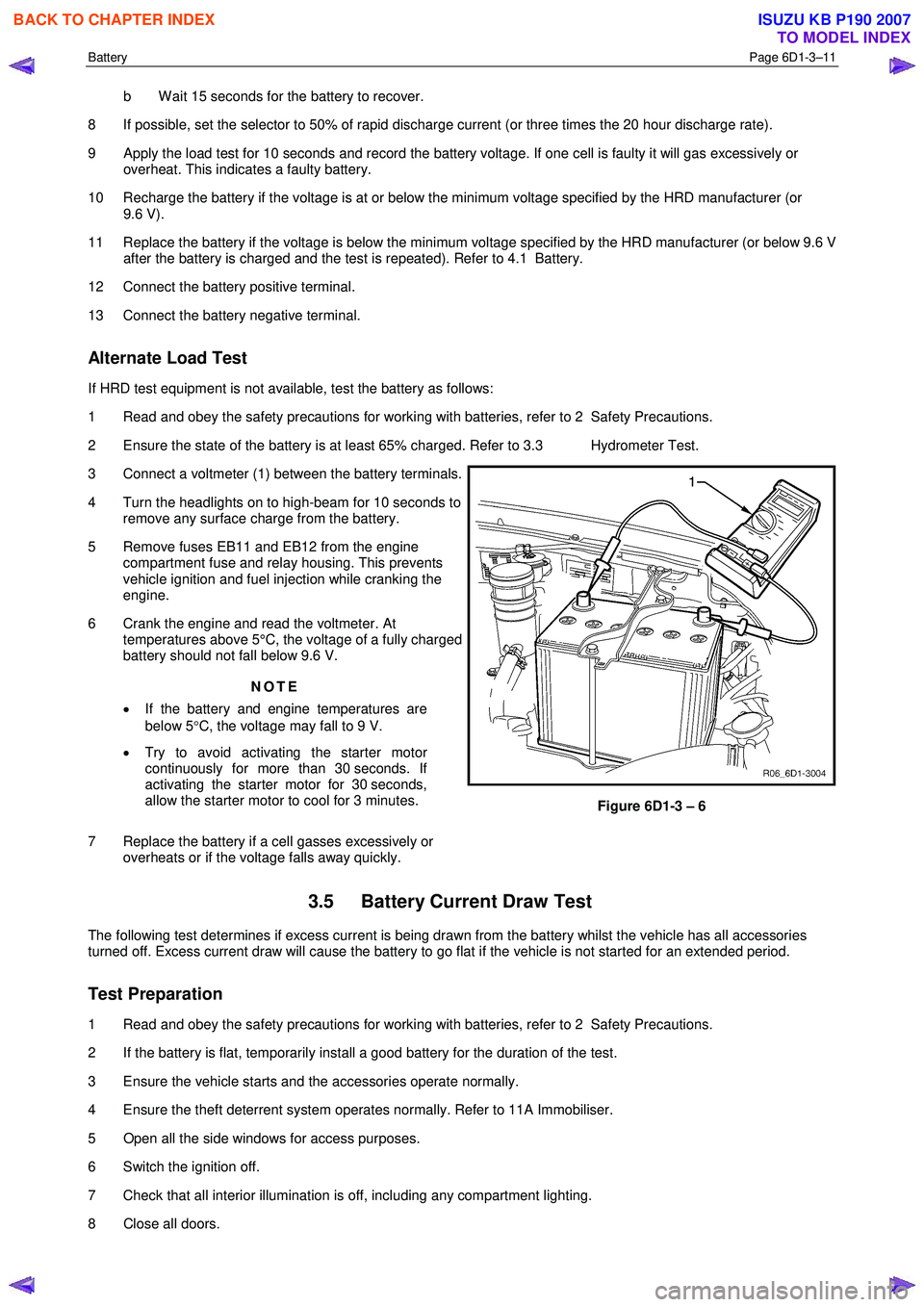
3 Connect a voltmeter (1) between the battery terminals.
4 Turn the headlights on to high-beam for 10 seconds to remove any surface charge from the battery.
5 Remove fuses EB11 and EB12 from the engine compartment fuse and relay housing. This prevents
vehicle ignition and fuel injection while cranking the
engine.
6 Crank the engine and read the voltmeter. At temperatures above 5°C, the voltage of a fully charged
battery should not fall below 9.6 V.
NOTE
• If the battery and engine temperatures are
below 5 °C, the voltage may fall to 9 V.
• Try to avoid activating the starter motor
continuously for more than 30 seconds. If
activating the starter motor for 30 seconds,
allow the starter motor to cool for 3 minutes.
7 Replace the battery if a cell gasses excessively or overheats or if the voltage falls away quickly.
Figure 6D1-3 – 6
3.5 Battery Current Draw Test
The following test determines if excess current is being drawn from the battery whilst the vehicle has all accessories
turned off. Excess current draw will cause the battery to go flat if the vehicle is not started for an extended period.
Test Preparation
1 Read and obey the safety precautions for working with batteries, refer to 2 Safety Precautions.
2 If the battery is flat, temporarily install a good battery for the duration of the test.
3 Ensure the vehicle starts and the accessories operate normally.
4 Ensure the theft deterrent system operates normally. Refer to 11A Immobiliser.
5 Open all the side windows for access purposes.
6 Switch the ignition off.
7 Check that all interior illumination is off, including any compartment lighting.
8 Close all doors.
BACK TO CHAPTER INDEX
TO MODEL INDEX
ISUZU KB P190 2007
Page 3662 of 6020
Powertrain Interface Module – V6 Page 6E1–1
6E1
Powertrain Interface Module – V6
ATTENTION
Before performing any service operation or other procedure described in this Section, refer to 1.2 Warning
Caution and Notes for correct workshop practices with regard to safety and / or property damage.
1 General Information ............................................................................................................ ...................6
1.1 General Description ............................................................................................................ ................................... 6
Serial Data Communication .................................................................................................................................. 6
Serial Data Layout.................................................................................................................................................. 8
1.2 Warning Caution and Notes .................................................................................................................................. 8
Definition of WARNING, CAUTION and NOTE Statements ............................................................................. .... 8
2 Component Location............................................................................................................................10
2.1 Engine Compartment............................................................................................................. .............................. 10
2.2 Interior................................................................................................................................................................... 11
3 Component Description and Operation ............................................................................................ .12
3.1 Powertrain Interface Module ............................................................................................................................... 12
3.2 Powertrain Interface Module Gateway Components ................................................................................. ....... 13
Engine Control Module........................................................................................................................................ 13
Immobiliser Control Unit ..................................................................................................................................... 13
Automatic Transmission Control Module .......................................................................................... ................ 13
3.3 Powertrain Interface Module Direct Input Switches.............................................................................. ............ 14
Cruise Control Switch.......................................................................................................................................... 14
Power Mode Switch – Automatic Transmission..................................................................................... ........... 14
3rd Start Switch – Automatic Transmission ....................................................................................................... 14
4 Diagnostics ...........................................................................................................................................15
4.1 Diagnostic General Descriptions................................................................................................ ........................ 15
Diagnostic Trouble Code (DTC) Tables........................................................................................... ................... 15
Diagnostic Trouble Codes (DTCs) ...................................................................................................................... 15
Tech 2 PIM Diagnostic Tests............................................................................................................................... 16
5 GM LAN Serial Communication Circuit ............................................................................................ ..17
6 Wiring Diagram and Connector Chart ................................................................................................18
6.1 Wiring Diagrams .................................................................................................................................................. 18
6.2 Connector Chart................................................................................................................................................... 20
6.3 Connector Information .......................................................................................................... .............................. 21
PIM Connector Pin Specifications ............................................................................................... ....................... 21
7 Diagnostics Starting Point ..................................................................................................................24
7.1 Diagnostic Requirements, Precautions and Preliminary Checks .................................................................... 24
Basic Knowledge Required ................................................................................................................................. 24
Basic Diagnostic Tools Required ................................................................................................ ....................... 24
Diagnostic Precautions ....................................................................................................................................... 24
Preliminary Checks.............................................................................................................................................. 25
7.2 Diagnostic System Check ........................................................................................................ ........................... 25
7.3 Powertrain Interface Module – Module Communication Check Failure Diagnostic Table............................. 27
BACK TO CHAPTER INDEX
TO MODEL INDEX
ISUZU KB P190 2007
Page 3664 of 6020
Powertrain Interface Module – V6 Page 6E1–3
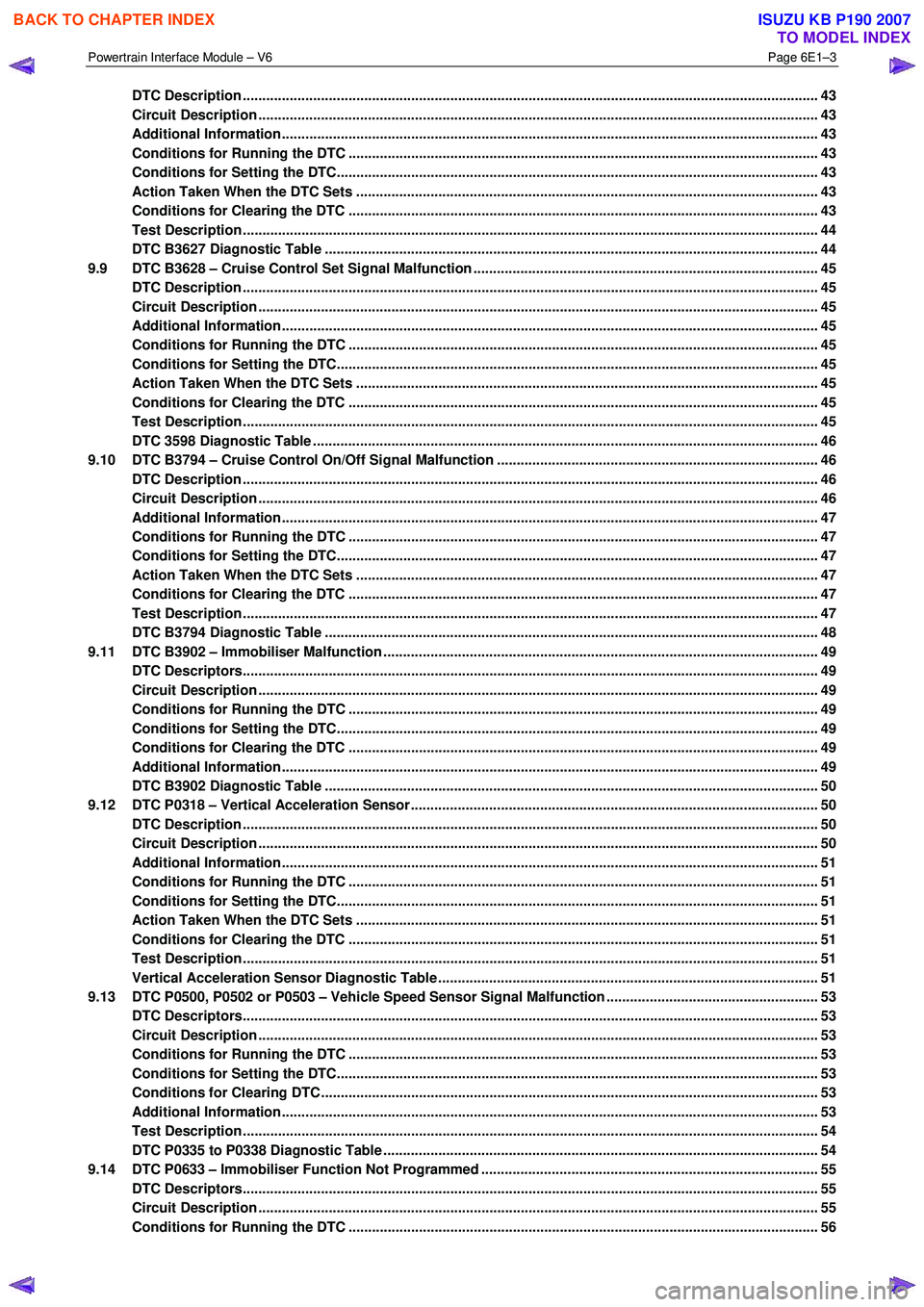
DTC Description ................................................................................................................................................... 43
Circuit Description ............................................................................................................................................... 43
Additional Information......................................................................................................... ................................ 43
Conditions for Running the DTC ................................................................................................. ....................... 43
Conditions for Setting the DTC........................................................................................................................... 43
Action Taken When the DTC Sets ................................................................................................. ..................... 43
Conditions for Clearing the DTC ........................................................................................................................ 43
Test Description ................................................................................................................................................... 44
DTC B3627 Diagnostic Table ..................................................................................................... ......................... 44
9.9 DTC B3628 – Cruise Control Set Signal Malfunction .............................................................................. .......... 45
DTC Description ................................................................................................................................................... 45
Circuit Description ............................................................................................................................................... 45
Additional Information......................................................................................................... ................................ 45
Conditions for Running the DTC ................................................................................................. ....................... 45
Conditions for Setting the DTC........................................................................................................................... 45
Action Taken When the DTC Sets ................................................................................................. ..................... 45
Conditions for Clearing the DTC ........................................................................................................................ 45
Test Description ................................................................................................................................................... 45
DTC 3598 Diagnostic Table ...................................................................................................... ........................... 46
9.10 DTC B3794 – Cruise Control On/Off Signal Malfunction ........................................................................... ....... 46
DTC Description ................................................................................................................................................... 46
Circuit Description ............................................................................................................................................... 46
Additional Information......................................................................................................... ................................ 47
Conditions for Running the DTC ................................................................................................. ....................... 47
Conditions for Setting the DTC........................................................................................................................... 47
Action Taken When the DTC Sets ................................................................................................. ..................... 47
Conditions for Clearing the DTC ........................................................................................................................ 47
Test Description ................................................................................................................................................... 47
DTC B3794 Diagnostic Table ..................................................................................................... ......................... 48
9.11 DTC B3902 – Immobiliser Malfunction ............................................................................................ ................... 49
DTC Descriptors................................................................................................................................................... 49
Circuit Description ............................................................................................................................................... 49
Conditions for Running the DTC ................................................................................................. ....................... 49
Conditions for Setting the DTC........................................................................................................................... 49
Conditions for Clearing the DTC ................................................................................................ ........................ 49
Additional Information......................................................................................................................................... 49
DTC B3902 Diagnostic Table ..................................................................................................... ......................... 50
9.12 DTC P0318 – Vertical Acceleration Sensor....................................................................................... ................. 50
DTC Description ................................................................................................................................................... 50
Circuit Description ............................................................................................................................................... 50
Additional Information......................................................................................................... ................................ 51
Conditions for Running the DTC ................................................................................................. ....................... 51
Conditions for Setting the DTC........................................................................................................................... 51
Action Taken When the DTC Sets ................................................................................................. ..................... 51
Conditions for Clearing the DTC ........................................................................................................................ 51
Test Description ................................................................................................................................................... 51
Vertical Acceleration Sensor Diagnostic Table .................................................................................. ............... 51
9.13 DTC P0500, P0502 or P0503 – Vehicle Speed Sensor Signal Malfunction ...................................................... 53
DTC Descriptors................................................................................................................................................... 53
Circuit Description ............................................................................................................................................... 53
Conditions for Running the DTC ................................................................................................. ....................... 53
Conditions for Setting the DTC........................................................................................................................... 53
Conditions for Clearing DTC ............................................................................................................................... 53
Additional Information......................................................................................................................................... 53
Test Description ................................................................................................................................................... 54
DTC P0335 to P0338 Diagnostic Table ............................................................................................ ................... 54
9.14 DTC P0633 – Immobiliser Function Not Programmed ................................................................................ ...... 55
DTC Descriptors................................................................................................................................................... 55
Circuit Description ............................................................................................................................................... 55
Conditions for Running the DTC ................................................................................................. ....................... 56
BACK TO CHAPTER INDEX
TO MODEL INDEX
ISUZU KB P190 2007
Page 3666 of 6020
Powertrain Interface Module – V6 Page 6E1–5
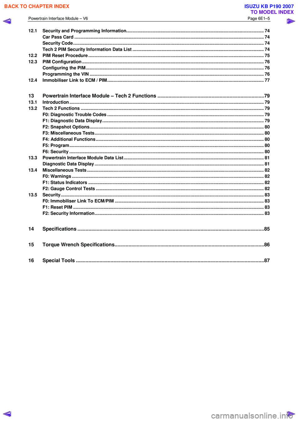
12.1 Security and Programming Information............................................................................................................. 74
Car Pass Card ...................................................................................................................................................... 74
Security Code ....................................................................................................................................................... 74
Tech 2 PIM Security Information Data List ...................................................................................... .................. 74
12.2 PIM Reset Procedure ........................................................................................................................................... 75
12.3 PIM Configuration ................................................................................................................................................ 76
Configuring the PIM ............................................................................................................ ................................. 76
Programming the VIN ............................................................................................................ .............................. 76
12.4 Immobiliser Link to ECM / PIM .................................................................................................. .......................... 77
13 Powertrain Interface Module – Tech 2 Functions .............................................................................79
13.1 Introduction .......................................................................................................................................................... 79
13.2 Tech 2 Functions ............................................................................................................... .................................. 79
F0: Diagnostic Trouble Codes ................................................................................................... ......................... 79
F1: Diagnostic Data Display................................................................................................................................ 79
F2: Snapshot Options.......................................................................................................................................... 80
F3: Miscellaneous Tests........................................................................................................ .............................. 80
F4: Additional Functions ..................................................................................................................................... 80
F5: Program .......................................................................................................................................................... 80
F6: Security .......................................................................................................................................................... 80
13.3 Powertrain Interface Module Data List .......................................................................................... ..................... 81
Diagnostic Data Display ...................................................................................................................................... 81
13.4 Miscellaneous Tests ............................................................................................................................................ 82
F0: Warnings ........................................................................................................................................................ 82
F1: Status Indicators .......................................................................................................... ................................. 82
F2: Gauge Control Tests ........................................................................................................ ............................. 82
13.5 Security................................................................................................................................................................. 83
F0: Immobiliser Link To ECM/PIM ................................................................................................ ...................... 83
F1: Reset PIM ....................................................................................................................................................... 83
F2: Security Information ....................................................................................................... ............................... 83
14 Specifications .......................................................................................................................................85
15 Torque Wrench Specifications................................................................................................... .........86
16 Special Tools ........................................................................................................................................87
BACK TO CHAPTER INDEX
TO MODEL INDEX
ISUZU KB P190 2007
Page 3667 of 6020
Powertrain Interface Module – V6 Page 6E1–6
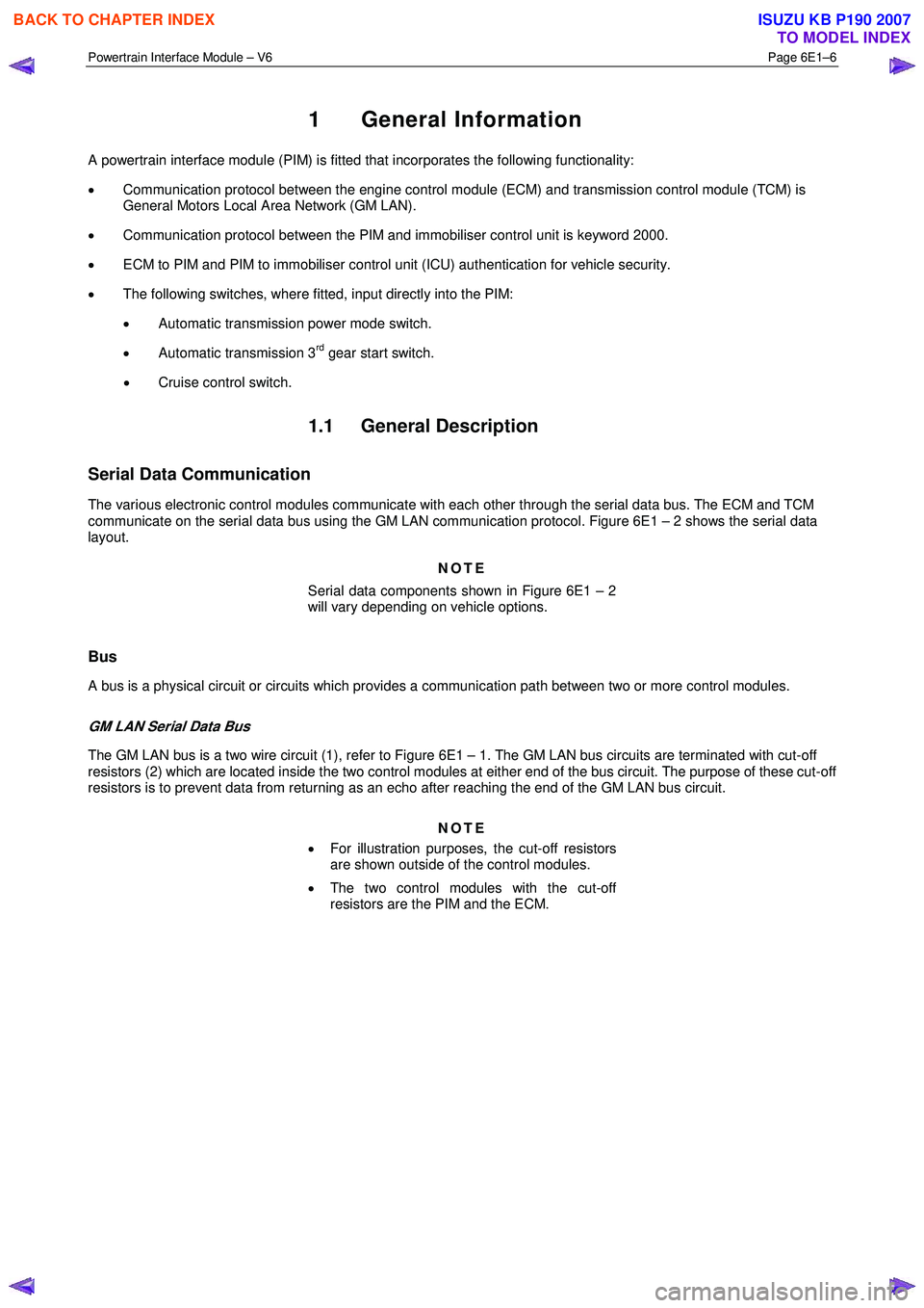
1 General Information
A powertrain interface module (PIM) is fitted that incorporates the following functionality:
• Communication protocol between the engine control module (ECM) and transmission control module (TCM) is
General Motors Local Area Network (GM LAN).
• Communication protocol between the PIM and immobiliser control unit is keyword 2000.
• ECM to PIM and PIM to immobiliser control unit (ICU) authentication for vehicle security.
• The following switches, where fitted, input directly into the PIM:
• Automatic transmission power mode switch.
• Automatic transmission 3
rd gear start switch.
• Cruise control switch.
1.1 General Description
Serial Data Communication
The various electronic control modules communicate with each other through the serial data bus. The ECM and TCM
communicate on the serial data bus using the GM LAN communication protocol. Figure 6E1 – 2 shows the serial data
layout.
NOTE
Serial data components shown in Figure 6E1 – 2
will vary depending on vehicle options.
Bus
A bus is a physical circuit or circuits which provides a communication path between two or more control modules.
GM LAN Serial Data Bus
The GM LAN bus is a two wire circuit (1), refer to Figure 6E1 – 1. The GM LAN bus circuits are terminated with cut-off
resistors (2) which are located inside the two control modules at either end of the bus circuit. The purpose of these cut-off
resistors is to prevent data from returning as an echo after reaching the end of the GM LAN bus circuit.
NOTE
• For illustration purposes, the cut-off resistors
are shown outside of the control modules.
• The two control modules with the cut-off
resistors are the PIM and the ECM.
BACK TO CHAPTER INDEX
TO MODEL INDEX
ISUZU KB P190 2007
Page 3669 of 6020
Powertrain Interface Module – V6 Page 6E1–8
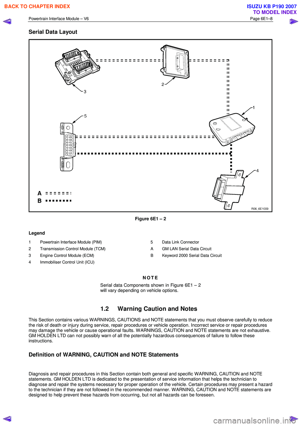
Serial Data Layout
Figure 6E1 – 2
Legend
1 Powertrain Interface Module (PIM)
2 Transmission Control Module (TCM)
3 Engine Control Module (ECM)
4 Immobiliser Control Unit (ICU)
5 Data Link Connector
A GM LAN Serial Data Circuit
B Keyword 2000 Serial Data Circuit
NOTE
Serial data Components shown in Figure 6E1 – 2
will vary depending on vehicle options.
1.2 Warning Caution and Notes
This Section contains various W ARNINGS, CAUTIONS and NOTE statements that you must observe carefully to reduce
the risk of death or injury during service, repair procedures or vehicle operation. Incorrect service or repair procedures
may damage the vehicle or cause operational faults. W ARNINGS, CAUTION and NOTE statements are not exhaustive.
GM HOLDEN LTD can not possibly warn of all the potentially hazardous consequences of failure to follow these
instructions.
Definition of WARNING, CAUTION and NOTE Statements
Diagnosis and repair procedures in this Section contain both general and specific W ARNING, CAUTION and NOTE
statements. GM HOLDEN LTD is dedicated to the presentation of service information that helps the technician to
diagnose and repair the systems necessary for proper operation of the vehicle. Certain procedures may present a hazard
to the technician if they are not followed in the recommended manner. W ARNING, CAUTION and NOTE statements are
designed to help prevent these hazards from occurring, but not all hazards can be foreseen.
BACK TO CHAPTER INDEX
TO MODEL INDEX
ISUZU KB P190 2007