2007 ISUZU KB P190 catalytic converter
[x] Cancel search: catalytic converterPage 3521 of 6020
Engine Management – V6 – Diagnostics Page 6C1-2–243
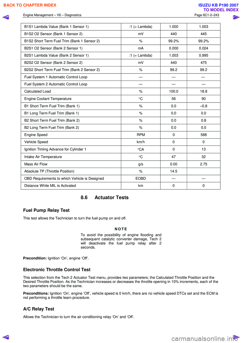
B1S1 Lambda Value (Bank 1 Sensor 1) :1 (= Lambda) 1.000 1.003
B1S2 O2 Sensor (Bank 1 Sensor 2) mV 440 445
B1S2 Short Term Fuel Trim (Bank 1 Sensor 2) % 99.2% 99.2%
B2S1 O2 Sensor (Bank 2 Sensor 1) mA 0.000 0.024
B2S1 Lambda Value (Bank 2 Sensor 1) :1 (= Lambda) 1.003 0.995
B2S2 O2 Sensor (Bank 2 Sensor 2) mV 440 475
B2S2 Short Term Fuel Trim (Bank 2 Sensor 2) % 99.2 99.2
Fuel System 1 Automatic Control Loop — — —
Fuel System 2 Automatic Control Loop — — —
Calculated Load % 100.0 18.8
Engine Coolant Temperature
°C 56 90
B1 Short Term Fuel Trim (Bank 1)
% 0.0 –0.8
B1 Long Term Fuel Trim (Bank 1) % 0.0 0.0
B2 Short Term Fuel Trim (Bank 2) % 0.0 0.8
B2 Long Term Fuel Trim (Bank 2) % 0.0 0.0
Engine Speed RPM 0 588
Vehicle Speed km/h 0 0
Ignition Timing Advance for Cylinder 1
°CA 0 13
Intake Air Temperature
°C 47 32
Mass Air Flow
g/s 0.00 2.75
Absolute TP (Throttle Position) % 14.5
OBD Requirements to which Vehicle is Designed EOBD — —
Distance W hile MIL is Activated km 0 0
8.6 Actuator Tests
Fuel Pump Relay Test
This test allows the Technician to turn the fuel pump on and off.
NOTE
To avoid the possibility of engine flooding and
subsequent catalytic converter damage, Tech 2
will deactivate the fuel pump relay after 2
seconds.
Precondition: Ignition ‘On’, engine ‘Off’.
Electronic Throttle Control Test
This selection from the Tech 2 Actuator Test menu, provides two parameters; the Calculated Throttle Position and the
Desired Throttle Position. As the Technician increases or decreases the throttle opening in 10% increments, each of the
two parameters should be the same.
Preconditions: Ignition ‘On’, engine ‘Off’, vehicle speed is 0 km/h, there are no vehicle speed DTCs set and the ECM is
not performing a throttle learn procedure.
A/C Relay Test
Allows the Technician to turn the air conditioning relay ‘On’ and ‘Off’.
BACK TO CHAPTER INDEX
TO MODEL INDEX
ISUZU KB P190 2007
Page 3566 of 6020
Engine Management – V6 – Service Operations Page 6C1-3–42
4 Observe the resistance values as the temperature
increases and compare the temperature / resistance
change to the specifications.
5 If the resistance is not within specifications, replace the MAF sensor.
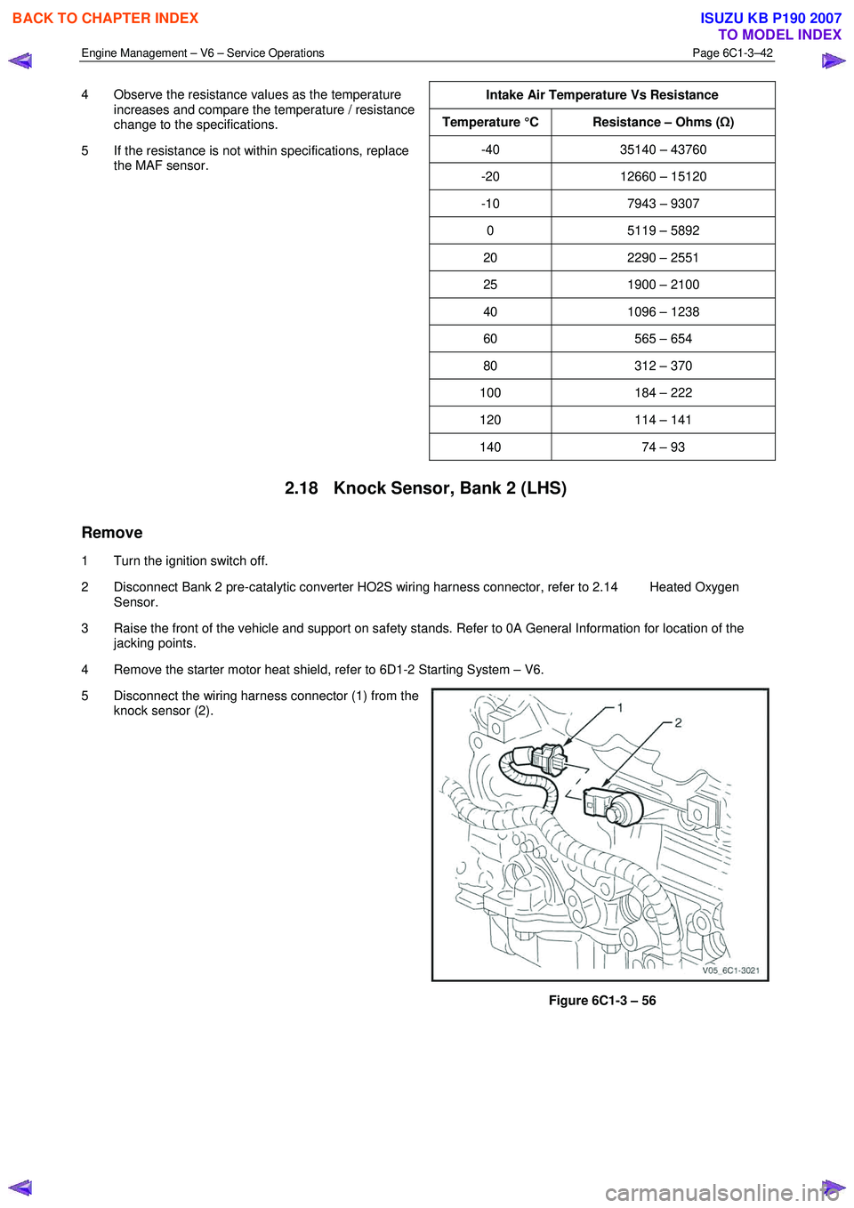
Intake Air Temperature Vs Resistance
Temperature °C Resistance – Ohms (
Ω)
-40 35140 – 43760
-20 12660 – 15120
-10 7943 – 9307
0 5119 – 5892
20 2290 – 2551
25 1900 – 2100
40 1096 – 1238
60 565 – 654
80 312 – 370
100 184 – 222
120 114 – 141
140 74 – 93
2.18 Knock Sensor, Bank 2 (LHS)
Remove
1 Turn the ignition switch off.
2 Disconnect Bank 2 pre-catalytic converter HO2S wiring harness connector, refer to 2.14 Heated Oxygen Sensor.
3 Raise the front of the vehicle and support on safety stands. Refer to 0A General Information for location of the jacking points.
4 Remove the starter motor heat shield, refer to 6D1-2 Starting System – V6.
5 Disconnect the wiring harness connector (1) from the knock sensor (2).
Figure 6C1-3 – 56
BACK TO CHAPTER INDEX
TO MODEL INDEX
ISUZU KB P190 2007
Page 3656 of 6020
Battery Page 6D1-3–16
NOTE
Charging a battery at higher current rates can
significantly reduce the life of the battery.
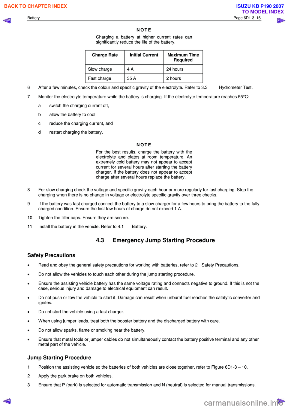
Charge Rate Initial Current Maximum Time Required
Slow charge 4 A 24 hours
Fast charge 35 A 2 hours
6 After a few minutes, check the colour and specific gravity of the electrolyte. Refer to 3.3 Hydrometer Test.
7 Monitor the electrolyte temperature while the battery is charging. If the electrolyte temperature reaches 55 °C:
a switch the charging current off,
b allow the battery to cool,
c reduce the charging current, and
d restart charging the battery.
NOTE
For the best results, charge the battery with the
electrolyte and plates at room temperature. An
extremely cold battery may not appear to accept
current for several hours after starting the battery
charger. If the battery does not appear to accept
charge after several hours replace the battery.
8 For slow charging check the voltage and specific gravity each hour or more regularly for fast charging. Stop the charging when there is no change in voltage or electrolyte specific gravity over three checks.
9 If the battery was fast charged connect the battery to a slow-charger for a few hours to bring the battery to the fully charged condition. Ensure the last few hours of charge do not exceed 1 A.
10 Tighten the filler caps. Ensure they are secure.
11 Install the battery in the vehicle. Refer to 4.1 Battery.
4.3 Emergency Jump Starting Procedure
Safety Precautions
• Read and obey the general safety precautions for working with batteries, refer to 2 Safety Precautions.
• Do not allow the vehicles to touch each other during the jump starting procedure.
• Ensure the assisting vehicle battery has the same voltage rating and connects negative to ground. If this is not the
case, serious injury and damage to electrical equipment can result.
• Do not push or tow the vehicle to start it. Damage can result when unburnt fuel reaches the catalytic converter and
ignites.
• Do not start the vehicle using a fast charger.
• W hen using jumper leads, treat both the booster battery and the discharged battery with care.
• Do not allow sparks, flame or smoking near the battery.
• Ensure that metal tools or jumper cables do not simultaneously contact the battery positive terminal and any other
metal part of the vehicle.
Jump Starting Procedure
1 Position the assisting vehicle so the batteries of both vehicles are close together, refer to Figure 6D1-3 – 10.
2 Apply the park brake on both vehicles.
3 Ensure that P (park) is selected for automatic transmission and N (neutral) is selected for manual transmissions.
BACK TO CHAPTER INDEX
TO MODEL INDEX
ISUZU KB P190 2007
Page 3750 of 6020
Exhaust System – V6 Page 6F – 2
1 General Information
Information contained within this section describes the general exhaust system.
1.1 Emission Reductions
Through developments in various vehicle emissions reduction systems, significant reductions in emissions have been
achieved. The developments have been primarily concerned with refinements in engine calibration and the optimisation
of exhaust system catalytic converter configurations.
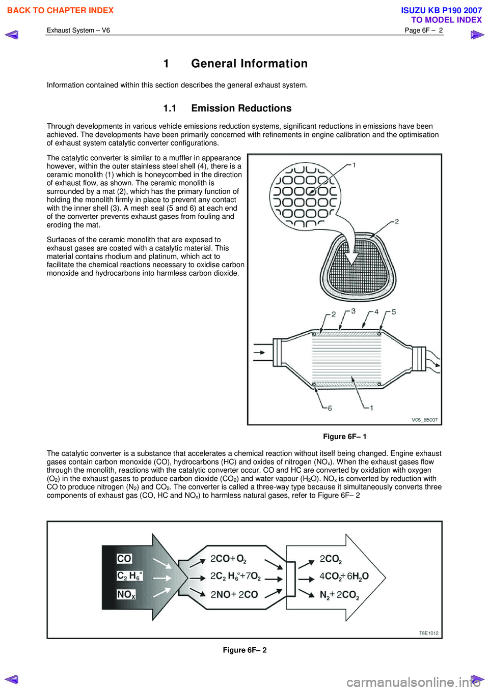
The catalytic converter is similar to a muffler in appearance
however, within the outer stainless steel shell (4), there is a
ceramic monolith (1) which is honeycombed in the direction
of exhaust flow, as shown. The ceramic monolith is
surrounded by a mat (2), which has the primary function of
holding the monolith firmly in place to prevent any contact
with the inner shell (3). A mesh seal (5 and 6) at each end
of the converter prevents exhaust gases from fouling and
eroding the mat.
Surfaces of the ceramic monolith that are exposed to
exhaust gases are coated with a catalytic material. This
material contains rhodium and platinum, which act to
facilitate the chemical reactions necessary to oxidise carbon
monoxide and hydrocarbons into harmless carbon dioxide.
Figure 6F– 1
The catalytic converter is a substance that accelerates a chemical reaction without itself being changed. Engine exhaust
gases contain carbon monoxide (CO), hydrocarbons (HC) and oxides of nitrogen (NO
x). W hen the exhaust gases flow
through the monolith, reactions with the catalytic converter occur. CO and HC are converted by oxidation with oxygen
(O
2) in the exhaust gases to produce carbon dioxide (CO2) and water vapour (H2O). NOx is converted by reduction with
CO to produce nitrogen (N
2) and CO2. The converter is called a three-way type because it simultaneously converts three
components of exhaust gas (CO, HC and NO
x) to harmless natural gases, refer to Figure 6F– 2
Figure 6F– 2
BACK TO CHAPTER INDEX
TO MODEL INDEX
ISUZU KB P190 2007
Page 3751 of 6020
Exhaust System – V6 Page 6F – 3
The Catalytic converter can be damaged or
rendered ineffective, if:
• operated outside the limits of the closed
loop mixture control system
• the engine burns excessive amount of oil
• the exhaust temperature at the converter
is too high (exceeds 840°C).
The catalytic material is very sensitive to the effects of a rich or lean fuel mixture, which may cause the temperature of
the converter to rise rapidly. The catalytic converter normally operates at approximately 600 °C.
The catalytic converter is also sensitive to the use of leaded petrol. Using leaded fuel can cause deposits to form in the
converter, which restrict exhaust flow and prevent the catalyst from working. This will result in an increase in exhaust
backpressure and converter temperature.
NOTE
The use of unleaded petrol results in black
tailpipe deposits rather than the grey colour that
some people may normally associate with an
acceptable combustion condition. This black
colour resulting from the use of unleaded fuel
does not necessarily indicate a state of poor
engine tune. For V6 engines, Refer to: 6C1 – 1
Engine Management General Information.
Euro 3 Emissions Standards
The Euro 3 emissions standard is a European standard which aims at setting vehicle emissions targets to encourage
vehicle manufacturers to reduce harmful vehicle emissions such as Carbon Monoxide (CO), Hydrocarbons (HC) and the
various oxides of Nitrogen (NOx).
This vehicle is fitted with a supplemental
restraint system (SRS). Refer to section 9A
Restraints, in order to determine whether you
are performing service on or near the SRS
components or the SRS wiring.
Always use the correct fastener in the proper
location. When you replace a fastener, use
ONLY the exact part number for that
application. Isuzu will identify those fasteners
that require a replacement after removal and
fasteners that require thread lockers or thread
sealant. Unless otherwise specified, do not
use supplemental coatings (Paints, greases
or corrosion inhibitors) on thread fasteners or
fastener joints. Generally such coatings
adversely effect the fastener torque and the
joint clamping force, and may damage the
fastener. When you install fasteners, use the
correct tightening sequence and torque
specifications.
BACK TO CHAPTER INDEX
TO MODEL INDEX
ISUZU KB P190 2007
Page 3752 of 6020
Exhaust System – V6 Page 6F – 4
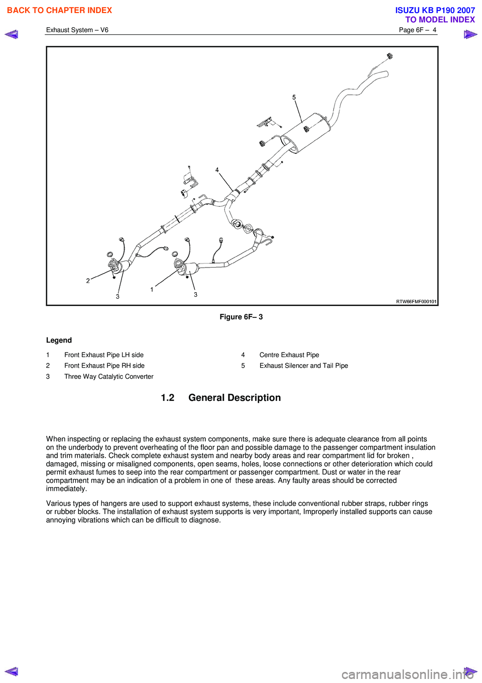
Figure 6F– 3
Legend
1 Front Exhaust Pipe LH side
2 Front Exhaust Pipe RH side
3 Three Way Catalytic Converter 4 Centre Exhaust Pipe
5 Exhaust Silencer and Tail Pipe
1.2 General Description
W hen inspecting or replacing the exhaust system components, make sure there is adequate clearance from all points
on the underbody to prevent overheating of the floor pan and possible damage to the passenger compartment insulation
and trim materials. Check complete exhaust system and nearby body areas and rear compartment lid for broken ,
damaged, missing or misaligned components, open seams, holes, loose connections or other deterioration which could
permit exhaust fumes to seep into the rear compartment or passenger compartment. Dust or water in the rear
compartment may be an indication of a problem in one of these areas. Any faulty areas should be corrected
immediately.
Various types of hangers are used to support exhaust systems, these include conventional rubber straps, rubber rings
or rubber blocks. The installation of exhaust system supports is very important, Improperly installed supports can cause
annoying vibrations which can be difficult to diagnose.
BACK TO CHAPTER INDEX
TO MODEL INDEX
ISUZU KB P190 2007
Page 3753 of 6020
Exhaust System – V6 Page 6F – 5
Service Notes
1. Vehicles fitted with catalytic converters should not be operated with leaded petrol. Lead will contaminate
the ceramic monolith.
2. Do not drop the catalytic converter as it will damage the ceramic monolith.
3. Replace the catalytic converter if it is damaged.
4. Do not allow water, oil or fuel to enter the converter as the ceramic monolith will be contaminated.
5. Do not use engine and/or fuel additives unless approved by General Motors. Many additives contain phosphorous that will contaminate the ceramic monolith.
6. The vehicle must not be started by pushing or towing, as unburned fuel could reach the catalytic converter and destroy the ceramic monolith. Always use jumper leads to start a vehicle that has a flat or
defective battery.
7. W hen carrying out a compression test, for V6 engines use Tech 2 to ensure the output control Engine Compression Test is set to enable, refer to 6A1 Engine Mechanical. This prevents fuel injection and
ignition during engine cranking.
8. Do not drive the vehicle with the engine misfiring or with any of the spark plug leads disconnected, as the catalytic converter will overheat.
9. Do not coast downhill with the engine misfiring or with any of the spark plug leads disconnected.
10. The catalytic converter is serviceable as part of the front exhaust assembly only. Refer to the service operations in this section for details of front exhaust pipe assembly removal and reinstallation.
11. The exhaust flange gaskets must be replaced whenever a new exhaust pipe, muffler or catalytic converter is installed.
1.3 WARNING, CAUTION and NOTES
This Section contains various W ARNINGS, CAUTIONS and NOTE statements that you must observe carefully to reduce
the risk of death or injury during service, repair procedures or vehicle operation. Incorrect service or repair procedures
may damage the vehicle or cause operational faults. W ARNINGS, CAUTION and NOTE statements are not exhaustive.
HOLDEN LTD can not possibly warn of all the potentially hazardous consequences of failure to follow these instructions.
1.1 Definition of WARNING, CAUTION and NOTE Statements
Diagnosis and repair procedures in this Section contain both general and specific W ARNING, CAUTION and NOTE
statements. HOLDEN LTD is dedicated to the presentation of service information that helps the technician to diagnose
and repair the systems necessary for proper operation of the vehicle. Certain procedures may present a hazard to the
technician if they are not followed in the recommended manner. W ARNING, CAUTION and NOTE statements are
designed to help prevent these hazards from occurring, but not all hazards can be foreseen.
WARNING defined
A W ARNING statement immediately precedes an operating procedure or maintenance practice which, if not correctly
followed, could result in death or injury. A W ARNING statement alerts you to take necessary action or not to take a
prohibited action. If a W ARNING statement is ignored, the following consequences may occur:
• Death or injury to the technician or other personnel working on the vehicle,
• Death or injury to other people in or near the workplace area, and / or
• Death or injury to the driver / or passenger(s) of the vehicle or other people, if the vehicle has been improperly
repaired.
CAUTION defined
A CAUTION statement immediately precedes an operating procedure or maintenance practice which, if not correctly
followed, could result in damage to or destruction of equipment, or corruption of data. If a CAUTION statement is
ignored, the following consequences may occur:
• Damage to the vehicle,
• Unnecessary vehicle repairs or component replacement,
BACK TO CHAPTER INDEX
TO MODEL INDEX
ISUZU KB P190 2007
Page 3755 of 6020
Exhaust System – V6 Page 6F – 7
2 Front and Centre Exhaust Pipe
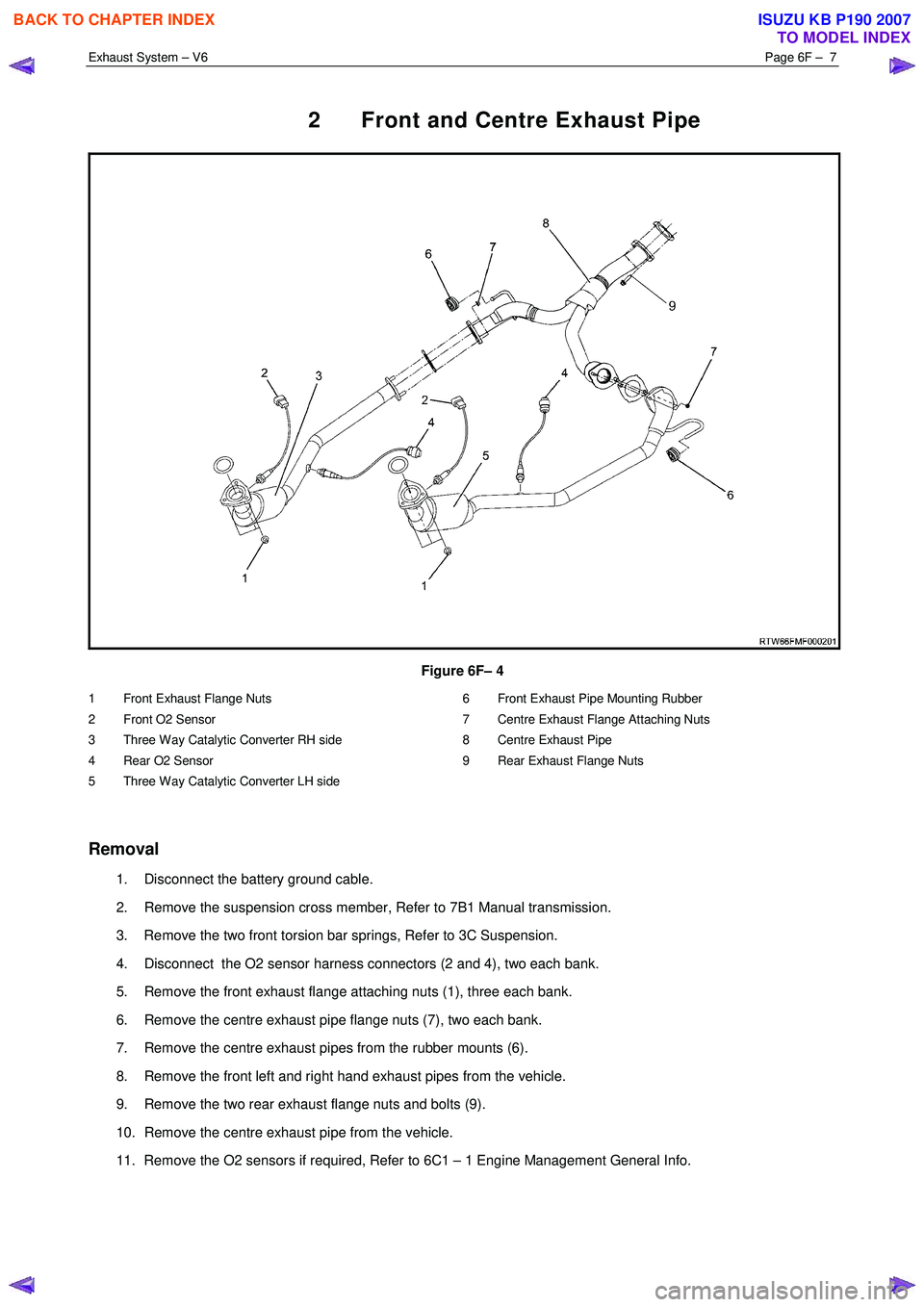
Figure 6F– 4
1 Front Exhaust Flange Nuts
2 Front O2 Sensor
3 Three Way Catalytic Converter RH side
4 Rear O2 Sensor
5 Three Way Catalytic Converter LH side 6 Front Exhaust Pipe Mounting Rubber
7 Centre Exhaust Flange Attaching Nuts
8 Centre Exhaust Pipe
9 Rear Exhaust Flange Nuts
Removal
1. Disconnect the battery ground cable.
2. Remove the suspension cross member, Refer to 7B1 Manual transmission.
3. Remove the two front torsion bar springs, Refer to 3C Suspension.
4. Disconnect the O2 sensor harness connectors (2 and 4), two each bank.
5. Remove the front exhaust flange attaching nuts (1), three each bank.
6. Remove the centre exhaust pipe flange nuts (7), two each bank.
7. Remove the centre exhaust pipes from the rubber mounts (6).
8. Remove the front left and right hand exhaust pipes from the vehicle.
9. Remove the two rear exhaust flange nuts and bolts (9).
10. Remove the centre exhaust pipe from the vehicle.
11. Remove the O2 sensors if required, Refer to 6C1 – 1 Engine Management General Info.
BACK TO CHAPTER INDEX
TO MODEL INDEX
ISUZU KB P190 2007